service LAND ROVER FREELANDER 2001 User Guide
[x] Cancel search | Manufacturer: LAND ROVER, Model Year: 2001, Model line: FREELANDER, Model: LAND ROVER FREELANDER 2001Pages: 1007, PDF Size: 23.47 MB
Page 45 of 1007
GENERAL INFORMATION
03-14
Self-locking nuts
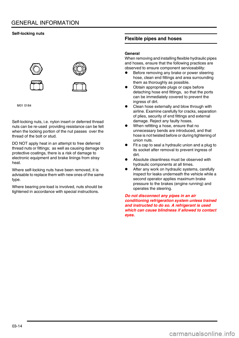
Self-locking nuts, i.e. nylon insert or deferred thread
nuts can be re-used providing resistance can be felt
when the locking portion of the nut passes over the
thread of the bolt or stud.
DO NOT apply heat in an attempt to free deferred
thread nuts or fittings; as well as causing damage to
protective coatings, there is a risk of damage to
electronic equipment and brake linings from stray
heat.
Where self-locking nuts have been removed, it is
advisable to replace them with new ones of the same
type.
Where bearing pre-load is involved, nuts should be
tightened in accordance with special instructions.
Flexible pipes and hoses
General
When removing and installing flexible hydraulic pipes
and hoses, ensure that the following practices are
observed to ensure component serviceability:
lBefore removing any brake or power steering
hose, clean end fittings and area surrounding
them as thoroughly as possible.
lObtain appropriate plugs or caps before
detaching hose end fittings, so that the ports
can be immediately covered to prevent the
ingress of dirt.
lClean hose externally and blow through with
airline. Examine carefully for cracks, separation
of plies, security of end fittings and external
damage. Reject any faulty hoses.
lWhen refitting a hose, ensure that no
unnecessary bends are introduced, and that
hose is not twisted before or during tightening of
union nuts.
lFit a cap to seal a hydraulic union and a plug to
its socket after removal to prevent ingress of
dirt.
lAbsolute cleanliness must be observed with
hydraulic components at all times.
lAfter any work on hydraulic systems, carefully
inspect for leaks underneath the vehicle while a
second operator applies maximum brake
pressure to the brakes (engine running) and
operates the steering.
Do not disconnect any pipes in an air
conditioning refrigeration system unless trained
and instructed to do so. A refrigerant is used
which can cause blindness if allowed to contact
eyes.
Page 47 of 1007
GENERAL INFORMATION
03-16
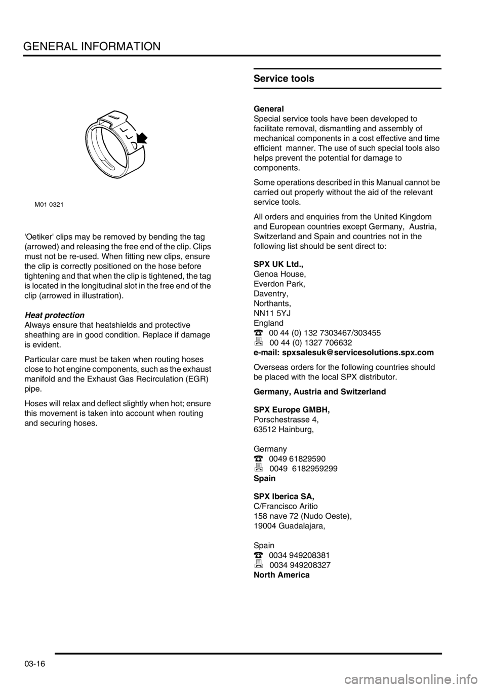
'Oetiker' clips may be removed by bending the tag
(arrowed) and releasing the free end of the clip. Clips
must not be re-used. When fitting new clips, ensure
the clip is correctly positioned on the hose before
tightening and that when the clip is tightened, the tag
is located in the longitudinal slot in the free end of the
clip (arrowed in illustration).
Heat protection
Always ensure that heatshields and protective
sheathing are in good condition. Replace if damage
is evident.
Particular care must be taken when routing hoses
close to hot engine components, such as the exhaust
manifold and the Exhaust Gas Recirculation (EGR)
pipe.
Hoses will relax and deflect slightly when hot; ensure
this movement is taken into account when routing
and securing hoses.
Service tools
General
Special service tools have been developed to
facilitate removal, dismantling and assembly of
mechanical components in a cost effective and time
efficient manner. The use of such special tools also
helps prevent the potential for damage to
components.
Some operations described in this Manual cannot be
carried out properly without the aid of the relevant
service tools.
All orders and enquiries from the United Kingdom
and European countries except Germany, Austria,
Switzerland and Spain and countries not in the
following list should be sent direct to:
SPX UK Ltd.,
Genoa House,
Everdon Park,
Daventry,
Northants,
NN11 5YJ
England
( 00 44 (0) 132 7303467/303455
) 00 44 (0) 1327 706632
e-mail: [email protected]
Overseas orders for the following countries should
be placed with the local SPX distributor.
Germany, Austria and Switzerland
SPX Europe GMBH,
Porschestrasse 4,
63512 Hainburg,
Germany
( 0049 61829590
) 0049 6182959299
Spain
SPX Iberica SA,
C/Francisco Aritio
158 nave 72 (Nudo Oeste),
19004 Guadalajara,
Spain
( 0034 949208381
) 0034 949208327
North America
Page 50 of 1007
GENERAL INFORMATION
03-19
Electrical precautions
General
The following guidelines are intended to ensure the
safety of the operator and ensure the prevention of
damage to the electrical and electronic components
fitted to the vehicle. Where necessary, specific
precautions are detailed in the individual procedures
of this manual.
Equipment
Prior to commencing any test procedure on the
vehicle, ensure that the relevant test equipment is
working correctly and any harness or connectors are
in good condition. It is particularly important to check
the condition of the lead and plugs of mains operated
equipment.
Polarity
Never reverse connect the vehicle battery and
always ensure the correct polarity when connecting
test equipment.
High Voltage Circuits
Whenever disconnecting live ht circuits, always use
insulated pliers and never allow the open end of the
ht lead to contact other components, particularly
ECU's.
Exercise caution when measuring the voltage on the
coil terminals while the engine is running, high
voltage spikes can occur on these terminals.
Connectors and harnesses
The engine compartment of a vehicle is a particularly
hostile environment for electrical components and
connectors:
lAlways ensure electrically related items are dry
and oil free before disconnecting and
connecting test equipment.
lEnsure disconnected multiplugs and sensors
are protected from being contaminated with oil,
coolant or other solutions. Contamination could
impair performance or result in catastrophic
failure.
lNever force connectors apart using tools to
prise apart or by pulling on the wiring harness.
lAlways ensure locking tabs are disengaged
before disconnection, and match orientation to
enable correct reconnection.
lEnsure that any protection (covers, insulation
etc.) is replaced if disturbed.Having confirmed a component to be faulty:
lSwitch off the ignition and disconnect the
battery.
lRemove the component and support the
disconnected harness.
lWhen replacing the component, keep oily hands
away from electrical connection areas and push
connectors home until any locking tabs fully
engage.
Battery disconnection
Before disconnecting the battery, disable the alarm
system and switch off all electrical equipment. If the
radio is to be serviced, ensure the security code has
been deactivated.
CAUTION: To prevent damage to electrical
components, always disconnect the battery
when working on the vehicle's electrical system.
The ground lead must be disconnected first and
reconnected last.
CAUTION: Always ensure that battery leads are
routed correctly and are not close to any
potential chafing points.
Battery charging
Only recharge the battery with it removed from the
vehicle. Always ensure any battery charging area is
well ventilated and that every precaution is taken to
avoid naked flames and sparks.
Ignition system safety precautions
The vehicle's ignition system produces high voltages
and the following precautions should be observed
before carrying out any work on the system:
WARNING: Before commencing work on an
ignition system, ensure all high tension
terminals, adapters and diagnostic equipment
are adequately insulated and shielded to prevent
accidental personal contacts and minimise the
risk of shock. Wearers of surgically implanted
pacemaker devices should not be in close
proximity of ignition circuits or diagnostic
equipment.
Page 51 of 1007
GENERAL INFORMATION
03-20
Disciplines
Switch off the ignition prior to making any connection
or disconnection in the system, to prevent electrical
surges caused by disconnecting 'live' connections
damaging electronic components.
Ensure hands and work surfaces are clean and free
of grease, swarf, etc. Grease collects dirt which can
cause electrical tracking (short-circuits) or high-
resistance contacts.
When handling printed circuit boards, treat with care
and hold by the edges only; note that some electronic
components are susceptible to body static.
Connectors should never be subjected to forced
removal or refit, especially inter-board connectors.
Damaged contacts can cause short-circuit and
open-circuit fault conditions.
Prior to commencing test, and periodically during a
test, touch a good vehicle body earth to discharge
static charge. Some electronic components are
vulnerable to the static electricity that may be
generated by the operator.
Grease for electrical connectors
Some under bonnet and under body connectors may
be protected against corrosion by the application of a
special grease during vehicle production. Should
connectors be disturbed in service, or repaired or
replaced, additional grease should be re-applied:
Part No. BAU 5811, available in 150 gm tubs.
NOTE: The use of greases other than BAU 5811
must be avoided as they can migrate into relays,
switches etc. contaminating the contacts and leading
to intermittent operation or failure.
Supplementary restraint system
precautions
General
The Supplementary Restraint System (SRS)
provides active protection for vehicle occupants in
the event of a serious collision. The system
components include airbags and pre-tensioner seat
belts which are automatically deployed when a
severe frontal crash condition is detected.
The SRS pyrotechnic components could be
potentially hazardous to the service engineer if not
handled correctly. The following guidelines are
intended to alert the service engineer to potential
sources of danger and emphasise the importance of
ensuring the integrity of SRS components fitted to
the vehicle.
In order to assure system integrity, it is essential that
the SRS system is regularly checked and maintained
so that it is ready for operation in the event of an
accident.
Where necessary, additional specific precautions are
detailed in the relevant sections of this Manual which
should be referred to prior to commencing repair
operations.
WARNING: Always follow the 'SRS Precautions'
and the correct procedures for working on SRS
components. Persons working on SRS systems
must be fully trained and have been issued with
copies of the Safety guidelines.
WARNING: It is imperative that before any work
is undertaken on the SRS system the appropriate
information is read thoroughly.
WARNING: The airbag module contains sodium
azide which is poisonous and extremely
flammable. Contact with water, acid or heavy
metals may produce harmful or explosive
compounds. Do not dismantle, incinerate or
bring into contact with electricity, before the unit
has been deployed.
WARNING: Always replace a seat belt assembly
that has withstood the strain of a severe vehicle
impact, or if the webbing shows signs of fraying.
WARNING: Always disconnect the vehicle
battery before carrying out any electric welding
on a vehicle fitted with an SRS system.
CAUTION: Do not expose an airbag module or
seat belt pre-tensioner to heat exceeding 85º C
(185º F).
Page 52 of 1007
GENERAL INFORMATION
03-21
It should be noted that these precautions are not
restricted to operations performed when servicing
the SRS system, the same care should be exercised
when working on ancillary systems and components
located in the vicinity of SRS components; these
include but are not limited to:
lSteering system – steering wheel airbag,
rotary coupler.
lFront fascia – passenger front airbag (where
fitted); SRS DCU behind centre console, on
transmission tunnel under the HeVAC system.
lFront seats – seat belt pre-tensioners, integral
with seat belt buckle assembly.
lElectrical system – SRS harnesses, link leads
and connectors.
Making the SRS system safe
Before working on or in the vicinity of SRS
components, ensure the system is rendered safe by
performing the following procedures:
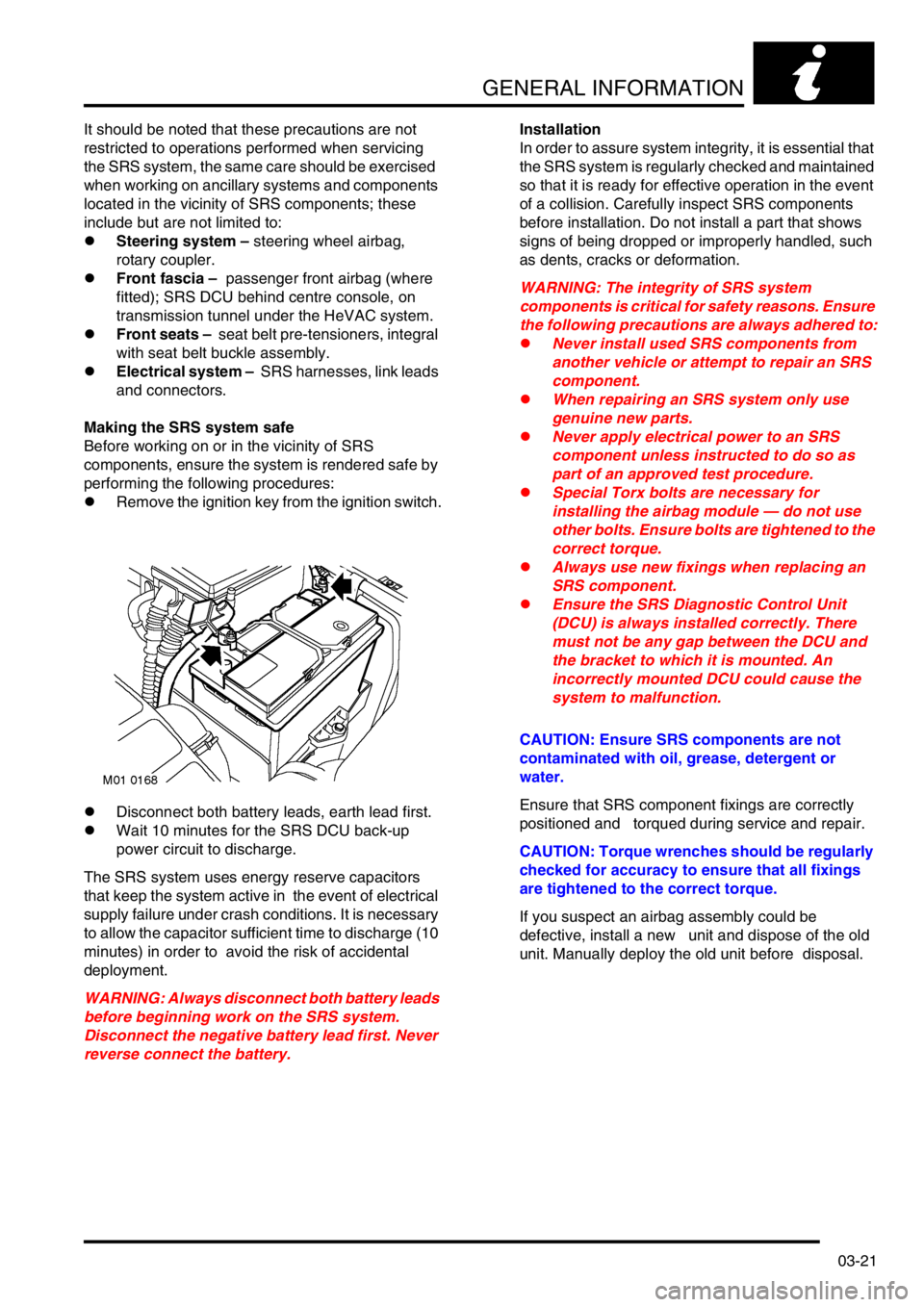
lRemove the ignition key from the ignition switch.
lDisconnect both battery leads, earth lead first.
lWait 10 minutes for the SRS DCU back-up
power circuit to discharge.
The SRS system uses energy reserve capacitors
that keep the system active in the event of electrical
supply failure under crash conditions. It is necessary
to allow the capacitor sufficient time to discharge (10
minutes) in order to avoid the risk of accidental
deployment.
WARNING: Always disconnect both battery leads
before beginning work on the SRS system.
Disconnect the negative battery lead first. Never
reverse connect the battery.Installation
In order to assure system integrity, it is essential that
the SRS system is regularly checked and maintained
so that it is ready for effective operation in the event
of a collision. Carefully inspect SRS components
before installation. Do not install a part that shows
signs of being dropped or improperly handled, such
as dents, cracks or deformation.
WARNING: The integrity of SRS system
components is critical for safety reasons. Ensure
the following precautions are always adhered to:
lNever install used SRS components from
another vehicle or attempt to repair an SRS
component.
lWhen repairing an SRS system only use
genuine new parts.
lNever apply electrical power to an SRS
component unless instructed to do so as
part of an approved test procedure.
lSpecial Torx bolts are necessary for
installing the airbag module — do not use
other bolts. Ensure bolts are tightened to the
correct torque.
lAlways use new fixings when replacing an
SRS component.
lEnsure the SRS Diagnostic Control Unit
(DCU) is always installed correctly. There
must not be any gap between the DCU and
the bracket to which it is mounted. An
incorrectly mounted DCU could cause the
system to malfunction.
CAUTION: Ensure SRS components are not
contaminated with oil, grease, detergent or
water.
Ensure that SRS component fixings are correctly
positioned and torqued during service and repair.
CAUTION: Torque wrenches should be regularly
checked for accuracy to ensure that all fixings
are tightened to the correct torque.
If you suspect an airbag assembly could be
defective, install a new unit and dispose of the old
unit. Manually deploy the old unit before disposal.
Page 53 of 1007
GENERAL INFORMATION
03-22
SRS component testing
The SRS components are triggered using relatively
low operating currents, always adhere to the
following precautions:
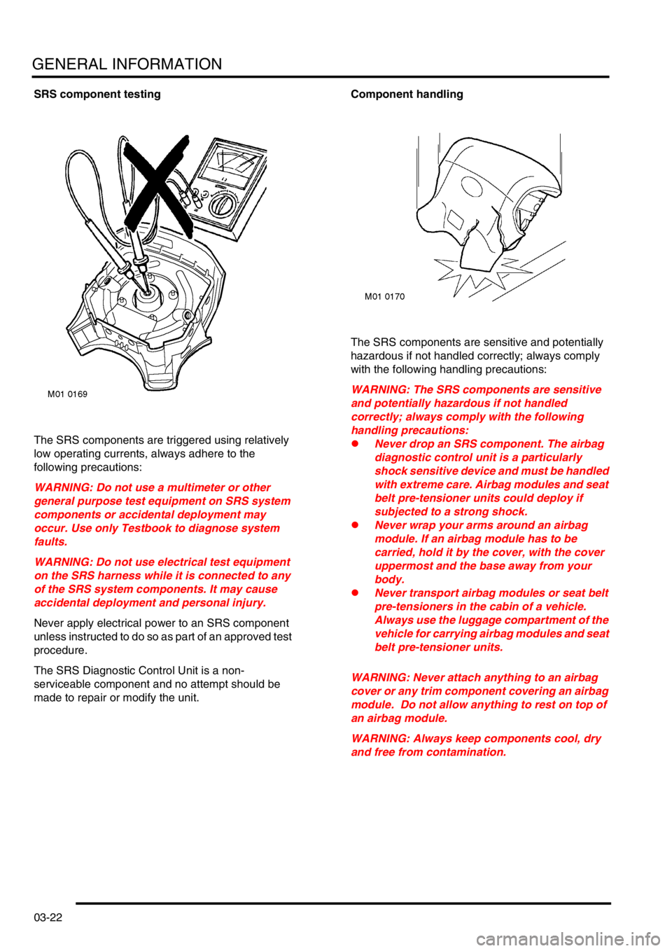
WARNING: Do not use a multimeter or other
general purpose test equipment on SRS system
components or accidental deployment may
occur. Use only Testbook to diagnose system
faults.
WARNING: Do not use electrical test equipment
on the SRS harness while it is connected to any
of the SRS system components. It may cause
accidental deployment and personal injury.
Never apply electrical power to an SRS component
unless instructed to do so as part of an approved test
procedure.
The SRS Diagnostic Control Unit is a non-
serviceable component and no attempt should be
made to repair or modify the unit.Component handling
The SRS components are sensitive and potentially
hazardous if not handled correctly; always comply
with the following handling precautions:
WARNING: The SRS components are sensitive
and potentially hazardous if not handled
correctly; always comply with the following
handling precautions:
lNever drop an SRS component. The airbag
diagnostic control unit is a particularly
shock sensitive device and must be handled
with extreme care. Airbag modules and seat
belt pre-tensioner units could deploy if
subjected to a strong shock.
lNever wrap your arms around an airbag
module. If an airbag module has to be
carried, hold it by the cover, with the cover
uppermost and the base away from your
body.
lNever transport airbag modules or seat belt
pre-tensioners in the cabin of a vehicle.
Always use the luggage compartment of the
vehicle for carrying airbag modules and seat
belt pre-tensioner units.
WARNING: Never attach anything to an airbag
cover or any trim component covering an airbag
module. Do not allow anything to rest on top of
an airbag module.
WARNING: Always keep components cool, dry
and free from contamination.
Page 55 of 1007
GENERAL INFORMATION
03-24
SRS Harnesses and Connectors
CAUTION: Always observe the following
precautions with regards to SRS system
electrical wiring:
lNever attempt to modify, splice or repair
SRS wiring.
lNever install electronic equipment (such as
a mobile telephone, two-way radio or in-car
entertainment system) in such a way that it
could generate electrical interference in the
airbag harness. Seek specialist advice when
installing such equipment.
NOTE: SRS system wiring can be identified by a
special yellow outer sleeve protecting the wires
(black with yellow stripe protective coverings are
sometimes used).
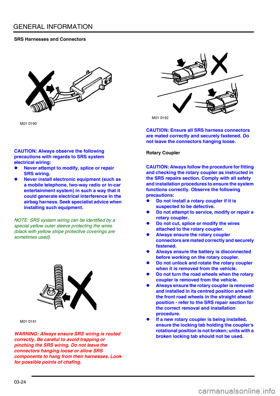
WARNING: Always ensure SRS wiring is routed
correctly. Be careful to avoid trapping or
pinching the SRS wiring. Do not leave the
connectors hanging loose or allow SRS
components to hang from their harnesses. Look
for possible points of chafing.CAUTION: Ensure all SRS harness connectors
are mated correctly and securely fastened. Do
not leave the connectors hanging loose.
Rotary Coupler
CAUTION: Always follow the procedure for fitting
and checking the rotary coupler as instructed in
the SRS repairs section. Comply with all safety
and installation procedures to ensure the system
functions correctly. Observe the following
precautions:
lDo not install a rotary coupler if it is
suspected to be defective.
lDo not attempt to service, modify or repair a
rotary coupler.
lDo not cut, splice or modify the wires
attached to the rotary coupler.
lAlways ensure the rotary coupler
connectors are mated correctly and securely
fastened.
lAlways ensure the battery is disconnected
before working on the rotary coupler.
lDo not unlock and rotate the rotary coupler
when it is removed from the vehicle.
lDo not turn the road wheels when the rotary
coupler is removed from the vehicle.
lAlways ensure the rotary coupler is removed
and installed in its centred position and with
the front road wheels in the straight ahead
position - refer to the SRS repair section for
the correct removal and installation
procedure.
lIf a new rotary coupler is being installed,
ensure the locking tab holding the coupler's
rotational position is not broken; units with a
broken locking tab should not be used.
Page 60 of 1007
GENERAL INFORMATION
03-29
Air conditioning system precautions
General
The air conditioning system contains fluids and
components which could be potentially hazardous to
the service engineer or the environment if not
serviced and handled correctly. The following
guidelines are intended to alert the service engineer
to potential sources of danger and emphasise the
importance of ensuring the integrity of the Air
Conditioning operating conditions and components
fitted to the vehicle.
Where necessary, additional specific precautions are
detailed in the relevant sections of this Manual which
should be referred to prior to commencing repair
operations.
The refrigerant used in the air conditioning system is
HFC-134a (Hydrofluorocarbon) R134a. Always
adhere to the following precautions:
WARNING: Servicing must only be carried out by
personnel familiar with both the vehicle system
and the charging and testing equipment. All
operations must be carried out in a well
ventilated area away from open flame and heat
sources.
WARNING: Do not allow a refrigerant container to
be heated by direct flame or to be placed near
any heating appliance. A refrigerant container
must not be heated above 50
°C.
Do not leave a container of refrigerant without its
cap fitted. Do not transport a container of
refrigerant that is unrestrained, especially in the
boot of a car.
WARNING: Do not smoke or weld in areas where
R134a is in use. Inhalation of concentrations of
vapour can cause dizziness, disorientation,
incoordination, narcosis, nausea or vomiting.
R134a is odourless and colourless. Do not
handle or discharge in an enclosed area, or any
area where the vapour and liquid can come in
contact with a naked flame or hot metal. R134a is
not flammable but can cause a highly toxic gas.
WARNING: Do not allow fluids other than R134a
or compressor lubricant to enter the air
conditioning system. Spontaneous combustion
may occur.WARNING: R134a is a hazardous liquid and when
handled incorrectly can cause serious injury.
Suitable protective clothing, consisting of face
protection, heat proof gloves, rubber boots and
rubber apron or waterproof overalls, must be
worn when carrying out operations on the air
conditioning system.
WARNING: Due to its low evaporating
temperature, R134a must be handled with care.
R134a splashed on any part of the body will
cause immediate freezing of that area. Also,
refrigerant cylinders and replenishment trolleys
when discharging will freeze skin to them if
contact is made.
WARNING: Under no circumstances should
refrigerant hoses be disconnected without first
discharging the system.
Do not disconnect any pipes in an air
conditioning refrigeration system unless trained
and instructed to do so. A refrigerant is used
which can cause blindness if allowed to contact
eyes.
WARNING: Refrigerant must always be recycled
before re-use to ensure that the purity of the
refrigerant is high enough for safe use in the air
conditioning system.
Recycling should always be carried out with
equipment which is design certified by
Underwriter Laboratory Inc. for compliance with
SAE J1991. Other equipment may not recycle
refrigerant to the required level of purity.
A R134a Refrigerant Recovery Recycling
Recharging Station must not be used with any
other type of refrigerant.
Refrigerant R134a from domestic and
commercial sources must not be used in motor
vehicle air conditioning systems.
Page 61 of 1007

GENERAL INFORMATION
03-30
Remedial actions
If an accident involving R134a should occur, conduct
the following remedial actions:
lIf liquid R134a enters the eye, do not rub it.
Gently run large quantities of eye wash over
affected eye to raise the temperature. If an eye
wash is not available, cool clean water may be
used to flush the eye. After rinsing, cover the
eye with a clean pad and seek immediate
medical attention.
lIf liquid R134a is splashed onto the skin, run
large quantities of water over the affected area
to raise the temperature. Implement the same
action if the skin comes in contact with
discharging cylinders. Wrap the contaminated
body parts in blankets (or similar materials) and
seek immediate medical attention.
lIf the debilitating effects of inhalation of R134a
vapour is suspected, seek fresh air. If the
affected person is unconscious, move them
away from the contaminated area to fresh air
and apply artificial respiration and/or oxygen
and seek immediate medical attention.
Service precautions
Observe the following precautions when handling
components used in the air conditioning system:
lAir conditioning units must not be lifted by their
hoses, pipes or capillary lines.
lHoses and lines must not be subjected to any
twist or stress - the efficiency of the system will
be impaired by kinks or restrictions. Ensure that
hoses are correctly positioned before tightening
couplings, and ensure that all clips and supports
are utilised.
lFlexible hoses should not be positioned close to
the exhaust manifold (less than 100mm) unless
protected by heat shielding.
lCompleted assemblies must be checked for
refrigeration lines touching metal panels. Any
direct contact of components and panels may
transmit noise and so must be eliminated.
lThe appropriate torque wrench must be used
when tightening refrigerant connections to the
stipulated value. An additional spanner must be
used to hold the union to prevent twisting of the
pipe when tightening connections.
lBefore connecting any hose or pipe, ensure that
refrigerant oil is applied to the seat of the new
'O' ring seals, BUT NOT to the threads of the
connection.
lAll protective plugs must remain in place to seal
the component until immediately prior to
connection.
lEnsure components are at room temperature
before uncapping, to prevent condensation of
moisture from the air that enters it.
lComponents must not remain uncapped for
longer than 15 minutes. In the event of a delay,
the caps must be fitted.
lWhen disconnecting, immediately cap all air
conditioning pipes to prevent ingress of dirt and
moisture into the system.
lThe modulator (receiver/drier) contains
desiccant which absorbs moisture. It must be
positively sealed at all times. A modulator that
has been left uncapped must not be used, fit a
new unit.
lThe modulator should be the last component
connected to the system to ensure optimum
dehydration and maximum moisture protection
of the system.
lWhenever the refrigerant system is opened, the
modulator must be renewed immediately before
evacuating and recharging the system.
lUse alcohol and a clean lint-free cloth to clean
dirty connections.
lEnsure that all new parts fitted are marked for
use with R134a.
Page 70 of 1007

GENERAL DATA
04-7
Cylinder head
Material Aluminium alloy
Cylinder head warp - maximum 0.05 mm (0.002 in)
Cylinder head height:
⇒ New 118.95 - 119.05 mm (4.683 - 4.687 in.)
⇒ Reface limit 0.20 mm (0.008 in.)
Crankshaft
Crankshaft end-float 0.10 - 0.25 mm (0.004 - 0.010 in.)
⇒ Service limit 0.34 mm (0.013 in.)
Main journal diameter: 47.986 - 48.007 mm (1.8892 - 1.8900 in.)
⇒ Maximum out of round 0.010 mm (0.0004 in.)
Main journal tolerance:
⇒ Grade 1 48.000 - 48.007 mm (1.8898 - 1.8900 in.)
⇒ Grade 2 47.993 - 48.000 mm (1.8895 - 1.8898 in.)
⇒ Grade 3 47.986 - 47.993 mm (1.8892 - 1.8895 in.)
Big-end journal diameter 47.986 - 48.007 mm (1.8892 - 1.8900 in.)
⇒ Maximum out of round 0.010 mm (0.0004 in.)
Big-end journal tolerance:
⇒ Grade A 48.000 - 48.007 mm (1.8898 - 1.8900 in.)
⇒ Grade B 47.993 - 48.000 mm (1.8895 - 1.8898 in.)
⇒ Grade C 47.986 - 47.993 mm (1.8892 - 1.8898 in.)
Main bearings:
Quantity 5
Type Steel backed, aluminium/tin lined, oil grooves in upper halves, plain in
bearing caps
Clearance in bearings 0.02 - 0.05 mm (0.0008 - 0.0020 in.)
Thrust washers Halves at No.3 main bearing
Thrust washer halves thickness 2.61 - 2.65 mm (0.1028 - 1.043 in.)
Big-end bearings:
Clearance in bearings 0.021 - 0.049 mm (0.0008 - 0.0019 in.)
Big-end end-float 0.10 - 0.25 mm (0.004 - 0.010 in.)
Connecting rods:
Type Horizontally split big-end, plain small end
Distance between centres 133.05 - 133.15 mm (5.238 - 5.242 in.)
Gudgeon pins:
Type Semi-floating off-set towards thrust side
⇒ Fit in connecting rod Interference
⇒ Diameter (RED) 17.997 - 18.000 mm (0.7085 - 0.7087 in.)
⇒ Diameter (GREEN) 17.994 - 17.997 mm (0.7084 - 0.7087 in.)
⇒ Length 52.3 - 52.6 mm (2.06 - 2.07 in.) General