service LAND ROVER FREELANDER 2001 Workshop Manual
[x] Cancel search | Manufacturer: LAND ROVER, Model Year: 2001, Model line: FREELANDER, Model: LAND ROVER FREELANDER 2001Pages: 1007, PDF Size: 23.47 MB
Page 1 of 1007
Workshop Manual
Service Procedures
Page 2 of 1007
FREELANDER 2001MY ON
WORKSHOP MANUAL - SERVICE
PROCEDURES
Publication Part No. LRL0490 NAS - 5th Edition
© Land Rover 2003
All rights reserved. No part of this publication may be reproduced, stored in a retrieval system or transmitted in any form,
electronic, mechanical, recording or other means without prior written permission from Land Rover.
Page 4 of 1007
CONTENTS
CONTENTS 1
INTRODUCTION ...................................................................................... 01-1
How To Use This Manual................................................................................................................ 01-1
Repairs and Replacements ............................................................................................................. 01-2
Specifications .................................................................................................................................. 01-2
Abbreviations and Symbols ............................................................................................................ 01-3
GENERAL INFORMATION ...................................................................... 03-1
General precautions ........................................................................................................................ 03-1
Safety instructions ........................................................................................................................... 03-2
Environmental Precautions ............................................................................................................. 03-3
General fitting instructions .............................................................................................................. 03-7
Ball and roller bearings ................................................................................................................... 03-8
Oil seals .......................................................................................................................................... 03-9
Joints and joint faces ...................................................................................................................... 03-10
Locking devices .............................................................................................................................. 03-10
Screw threads ................................................................................................................................. 03-11
Bolt identification ............................................................................................................................. 03-12
Nut identification ............................................................................................................................. 03-13
Flexible pipes and hoses ................................................................................................................ 03-14
Service tools ................................................................................................................................... 03-16
Rolling road testing ......................................................................................................................... 03-17
Fuel handling precautions ............................................................................................................... 03-18
Electrical precautions ...................................................................................................................... 03-19
Supplementary restraint system precautions .................................................................................. 03-20
SRS component manual deployment ............................................................................................. 03-27
SRS component replacement policy ............................................................................................... 03-28
Air conditioning system precautions ............................................................................................... 03-29
Remedial actions ............................................................................................................................ 03-30
Service precautions ........................................................................................................................ 03-30
Air conditioning compressor replacement ....................................................................................... 03-31
Page 7 of 1007
CONTENTS
4CONTENTS
MAINTENANCE ........................................................................................ 10-1
MAINTENANCE
Td4 - Diesel Engine - Under Bonnet View ...................................................................................... 10-1
K1.8 – Petrol Engine – Under Bonnet View .................................................................................... 10-2
KV6 – Petrol Engine – Under Bonnet View .................................................................................... 10-3
Seats and Seat Belts ...................................................................................................................... 10-4
Lamps, Horns and Warning Indicators ........................................................................................... 10-4
Wipers and Washers ...................................................................................................................... 10-5
Handbrake ...................................................................................................................................... 10-5
Alarm Handset Battery.................................................................................................................... 10-6
Road Wheels .................................................................................................................................. 10-6
Tyres ............................................................................................................................................... 10-7
Brake Pads and Calipers ................................................................................................................ 10-7
Brake Fluid...................................................................................................................................... 10-9
Road Wheel Speed Sensors .......................................................................................................... 10-9
Fuel Filter - Petrol ........................................................................................................................... 10-10
Fuel Filter - Diesel........................................................................................................................... 10-10
Fuel Pump and Filter assembly - Diesel - 03 Model Year onwards ................................................ 10-10
Fuel Sedimenter - Diesel - 03 Model Year onwards ....................................................................... 10-10
Door Locks, Hinges, Check Straps and Bonnet Catch ................................................................... 10-11
Anti-freeze ...................................................................................................................................... 10-12
Cooling System and Intercooler...................................................................................................... 10-12
Vent filter - turbocharger boost control solenoid valve - Td4 .......................................................... 10-13
Spark Plugs – K1.8 ......................................................................................................................... 10-13
Spark Plugs – KV6.......................................................................................................................... 10-13
Air Cleaner – Petrol Models ............................................................................................................ 10-13
Ancillary Drive Belt – Td4 ............................................................................................................... 10-14
Ancillary Drive Belt – K1.8 .............................................................................................................. 10-14
Ancillary Drive Belt – KV6 ............................................................................................................... 10-15
Camshaft Timing Belt – K1.8 .......................................................................................................... 10-15
Camshaft Timing Belt – KV6........................................................................................................... 10-16
Brake/Clutch Reservoir ................................................................................................................... 10-16
PAS Fluid Level .............................................................................................................................. 10-17
Intermediate Reduction Drive - Non NAS models .......................................................................... 10-17
Intermediate Reduction Drive - NAS models .................................................................................. 10-18
Manual Gearbox – PG1 .................................................................................................................. 10-18
Manual Gearbox – GETRAG .......................................................................................................... 10-19
Automatic Gearbox – JATCO ......................................................................................................... 10-19
Rear Axle ........................................................................................................................................ 10-20
Clutch Pipes and Unions ................................................................................................................ 10-21
Windscreen and Rear Washer Reservoir ....................................................................................... 10-21
Battery ............................................................................................................................................ 10-21
Engine Oil and Filter – Td4 ............................................................................................................. 10-22
Engine Oil and Filter – K1.8 ............................................................................................................ 10-23
Engine Oil and Filter – KV6 ............................................................................................................ 10-24
Fuel Hoses and Pipes..................................................................................................................... 10-25
Brake Hoses and Pipes ................................................................................................................. 10-26
Check Exhaust System................................................................................................................... 10-26
Suspension ..................................................................................................................................... 10-27
Steering ......................................................................................................................................... 10-28
Road Test ....................................................................................................................................... 10-28
Endorse Service Record ................................................................................................................. 10-30
Report any Unusual Features ......................................................................................................... 10-30
Page 19 of 1007
CONTENTS
16 CONTENTS
PANEL REPAIRS...................................................................................... 77-2-1
BODY REPAIRS
General ........................................................................................................................................... 77-2-1
REPLACEMENT PANELS
Serviceable Panels ......................................................................................................................... 77-2-3
Inner front end panels ..................................................................................................................... 77-2-4
Outer body side panels - 3 door ..................................................................................................... 77-2-5
Outer body side panels - 5 door ..................................................................................................... 77-2-6
Front inner body side panels - 3 door ............................................................................................. 77-2-7
Front inner body side panels - 5 door ............................................................................................. 77-2-8
Rear inner body side panels - 3 door.............................................................................................. 77-2-9
Rear inner body side panels - 5 door.............................................................................................. 77-2-10
Roof assemblies - 3 door ................................................................................................................ 77-2-11
Roof assembly - 5 door................................................................................................................... 77-2-12
Rear end panels ............................................................................................................................. 77-2-13
Door assemblies ............................................................................................................................. 77-2-14
WELDING PROCEDURES
ECU locations (3 door model shown, 5 door model similar) ........................................................... 77-2-15
General Welding Precautions ......................................................................................................... 77-2-16
PROCEDURES
Panel replacement procedure......................................................................................................... 77-2-19
REPAIRS
Front bulkhead assembly ............................................................................................................... 77-2-25
Bonnet locking platform .................................................................................................................. 77-2-27
Headlamp mounting panel .............................................................................................................. 77-2-28
Front lower crossmember .............................................................................................................. 77-2-29
Front sidemember (complete) ........................................................................................................ 77-2-30
Front sidemember (front section) ................................................................................................... 77-2-32
Front valance assembly ................................................................................................................. 77-2-33
Valance upper front ....................................................................................................................... 77-2-36
Valance front .................................................................................................................................. 77-2-37
Valance outer reinforcement .......................................................................................................... 77-2-39
'A' post - 3 door .............................................................................................................................. 77-2-40
'A' post - 5 door .............................................................................................................................. 77-2-41
Sill reinforcement - 3 door .............................................................................................................. 77-2-43
Sill reinforcement - 5 door .............................................................................................................. 77-2-44
'B/C' post reinforcement - 3 door ................................................................................................... 77-2-45
'B/C' post reinforcement - 5 door ................................................................................................... 77-2-46
Complete rear quarter - 3 door ...................................................................................................... 77-2-48
Complete rear quarter - 5 door ...................................................................................................... 77-2-50
Outer rear wheel arch - 3 door ....................................................................................................... 77-2-53
Outer rear wheel arch - 5 door ....................................................................................................... 77-2-54
Inner 'e' post - 3 door ..................................................................................................................... 77-2-55
Inner 'e' post - 5 door ..................................................................................................................... 77-2-56
Rear floor crossmember assembly ................................................................................................ 77-2-58
Rear floor ........................................................................................................................................ 77-2-59
Floor longitudinal ............................................................................................................................ 77-2-60
Front roof assembly - 3 door .......................................................................................................... 77-2-61
Rear roof assembly - 3 door .......................................................................................................... 77-2-61
Roof assembly - 5 door .................................................................................................................. 77-2-62
TIMES
TIME SCHEDULES ........................................................................................................................ 77-2-63
Page 26 of 1007
INTRODUCTION
01-1
INTRODUCTION
How To Use This Manual
General
To assist in the use of this Manual, it is divided into
sections and sub-sections. The section title is given
at the top of each page and the relevant sub-section
is given at the bottom.
There is a single contents section at the front of the
Manual, which is divided by section and sub-section.
Each section is numbered from page 1.
The individual items comprising repair operations are
to be followed in the sequence in which they appear.
Item numbers shown in illustrations are referred to in
the associated text.
Adjustment, Repair and Overhaul operations include
reference to Service tool numbers and the
associated illustration depicts the tool in use.
Adjustment and repair operations also include
reference to wear limits, relevant data, torque
figures, specialist information and useful assembly
details. Each adjustment or repair operation is given
a Service Repair Operation (SRO) number.
WARNINGS, CAUTIONS and NOTES have the
following meanings:
WARNING: Procedures which must be followed
precisely to avoid the possibility of injury.
CAUTION: Calls attention to procedures which
must be followed to avoid damage to
components.
NOTE: Gives helpful information.
References
References to the LH or RH side given in this Manual
are made when viewing the vehicle from the rear.
With the engine and gearbox assembly removed, the
crankshaft pulley end of the engine is referred to as
the front.
Operations covered in this Manual do not include
reference to testing the vehicle after repair. It is
essential that work is inspected and tested after
completion and if necessary a road test of the vehicle
is carried out. This is of particular importance where
safety related items are concerned.
Dimensions
The dimensions quoted are to design engineering
specification. Service limits are included where
applicable.Electrical Reference Library (ERL) and Circuit
Diagrams
The Electrical Reference Library (ERL) and Circuit
Diagrams are separate publications intended for use
by trained Land Rover technicians and should be
referred to when attempting to diagnose electrically
related concerns.
The ERL contains descriptions of how the circuits
operate, fuse details, earth point locations, and a
definitive guide to the attributes and location of every
connector on the vehicle.
The ERL is used in conjunction with the Circuit
Diagrams. Both publications are designed to support
all aspects of electrical fault diagnosis.
TESTBOOK (Fault Diagnostic Equipment)
Freelander is equipped with a number of electronic
control systems to provide optimum performance of
the vehicle's systems.
Diagnostic equipment (TESTBOOK/T4) is available
to assist with the fault diagnostic abilities of the
dealer workshop. In particular, the equipment can be
used to interrogate the Engine Control Module
(ECM) for diagnosis of emissions related faults which
may become evident by the illumination of the
Malfunction Indicator Lamp (MIL) in the instrument
pack. This feature is included in compliance with the
latest emissions legislation pertinent to a particular
market (e.g. EU3 for Europe, OBDII for North
America etc.).
This repair manual is produced as a reference
source to supplement Testbook/T4. When available,
the equipment should be used as the primary means
of fault diagnosis on electronically controlled
systems.
Features of TestbookT4 include:
lFully upgradable support for the technician
lStructured diagnostics to accommodate all skill
levels.
lTouch screen operation - Testbook only.
lDirect print out of screen information and test
results.
Page 29 of 1007
INTRODUCTION
01-4
HRW Heated Rear Window
ht/HT High tension
HSLA High Strength Low Alloy
IACV Idle Air Control Valve
IAT Intake Air Temperature
ICE In-Car Entertainment
i.dia. Internal diameter
IDM Intelligent Driver Module
IF Intermediate Frequency
in Inch
in
2Square inch
in3Cubic inch
ILT Inlet Throttle
ISO International Organisation for
Standardisation
ITS Inflatable Tubular Structure
k Thousand
kg Kilogramme
kg/h Kilogrammes per hour
km Kilometre
km/h Kilometres per hour
kPa KiloPascal
KS Knock Sensor
lb(s) Pounds
lbf Pounds force
lbf.in Pounds force inches
lbf/in
2Pounds per square inch
lbf.ft Pounds force feet
λLambda
lc Low compression
LCD Liquid Crystal Display
LED Light Emitting Diode
LEV Low Emission Vehicle
LH Left-Hand
LHD Left-Hand Drive
LSM Light Switch Module
LVS Liquid Vapour Separator
mMetre
µMicro
MAF Mass Air Flow
MAP Manifold Absolute Pressure
MFU Multi-Function Unit
MFL Multi-Function Logic
max. Maximum
MEMS Modular Engine Management
System
MIG Metal/Inert Gas
MIL Malfunction Indicator Lamp
MPa MegaPascal
MOSFET Metal Oxide Semiconductor Field
Effect Transistor
min. Minimum
- Minus (tolerance)
' Minute (angle)
mm Millimetre
mph Miles per hour MPi Multi-Point injection
MV Motorised Valve
MY Model Year
NAS North American Specification
(-) Negative (electrical)
Nm Newton metre
No. Number
NO
2Nitrogen Dioxide
NO
xOxides of Nitrogen
NTC Negative Temperature
Coefficient
NRV Non Return Valve
OBD On Board Diagnostics
OBM On Board Monitoring
o.dia. Outside diameter
OAT Organic Acid Technology
ORM Off-road Mode
ΩOhm
PAS Power Assisted Steering
PCB Printed Circuit Board
PCV Positive Crankcase Ventilation
PDC Parking Distance Control
PDOP Position Dilation Of Precision
PI Programme Information
PPS Pulse Per Second
PS Programme Service
psi Pounds per square inch
pts. Pints
% Percentage
+ Plus (tolerance) or Positive
(electrical)
±Plus or minus (tolerance)
PTC Positive Temperature Coefficient
PTFE Polytetrafluorethylene
PWM Pulse Width Modulation
RDS Radio Data Service
rRadius
:Ratio
ref Reference
REG Regionalisation
RES Rover Engineering Standards
rev/min Revolutions per minute
RF Radio Frequency
RGB Red / Green / Blue
RH Right-Hand
RHD Right-Hand Drive
ROM Read Only Memory
RON Research Octane Number
ROV Roll Over Valve
ROW Rest Of World
SAE Society of Automotive Engineers
SAI Secondary Air Injection
" Second (angle)
SLABS Self Levelling and Anti-Lock
Brake System
SLS Self Levelling Suspension
SOHC Single Overhead Camshaft
SPE Single Point Entry
Page 38 of 1007
GENERAL INFORMATION
03-7
General fitting instructions
Precautions against damage
To avoid damage to the vehicle when carrying out
repairs, always adhere to the following:
lAlways fit wing and seat covers before
commencing work. Avoid spilling brake fluid or
battery acid on paintwork; immediately wash off
with water if this occurs.
lDisconnect the battery earth lead before starting
work, see ELECTRICAL PRECAUTIONS.
lAlways use the recommended service tool or a
satisfactory equivalent where specified.
lProtect exposed bearing surfaces, sealing
surfaces and screw threads from damage.
Component removal
Whenever possible, clean components and
surrounding area before removal.
lBlank off openings exposed by component
removal.
lImmediately seal fuel, oil or hydraulic lines when
apertures are exposed; use plastic caps or
plugs to prevent loss of fluid and ingress of dirt.
lClose open ends of oilways exposed by
component removal with tapered hardwood
plugs or conspicuous plastic plugs.
lImmediately a component is removed, place it in
a suitable container; use a separate container
for each component and its associated parts.
lClean bench and provide marking materials,
labels, containers and locking wire before
dismantling a component.
Dismantling
Observe scrupulous cleanliness when dismantling
components, particularly when brake, fuel or
hydraulic system parts are being worked on. A
particle of dirt or a cloth fragment could cause a
serious malfunction if trapped in these systems.Use the following procedures:
lBlow out all tapped holes, crevices, oilways and
fluid passages with an air line. Ensure that any
O-rings used for sealing are correctly replaced
or renewed if disturbed during the process.
lUse marking ink to identify mating parts and
ensure correct reassembly. Do not use a centre
punch or scriber to mark parts, they could
initiate cracks or distortion in marked
components.
lWire together mating parts where necessary to
prevent accidental interchange (e.g. roller
bearing components).
lWire labels on to all parts which are to be
renewed, and to parts requiring further
inspection before being passed for reassembly;
place these parts in separate containers from
those containing parts for rebuild.
lDo not discard a part due for renewal until after
comparing it with a new part to ensure that its
correct replacement has been obtained.
Cleaning components
Always use the recommended cleaning agent or
equivalent. Ensure that adequate ventilation is
provided when volatile degreasing agents are being
used. Do not use degreasing equipment for
components containing items which could be
damaged by the use of this process.
When washing under bonnet, never direct water onto
ECM, as water ingress may occur resulting in
damage to electrical components inside.
General Inspection
All components should be inspected for wear or
damage before being reassembled.
lNever inspect a component for wear or
dimensional check unless it is absolutely clean;
a slight smear of grease can conceal an
incipient failure.
lWhen a component is to be checked
dimensionally against recommended values,
use the appropriate measuring equipment
(surface plates, micrometers, dial gauges etc.).
Ensure the measuring equipment is calibrated
and in good serviceable condition.
lReject a component if its dimensions are
outside the specified tolerances, or if it appears
to be damaged.
lA part may be refitted if its critical dimension is
exactly to its tolerance limit and it appears to be
in satisfactory condition.
lUse 'Plastigauge' 12 Type PG-1 for checking
bearing surface clearances.
Page 39 of 1007
GENERAL INFORMATION
03-8
Ball and roller bearings
General
When removing and installing bearings, ensure that
the following practices are observed to ensure
component serviceability:
lRemove all traces of lubricant from the bearing
under inspection by cleaning with a suitable
degreasant; maintain absolute cleanliness
throughout operations.
lConduct a visual inspection for markings on
rolling elements, raceways, outer surface of
outer rings or inner surface of inner rings. Reject
any bearings found to be marked, since marking
in these areas indicates onset of wear.
lHold inner race of bearing between finger and
thumb of one hand and spin outer race to check
that it revolves absolutely smoothly. Repeat,
holding outer race and spinning inner race.
lRotate outer ring gently with a reciprocating
motion, while holding inner ring; feel for any
check or obstruction to rotation. Reject bearing
if action is not perfectly smooth.
lLubricate bearing with generous amounts of
lubricant appropriate to installation.
lInspect shaft and bearing housing for
discoloration or other markings which indicate
movement between bearing and seatings.
lEnsure that shaft and housing are clean and
free from burrs before fitting bearing.
lIf one bearing of a pair shows an imperfection, it
is advisable to replace both with new bearings;
an exception could be if the faulty bearing had
covered a low mileage, and it can be
established that damage is confined to only one
bearing.
lNever refit a ball or roller bearing without first
ensuring that it is in a fully serviceable condition.
lWhen hub bearings are removed or displaced,
NEW bearings must be fitted; do not attempt to
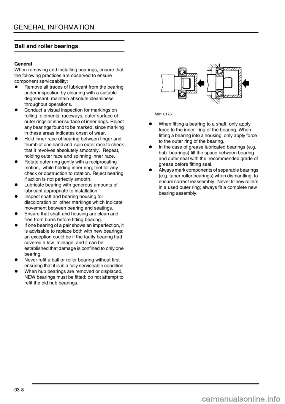
refit the old hub bearings.lWhen fitting a bearing to a shaft, only apply
force to the inner ring of the bearing. When
fitting a bearing into a housing, only apply force
to the outer ring of the bearing.
lIn the case of grease lubricated bearings (e.g.
hub bearings) fill the space between bearing
and outer seal with the recommended grade of
grease before fitting seal.
lAlways mark components of separable bearings
(e.g. taper roller bearings) when dismantling, to
ensure correct reassembly. Never fit new rollers
in a used outer ring; always fit a complete new
bearing assembly.
Page 40 of 1007
GENERAL INFORMATION
03-9
Oil seals
General
Always renew oil seals which have been removed
from their working location (whether as an individual
component or as part of an assembly). NEVER use
a seal which has been improperly stored or handled,
such as hung on a hook or nail.
lCarefully examine seal before fitting to ensure
that it is clean and undamaged.
lEnsure the surface on which the new seal is to
run is free of burrs or scratches. Renew the
component if the original sealing surface cannot
be completely restored.
lProtect the seal from any surface which it has to
pass when being fitted. Use a protective sleeve
or tape to cover the relevant surface.
lCertain oil seals are coated with a protective
wax and must be fitted dry unless stated
otherwise. Where an oil seal needs to be
lubricated prior to fitment, lubricate the sealing
lips with a recommended lubricant before use to
prevent damage during initial use. On dual
lipped seals, smear the area between the lips
with grease.
lIf a seal spring is provided, ensure that it is fitted
correctly.
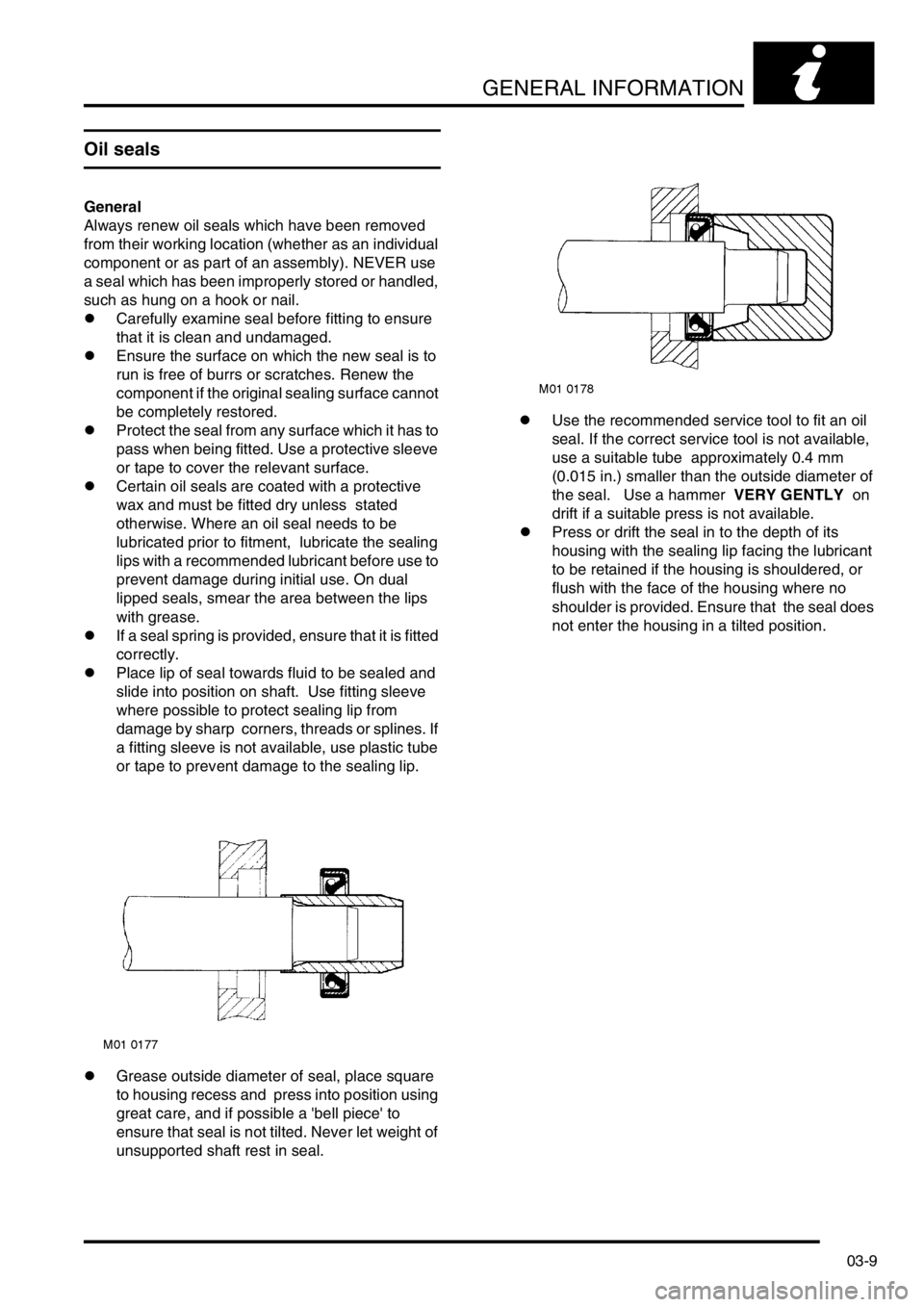
lPlace lip of seal towards fluid to be sealed and
slide into position on shaft. Use fitting sleeve
where possible to protect sealing lip from
damage by sharp corners, threads or splines. If
a fitting sleeve is not available, use plastic tube
or tape to prevent damage to the sealing lip.
lGrease outside diameter of seal, place square
to housing recess and press into position using
great care, and if possible a 'bell piece' to
ensure that seal is not tilted. Never let weight of
unsupported shaft rest in seal.lUse the recommended service tool to fit an oil
seal. If the correct service tool is not available,
use a suitable tube approximately 0.4 mm
(0.015 in.) smaller than the outside diameter of
the seal. Use a hammer VERY GENTLY on
drift if a suitable press is not available.
lPress or drift the seal in to the depth of its
housing with the sealing lip facing the lubricant
to be retained if the housing is shouldered, or
flush with the face of the housing where no
shoulder is provided. Ensure that the seal does
not enter the housing in a tilted position.