fuel low LAND ROVER FREELANDER 2001 Service Manual
[x] Cancel search | Manufacturer: LAND ROVER, Model Year: 2001, Model line: FREELANDER, Model: LAND ROVER FREELANDER 2001Pages: 1007, PDF Size: 23.47 MB
Page 346 of 1007
FUEL DELIVERY SYSTEM - PETROL
REPAIRS 19-2-25
Sensor - heated oxygen (H02S) - post
catalyst - LH - KV6 - NAS
$% 19.22.71
Remove
1.Disconnect battery earth lead.
2.Raise front of vehicle and support on stands.
WARNING: Do not work on or under a
vehicle supported only by a jack. Always
support the vehicle on safety stands.
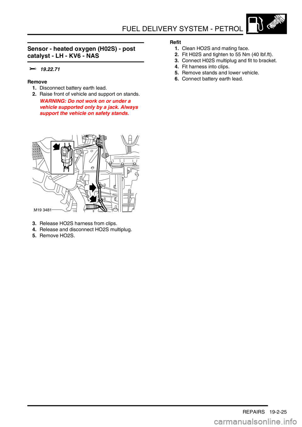
3.Release HO2S harness from clips.
4.Release and disconnect HO2S multiplug.
5.Remove HO2S.Refit
1.Clean HO2S and mating face.
2.Fit H02S and tighten to 55 Nm (40 lbf.ft).
3.Connect H02S multiplug and fit to bracket.
4.Fit harness into clips.
5.Remove stands and lower vehicle.
6.Connect battery earth lead.
M19 3481
Page 347 of 1007
FUEL DELIVERY SYSTEM - PETROL
19-2-26 REPAIRS
Sensor - heated oxygen (H02S) - post cat
- K1.8
$% 19.22.71
Remove
1.Raise front of vehicle.
WARNING: Do not work on or under a
vehicle supported only by a jack. Always
support the vehicle on safety stands.
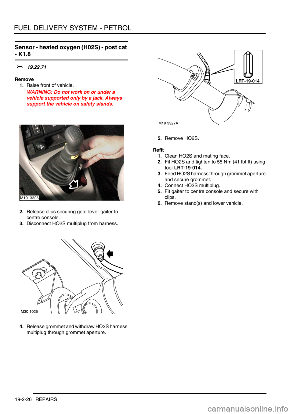
2.Release clips securing gear lever gaiter to
centre console.
3.Disconnect HO2S multiplug from harness.
4.Release grommet and withdraw HO2S harness
multiplug through grommet aperture.5.Remove HO2S.
Refit
1.Clean HO2S and mating face.
2.Fit HO2S and tighten to 55 Nm (41 lbf.ft) using
tool LRT-19-014.
3.Feed HO2S harness through grommet aperture
and secure grommet.
4.Connect HO2S multiplug.
5.Fit gaiter to centre console and secure with
clips.
6.Remove stand(s) and lower vehicle.
M19 3325
Page 348 of 1007
FUEL DELIVERY SYSTEM - PETROL
REPAIRS 19-2-27
Sensor - heated oxygen (H02S) - post
catalyst - RH - KV6 - NAS
$% 19.22.72
Remove
1.Disconnect battery earth lead.
2.Raise vehicle on 4 post ramp.
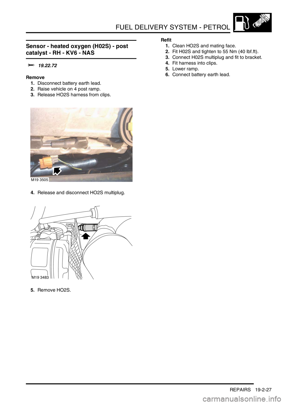
3.Release HO2S harness from clips.
4.Release and disconnect HO2S multiplug.
5.Remove HO2S.Refit
1.Clean HO2S and mating face.
2.Fit H02S and tighten to 55 Nm (40 lbf.ft).
3.Connect H02S multiplug and fit to bracket.
4.Fit harness into clips.
5.Lower ramp.
6.Connect battery earth lead.
M19 3505
M19 3483
Page 350 of 1007
FUEL DELIVERY SYSTEM - PETROL
REPAIRS 19-2-29
Pump - fuel
$% 19.45.08
WARNING: If fuel tank is full, using a fuel
recovery appliance, drain excess fuel from fuel
filler neck until a level below height of fuel pump
is obtained.
Remove
1.Disconnect battery earth lead.
2.Open RH rear and tail doors.
3.Fold RH rear seat forward.
4.Remove 2 fasteners securing front and rear
carpets.
5.Pull back loadspace carpet from fuel pump
access panel.
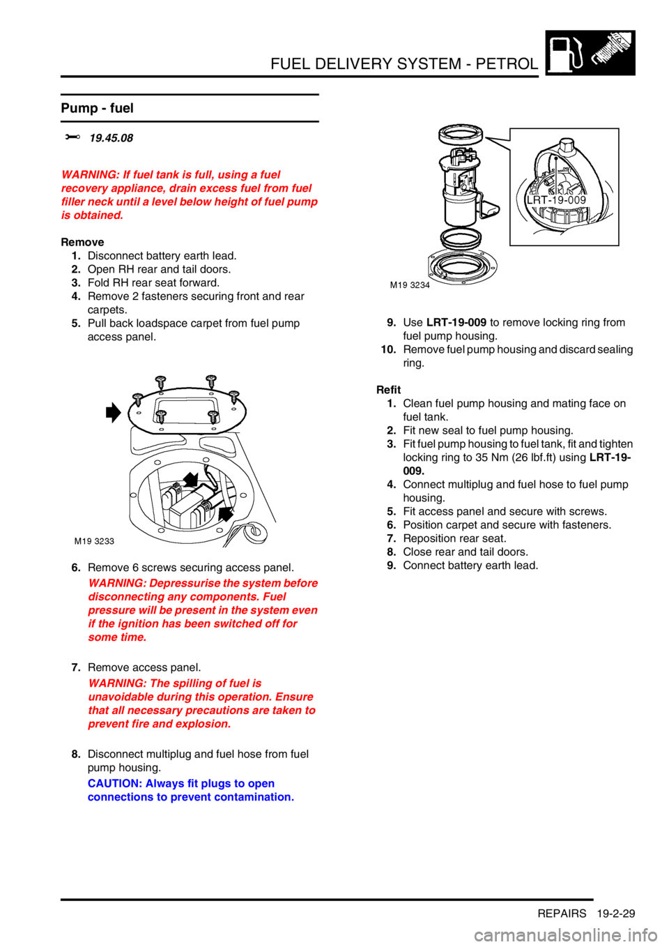
6.Remove 6 screws securing access panel.
WARNING: Depressurise the system before
disconnecting any components. Fuel
pressure will be present in the system even
if the ignition has been switched off for
some time.
7.Remove access panel.
WARNING: The spilling of fuel is
unavoidable during this operation. Ensure
that all necessary precautions are taken to
prevent fire and explosion.
8.Disconnect multiplug and fuel hose from fuel
pump housing.
CAUTION: Always fit plugs to open
connections to prevent contamination.9.Use LRT-19-009 to remove locking ring from
fuel pump housing.
10.Remove fuel pump housing and discard sealing
ring.
Refit
1.Clean fuel pump housing and mating face on
fuel tank.
2.Fit new seal to fuel pump housing.
3.Fit fuel pump housing to fuel tank, fit and tighten
locking ring to 35 Nm (26 lbf.ft) using LRT-19-
009.
4.Connect multiplug and fuel hose to fuel pump
housing.
5.Fit access panel and secure with screws.
6.Position carpet and secure with fasteners.
7.Reposition rear seat.
8.Close rear and tail doors.
9.Connect battery earth lead.
Page 351 of 1007
FUEL DELIVERY SYSTEM - PETROL
19-2-30 REPAIRS
Tank - Non NAS
$% 19.55.01
Remove
1.Position vehicle on ramp.
2.Disconnect battery earth lead.
3.Remove fuel pump assembly.
+ FUEL DELIVERY SYSTEM -
PETROL, REPAIRS, Pump - fuel.
WARNING: The spilling of fuel is
unavoidable during this operation. Ensure
that all necessary precautions are taken to
prevent fire and explosion.
4.Using a fuel recovery appliance, drain the fuel
from the tank into a sealed container. Follow
the manufacturer's instructions for the
connection and safe use of the appliance.
WARNING: The fuel tank must be drained
before it is removed from the vehicle.
5.Remove intermediate exhaust pipe.
+ MANIFOLDS & EXHAUST SYSTEMS
- K SERIES 1.8, REPAIRS, Exhaust pipe -
intermediate.
+ MANIFOLDS & EXHAUST SYSTEMS
- K SERIES KV6, REPAIRS, Intermediate
pipe - Non NAS.
6.Remove propeller shaft.
+ DRIVESHAFTS, REPAIRS, Propeller
shaft assembly.
7.Remove RH rear wheel arch liner.
+ EXTERIOR FITTINGS, REPAIRS,
Liner - rear wheel arch.
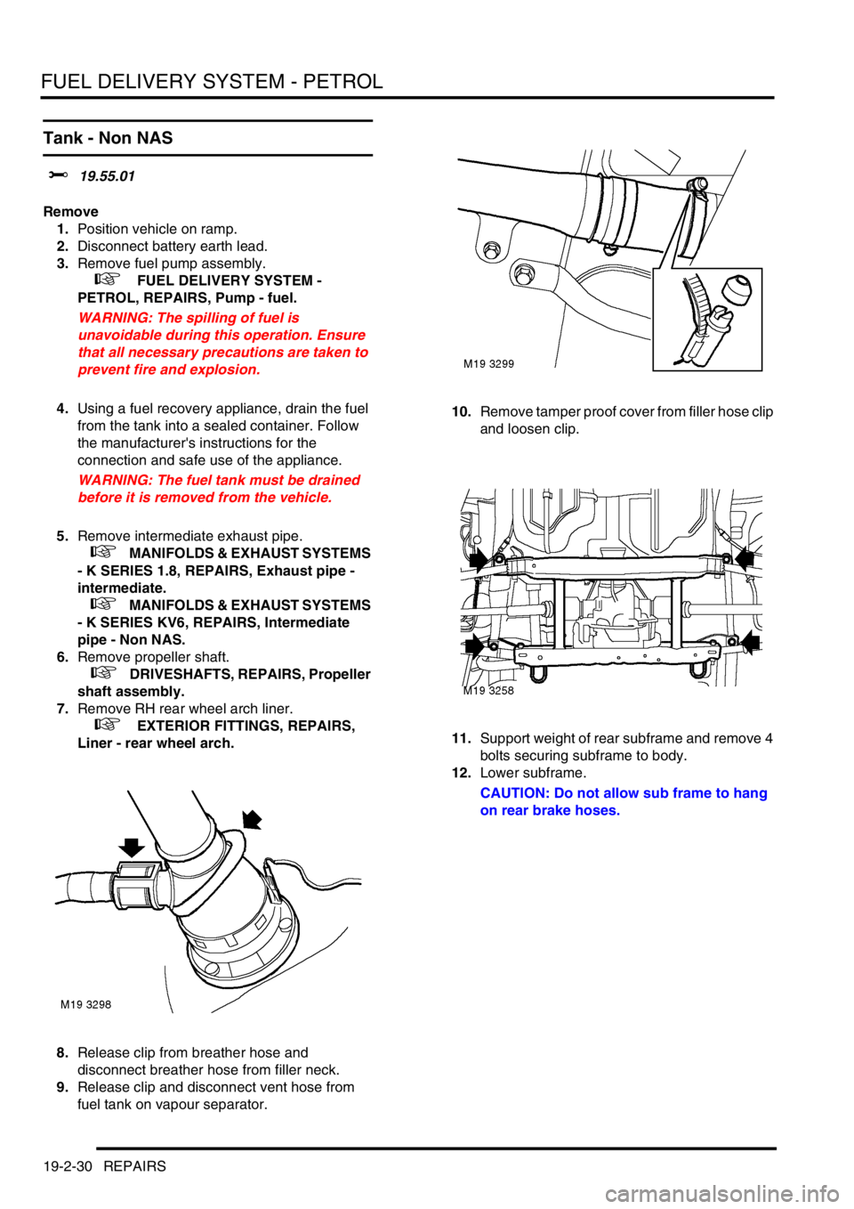
8.Release clip from breather hose and
disconnect breather hose from filler neck.
9.Release clip and disconnect vent hose from
fuel tank on vapour separator.10.Remove tamper proof cover from filler hose clip
and loosen clip.
11.Support weight of rear subframe and remove 4
bolts securing subframe to body.
12.Lower subframe.
CAUTION: Do not allow sub frame to hang
on rear brake hoses.
Page 352 of 1007
FUEL DELIVERY SYSTEM - PETROL
REPAIRS 19-2-31
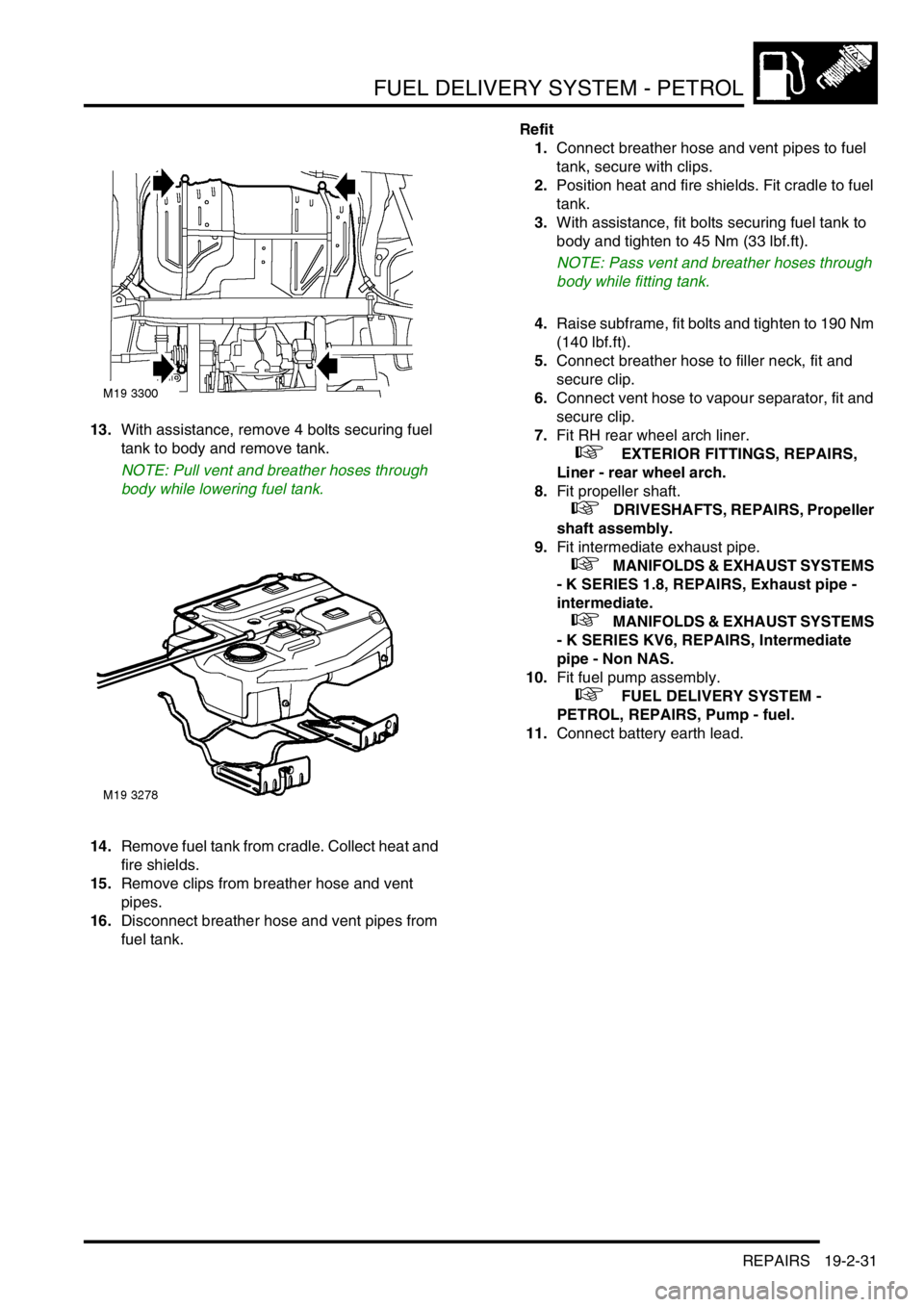
13.With assistance, remove 4 bolts securing fuel
tank to body and remove tank.
NOTE: Pull vent and breather hoses through
body while lowering fuel tank.
14.Remove fuel tank from cradle. Collect heat and
fire shields.
15.Remove clips from breather hose and vent
pipes.
16.Disconnect breather hose and vent pipes from
fuel tank.Refit
1.Connect breather hose and vent pipes to fuel
tank, secure with clips.
2.Position heat and fire shields. Fit cradle to fuel
tank.
3.With assistance, fit bolts securing fuel tank to
body and tighten to 45 Nm (33 lbf.ft).
NOTE: Pass vent and breather hoses through
body while fitting tank.
4.Raise subframe, fit bolts and tighten to 190 Nm
(140 lbf.ft).
5.Connect breather hose to filler neck, fit and
secure clip.
6.Connect vent hose to vapour separator, fit and
secure clip.
7.Fit RH rear wheel arch liner.
+ EXTERIOR FITTINGS, REPAIRS,
Liner - rear wheel arch.
8.Fit propeller shaft.
+ DRIVESHAFTS, REPAIRS, Propeller
shaft assembly.
9.Fit intermediate exhaust pipe.
+ MANIFOLDS & EXHAUST SYSTEMS
- K SERIES 1.8, REPAIRS, Exhaust pipe -
intermediate.
+ MANIFOLDS & EXHAUST SYSTEMS
- K SERIES KV6, REPAIRS, Intermediate
pipe - Non NAS.
10.Fit fuel pump assembly.
+ FUEL DELIVERY SYSTEM -
PETROL, REPAIRS, Pump - fuel.
11.Connect battery earth lead.
Page 353 of 1007
FUEL DELIVERY SYSTEM - PETROL
19-2-32 REPAIRS
Tank - NAS
$% 19.55.01
Remove
1.Position vehicle on ramp.
2.Disconnect battery earth lead.
3.Using a fuel recovery appliance, drain the fuel
from the tank into a sealed container. Follow
the manufacturer's instructions for the
connection and safe use of the appliance.
+ FUEL DELIVERY SYSTEM -
PETROL, ADJUSTMENTS, Fuel tank - drain.
WARNING: The fuel tank must be drained
before it is removed from the vehicle.
4.Remove intermediate exhaust pipe.
+ MANIFOLDS & EXHAUST SYSTEMS
- K SERIES KV6, REPAIRS, Intermediate
pipe - NAS.
5.Remove propeller shaft.
+ DRIVESHAFTS, REPAIRS, Propeller
shaft assembly.
6.Remove RH rear wheel arch liner.
+ EXTERIOR FITTINGS, REPAIRS,
Liner - rear wheel arch.
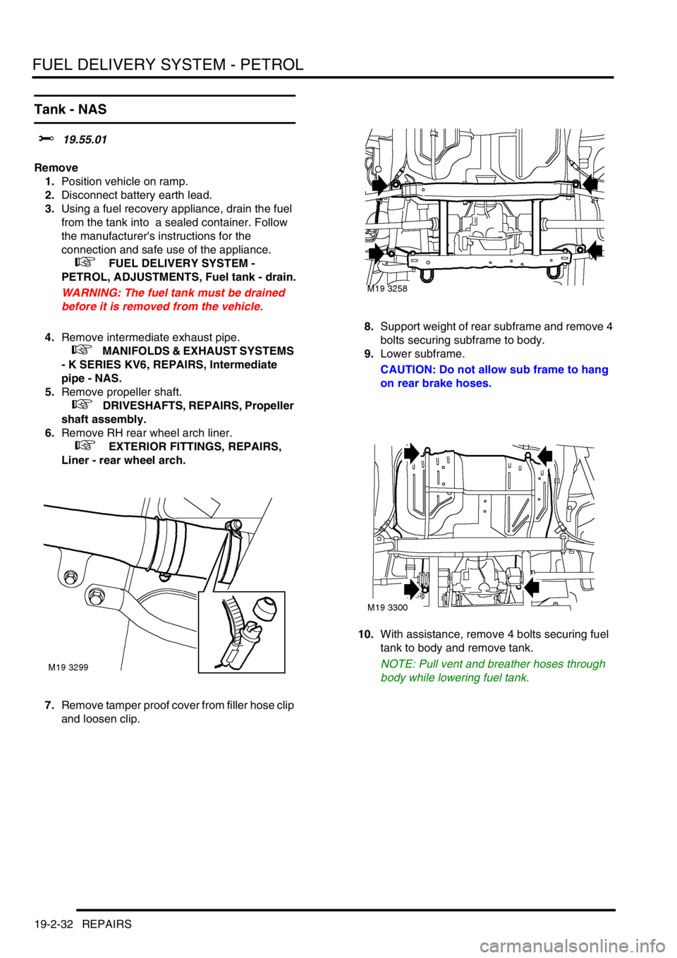
7.Remove tamper proof cover from filler hose clip
and loosen clip.8.Support weight of rear subframe and remove 4
bolts securing subframe to body.
9.Lower subframe.
CAUTION: Do not allow sub frame to hang
on rear brake hoses.
10.With assistance, remove 4 bolts securing fuel
tank to body and remove tank.
NOTE: Pull vent and breather hoses through
body while lowering fuel tank.
Page 457 of 1007

AUTOMATIC GEARBOX - JATCO
44-22 REPAIRS
42.Remove 2 top bolts securing gearbox to
engine.
43.Release gearbox from 2 dowels.
44.Manoeuvre and lower gearbox to floor.
45.Fit converter retaining plate and secure with
bolts.Refit
1.Remove torque converter retaining plate.
2.Ensure converter is fully located in oil pump
drive by checking depth 'A' as illustrated. Depth
A = 4 mm.
3.Clean gearbox to engine mating faces, dowels
and dowel holes.
4.Fit gearbox assembly.
5.Fit bolts securing gearbox and tighten to 85 Nm
(63 lbf.ft).
6.Position LH mounting bracket to gearbox, fit
and tighten bolts to 85 Nm (63 lbf.ft).
7.Position LH mounting to body, fit and tighten
bolts to 48 Nm (35 lbf.ft).
8.Align gearbox bracket to LH body mounting, fit
and tighten through bolt to 100 Nm (74 lbf.ft).
9.Disconnect lifting equipment.
10.Remove nuts and bolts securing lifting brackets
to gearbox and remove brackets.
11.Connect engine and gearbox harness
multiplugs to main harness.
12.Secure multiplugs to clips.
13.Position engine earth lead and secure with bolt.
14.Fit starter motor.
+ CHARGING AND STARTING,
REPAIRS, Starter motor - KV6.
15.Clean throttle housing and manifold chamber
mating faces.
16.Fit new seal to inlet manifold chamber.
17.Position throttle housing to manifold chamber,
fit Torx screws and tighten to 7 Nm (7 lbf.ft).
18.Connect throttle inner cable to throttle cam and
secure outer cable in abutment bracket, if fitted.
19.Connect hose to cruise control actuator.
20.Secure breather hoses to throttle housing, if
fitted.
21.Adjust throttle cable, if fitted.
+ FUEL DELIVERY SYSTEM -
PETROL, ADJUSTMENTS, Throttle cable -
check and adjust - KV6.
22.Clean CKP sensor and mating face.
M44 1689
A
M44 1668
Page 502 of 1007
STEERING
REPAIRS 57-9
Oil cooler - Td4 & K1.8 models
$% 57.15.11
Remove
1.Disconnect battery earth lead.
2.Remove engine acoustic cover if fitted.
+ ENGINE - Td4, REPAIRS, Cover -
engine acoustic - Up to 02.5 Model Year.
3. Td4 models: Release and remove air intake
duct.
+ FUEL DELIVERY SYSTEM - DIESEL,
REPAIRS, Ducting - intake assembly.
4. Td4 models: Loosen 2 clips and remove
intercooler outlet hose.
5. Td4 models: Remove dipstick for access.
CAUTION: Always fit plugs to open
connections to prevent contamination.
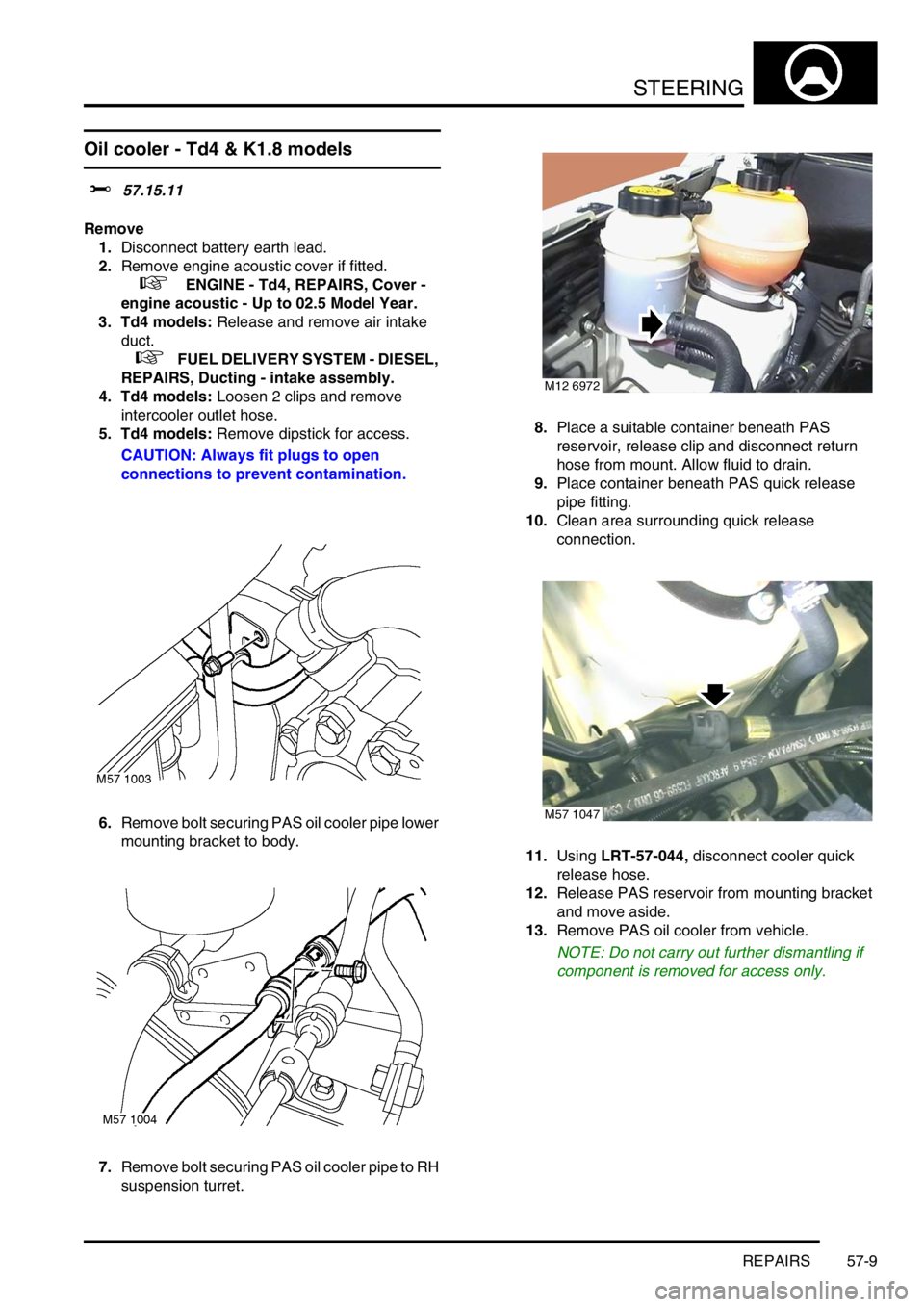
6.Remove bolt securing PAS oil cooler pipe lower
mounting bracket to body.
7.Remove bolt securing PAS oil cooler pipe to RH
suspension turret.8.Place a suitable container beneath PAS
reservoir, release clip and disconnect return
hose from mount. Allow fluid to drain.
9.Place container beneath PAS quick release
pipe fitting.
10.Clean area surrounding quick release
connection.
11.Using LRT-57-044, disconnect cooler quick
release hose.
12.Release PAS reservoir from mounting bracket
and move aside.
13.Remove PAS oil cooler from vehicle.
NOTE: Do not carry out further dismantling if
component is removed for access only.
M12 6972
M57 1047
Page 503 of 1007
STEERING
57-10 REPAIRS
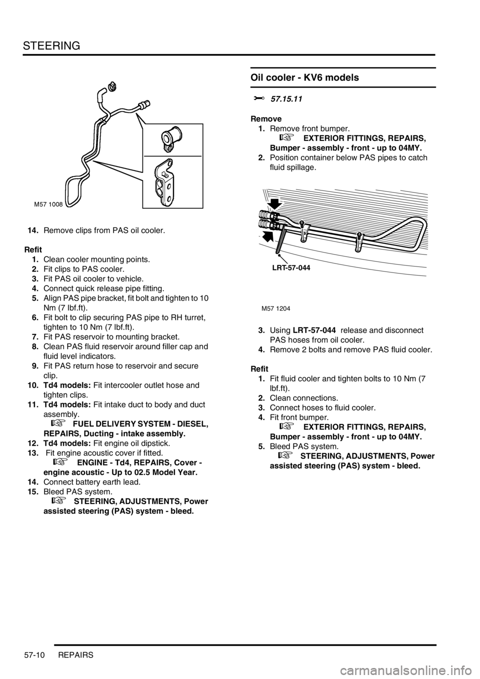
14.Remove clips from PAS oil cooler.
Refit
1.Clean cooler mounting points.
2.Fit clips to PAS cooler.
3.Fit PAS oil cooler to vehicle.
4.Connect quick release pipe fitting.
5.Align PAS pipe bracket, fit bolt and tighten to 10
Nm (7 lbf.ft).
6.Fit bolt to clip securing PAS pipe to RH turret,
tighten to 10 Nm (7 lbf.ft).
7.Fit PAS reservoir to mounting bracket.
8.Clean PAS fluid reservoir around filler cap and
fluid level indicators.
9.Fit PAS return hose to reservoir and secure
clip.
10. Td4 models: Fit intercooler outlet hose and
tighten clips.
11. Td4 models: Fit intake duct to body and duct
assembly.
+ FUEL DELIVERY SYSTEM - DIESEL,
REPAIRS, Ducting - intake assembly.
12. Td4 models: Fit engine oil dipstick.
13. Fit engine acoustic cover if fitted.
+ ENGINE - Td4, REPAIRS, Cover -
engine acoustic - Up to 02.5 Model Year.
14.Connect battery earth lead.
15.Bleed PAS system.
+ STEERING, ADJUSTMENTS, Power
assisted steering (PAS) system - bleed.
Oil cooler - KV6 models
$% 57.15.11
Remove
1.Remove front bumper.
+ EXTERIOR FITTINGS, REPAIRS,
Bumper - assembly - front - up to 04MY.
2.Position container below PAS pipes to catch
fluid spillage.
3.Using LRT-57-044 release and disconnect
PAS hoses from oil cooler.
4.Remove 2 bolts and remove PAS fluid cooler.
Refit
1.Fit fluid cooler and tighten bolts to 10 Nm (7
lbf.ft).
2.Clean connections.
3.Connect hoses to fluid cooler.
4.Fit front bumper.
+ EXTERIOR FITTINGS, REPAIRS,
Bumper - assembly - front - up to 04MY.
5.Bleed PAS system.
+ STEERING, ADJUSTMENTS, Power
assisted steering (PAS) system - bleed.
M57 1204
LRT-57-044