LAND ROVER FREELANDER 2001 Workshop Manual
Manufacturer: LAND ROVER, Model Year: 2001, Model line: FREELANDER, Model: LAND ROVER FREELANDER 2001Pages: 1007, PDF Size: 23.47 MB
Page 501 of 1007
STEERING
57-8 REPAIRS
Gaiter - PAS rack
$% 57.10.29
Remove
1.Remove PAS rack.
+ STEERING, REPAIRS, Power
steering rack.
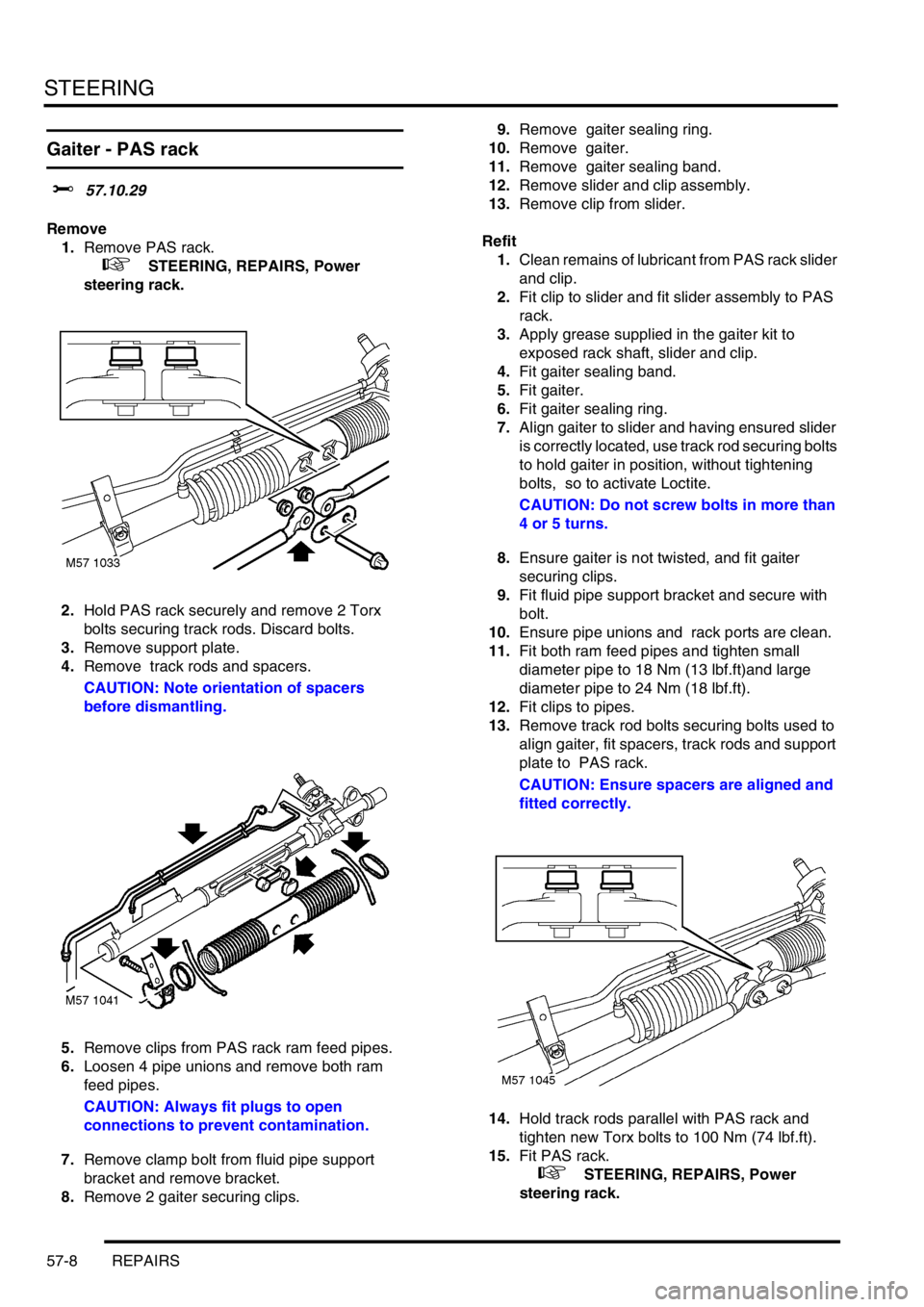
2.Hold PAS rack securely and remove 2 Torx
bolts securing track rods. Discard bolts.
3.Remove support plate.
4.Remove track rods and spacers.
CAUTION: Note orientation of spacers
before dismantling.
5.Remove clips from PAS rack ram feed pipes.
6.Loosen 4 pipe unions and remove both ram
feed pipes.
CAUTION: Always fit plugs to open
connections to prevent contamination.
7.Remove clamp bolt from fluid pipe support
bracket and remove bracket.
8.Remove 2 gaiter securing clips.9.Remove gaiter sealing ring.
10.Remove gaiter.
11.Remove gaiter sealing band.
12.Remove slider and clip assembly.
13.Remove clip from slider.
Refit
1.Clean remains of lubricant from PAS rack slider
and clip.
2.Fit clip to slider and fit slider assembly to PAS
rack.
3.Apply grease supplied in the gaiter kit to
exposed rack shaft, slider and clip.
4.Fit gaiter sealing band.
5.Fit gaiter.
6.Fit gaiter sealing ring.
7.Align gaiter to slider and having ensured slider
is correctly located, use track rod securing bolts
to hold gaiter in position, without tightening
bolts, so to activate Loctite.
CAUTION: Do not screw bolts in more than
4 or 5 turns.
8.Ensure gaiter is not twisted, and fit gaiter
securing clips.
9.Fit fluid pipe support bracket and secure with
bolt.
10.Ensure pipe unions and rack ports are clean.
11.Fit both ram feed pipes and tighten small
diameter pipe to 18 Nm (13 lbf.ft)and large
diameter pipe to 24 Nm (18 lbf.ft).
12.Fit clips to pipes.
13.Remove track rod bolts securing bolts used to
align gaiter, fit spacers, track rods and support
plate to PAS rack.
CAUTION: Ensure spacers are aligned and
fitted correctly.
14.Hold track rods parallel with PAS rack and
tighten new Torx bolts to 100 Nm (74 lbf.ft).
15.Fit PAS rack.
+ STEERING, REPAIRS, Power
steering rack.
Page 502 of 1007
STEERING
REPAIRS 57-9
Oil cooler - Td4 & K1.8 models
$% 57.15.11
Remove
1.Disconnect battery earth lead.
2.Remove engine acoustic cover if fitted.
+ ENGINE - Td4, REPAIRS, Cover -
engine acoustic - Up to 02.5 Model Year.
3. Td4 models: Release and remove air intake
duct.
+ FUEL DELIVERY SYSTEM - DIESEL,
REPAIRS, Ducting - intake assembly.
4. Td4 models: Loosen 2 clips and remove
intercooler outlet hose.
5. Td4 models: Remove dipstick for access.
CAUTION: Always fit plugs to open
connections to prevent contamination.
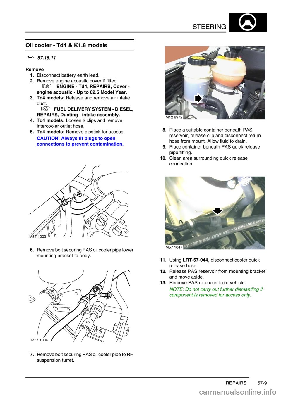
6.Remove bolt securing PAS oil cooler pipe lower
mounting bracket to body.
7.Remove bolt securing PAS oil cooler pipe to RH
suspension turret.8.Place a suitable container beneath PAS
reservoir, release clip and disconnect return
hose from mount. Allow fluid to drain.
9.Place container beneath PAS quick release
pipe fitting.
10.Clean area surrounding quick release
connection.
11.Using LRT-57-044, disconnect cooler quick
release hose.
12.Release PAS reservoir from mounting bracket
and move aside.
13.Remove PAS oil cooler from vehicle.
NOTE: Do not carry out further dismantling if
component is removed for access only.
M12 6972
M57 1047
Page 503 of 1007
STEERING
57-10 REPAIRS
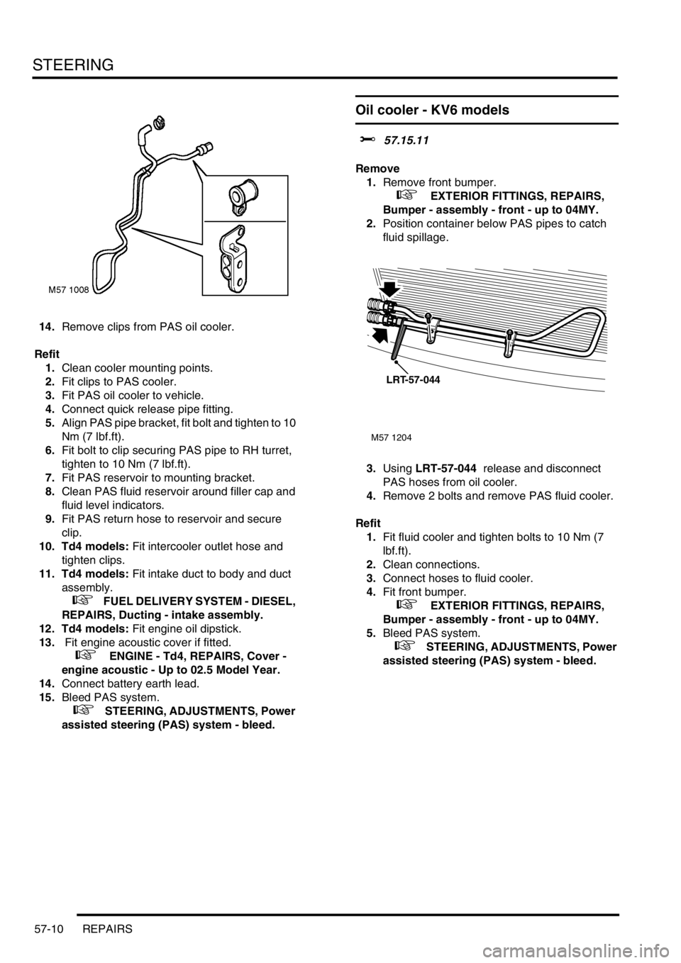
14.Remove clips from PAS oil cooler.
Refit
1.Clean cooler mounting points.
2.Fit clips to PAS cooler.
3.Fit PAS oil cooler to vehicle.
4.Connect quick release pipe fitting.
5.Align PAS pipe bracket, fit bolt and tighten to 10
Nm (7 lbf.ft).
6.Fit bolt to clip securing PAS pipe to RH turret,
tighten to 10 Nm (7 lbf.ft).
7.Fit PAS reservoir to mounting bracket.
8.Clean PAS fluid reservoir around filler cap and
fluid level indicators.
9.Fit PAS return hose to reservoir and secure
clip.
10. Td4 models: Fit intercooler outlet hose and
tighten clips.
11. Td4 models: Fit intake duct to body and duct
assembly.
+ FUEL DELIVERY SYSTEM - DIESEL,
REPAIRS, Ducting - intake assembly.
12. Td4 models: Fit engine oil dipstick.
13. Fit engine acoustic cover if fitted.
+ ENGINE - Td4, REPAIRS, Cover -
engine acoustic - Up to 02.5 Model Year.
14.Connect battery earth lead.
15.Bleed PAS system.
+ STEERING, ADJUSTMENTS, Power
assisted steering (PAS) system - bleed.
Oil cooler - KV6 models
$% 57.15.11
Remove
1.Remove front bumper.
+ EXTERIOR FITTINGS, REPAIRS,
Bumper - assembly - front - up to 04MY.
2.Position container below PAS pipes to catch
fluid spillage.
3.Using LRT-57-044 release and disconnect
PAS hoses from oil cooler.
4.Remove 2 bolts and remove PAS fluid cooler.
Refit
1.Fit fluid cooler and tighten bolts to 10 Nm (7
lbf.ft).
2.Clean connections.
3.Connect hoses to fluid cooler.
4.Fit front bumper.
+ EXTERIOR FITTINGS, REPAIRS,
Bumper - assembly - front - up to 04MY.
5.Bleed PAS system.
+ STEERING, ADJUSTMENTS, Power
assisted steering (PAS) system - bleed.
M57 1204
LRT-57-044
Page 504 of 1007
STEERING
REPAIRS 57-11
Drive belt - K1.8
$% 57.20.02
Remove
1.Disconnect battery earth lead.
2.Turn steering on RH lock.
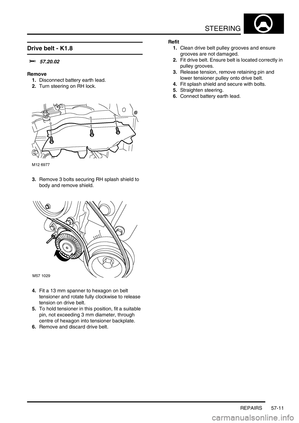
3.Remove 3 bolts securing RH splash shield to
body and remove shield.
4.Fit a 13 mm spanner to hexagon on belt
tensioner and rotate fully clockwise to release
tension on drive belt.
5.To hold tensioner in this position, fit a suitable
pin, not exceeding 3 mm diameter, through
centre of hexagon into tensioner backplate.
6.Remove and discard drive belt.Refit
1.Clean drive belt pulley grooves and ensure
grooves are not damaged.
2.Fit drive belt. Ensure belt is located correctly in
pulley grooves.
3.Release tension, remove retaining pin and
lower tensioner pulley onto drive belt.
4.Fit splash shield and secure with bolts.
5.Straighten steering.
6.Connect battery earth lead.
Page 505 of 1007
STEERING
57-12 REPAIRS
Pump - steering - KV6
$% 57.20.14
Remove
1.Disconnect battery earth lead.
2.Remove engine mounting top arm.
+ ENGINE - K SERIES KV6, REPAIRS,
Arm assembly - engine mounting RH.
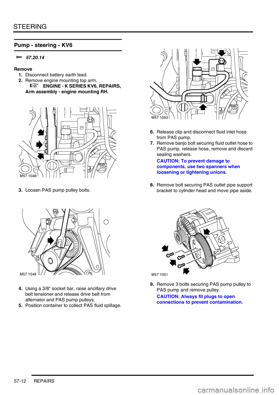
3.Loosen PAS pump pulley bolts.
4.Using a 3/8" socket bar, raise ancillary drive
belt tensioner and release drive belt from
alternator and PAS pump pulleys.
5.Position container to collect PAS fluid spillage.6.Release clip and disconnect fluid inlet hose
from PAS pump.
7.Remove banjo bolt securing fluid outlet hose to
PAS pump, release hose, remove and discard
sealing washers.
CAUTION: To prevent damage to
components, use two spanners when
loosening or tightening unions.
8.Remove bolt securing PAS outlet pipe support
bracket to cylinder head and move pipe aside.
9.Remove 3 bolts securing PAS pump pulley to
PAS pump and remove pulley.
CAUTION: Always fit plugs to open
connections to prevent contamination.
Page 506 of 1007
STEERING
REPAIRS 57-13
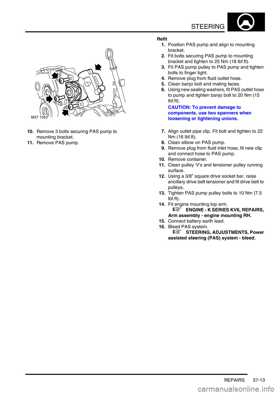
10.Remove 3 bolts securing PAS pump to
mounting bracket.
11.Remove PAS pump.Refit
1.Position PAS pump and align to mounting
bracket.
2.Fit bolts securing PAS pump to mounting
bracket and tighten to 25 Nm (18 lbf.ft).
3.Fit PAS pump pulley to PAS pump and tighten
bolts to finger tight.
4.Remove plug from fluid outlet hose.
5.Clean banjo bolt and mating faces.
6.Using new sealing washers, fit PAS outlet hose
to pump and tighten banjo bolt to 20 Nm (15
lbf.ft).
CAUTION: To prevent damage to
components, use two spanners when
loosening or tightening unions.
7.Align outlet pipe clip. Fit bolt and tighten to 22
Nm (16 lbf.ft).
8.Clean elbow on PAS pump.
9.Remove plug from fluid inlet hose, fit new clip
and connect hose to PAS pump.
10.Remove container.
11.Clean pulley 'V's and tensioner pulley running
surface.
12.Using a 3/8” square drive socket bar, raise
ancillary drive belt tensioner and fit drive belt to
pulleys.
13.Tighten PAS pump pulley bolts to 10 Nm (7.5
lbf.ft).
14.Fit engine mounting top arm.
+ ENGINE - K SERIES KV6, REPAIRS,
Arm assembly - engine mounting RH.
15.Connect battery earth lead.
16.Bleed PAS system.
+ STEERING, ADJUSTMENTS, Power
assisted steering (PAS) system - bleed.
Page 507 of 1007
STEERING
57-14 REPAIRS
Pump - steering - K1.8
$% 57.20.14
Remove
1.Disconnect battery earth lead.
2.Raise front of vehicle.
WARNING: Do not work on or under a
vehicle supported only by a jack. Always
support the vehicle on safety stands.
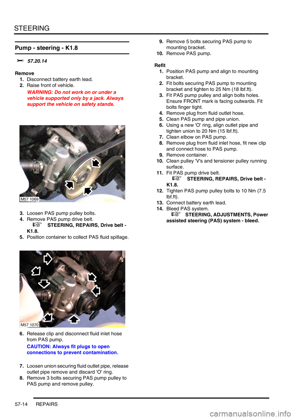
3.Loosen PAS pump pulley bolts.
4.Remove PAS pump drive belt.
+ STEERING, REPAIRS, Drive belt -
K1.8.
5.Position container to collect PAS fluid spillage.
6.Release clip and disconnect fluid inlet hose
from PAS pump.
CAUTION: Always fit plugs to open
connections to prevent contamination.
7.Loosen union securing fluid outlet pipe, release
outlet pipe remove and discard 'O' ring.
8.Remove 3 bolts securing PAS pump pulley to
PAS pump and remove pulley.9.Remove 5 bolts securing PAS pump to
mounting bracket.
10.Remove PAS pump.
Refit
1.Position PAS pump and align to mounting
bracket.
2.Fit bolts securing PAS pump to mounting
bracket and tighten to 25 Nm (18 lbf.ft).
3.Fit PAS pump pulley and align bolts holes.
Ensure FRONT mark is facing outwards. Fit
bolts finger tight.
4.Remove plug from fluid outlet hose.
5.Clean PAS pump and pipe union.
6.Using a new 'O' ring, align outlet pipe and
tighten union to 20 Nm (15 lbf.ft).
7.Clean elbow on PAS pump.
8.Remove plug from fluid inlet hose, fit new clip
and connect hose to PAS pump.
9.Remove container.
10.Clean pulley 'V's and tensioner pulley running
surface.
11.Fit PAS pump drive belt.
+ STEERING, REPAIRS, Drive belt -
K1.8.
12.Tighten PAS pump pulley bolts to 10 Nm (7.5
lbf.ft).
13.Connect battery earth lead.
14.Bleed PAS system.
+ STEERING, ADJUSTMENTS, Power
assisted steering (PAS) system - bleed.
M57 1069
M57 1070
Page 508 of 1007
STEERING
REPAIRS 57-15
Pump - steering - Td4
$% 57.20.14
Remove
1.Disconnect battery earth lead.
2.Remove hydramount.
+ ENGINE - Td4, REPAIRS,
Hydramount - engine - RH.
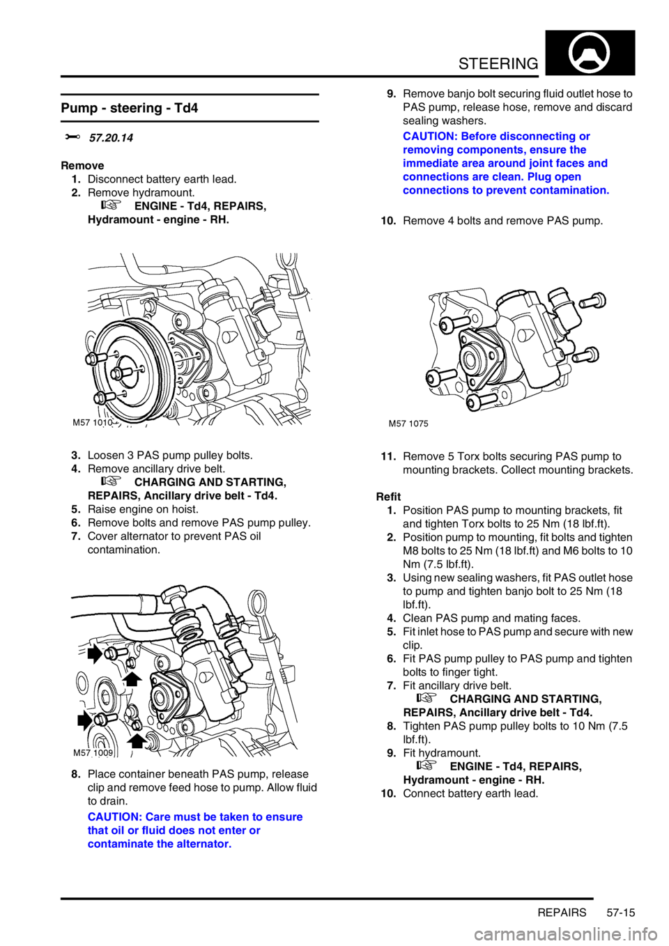
3.Loosen 3 PAS pump pulley bolts.
4.Remove ancillary drive belt.
+ CHARGING AND STARTING,
REPAIRS, Ancillary drive belt - Td4.
5.Raise engine on hoist.
6.Remove bolts and remove PAS pump pulley.
7.Cover alternator to prevent PAS oil
contamination.
8.Place container beneath PAS pump, release
clip and remove feed hose to pump. Allow fluid
to drain.
CAUTION: Care must be taken to ensure
that oil or fluid does not enter or
contaminate the alternator.9.Remove banjo bolt securing fluid outlet hose to
PAS pump, release hose, remove and discard
sealing washers.
CAUTION: Before disconnecting or
removing components, ensure the
immediate area around joint faces and
connections are clean. Plug open
connections to prevent contamination.
10.Remove 4 bolts and remove PAS pump.
11.Remove 5 Torx bolts securing PAS pump to
mounting brackets. Collect mounting brackets.
Refit
1.Position PAS pump to mounting brackets, fit
and tighten Torx bolts to 25 Nm (18 lbf.ft).
2.Position pump to mounting, fit bolts and tighten
M8 bolts to 25 Nm (18 lbf.ft) and M6 bolts to 10
Nm (7.5 lbf.ft).
3.Using new sealing washers, fit PAS outlet hose
to pump and tighten banjo bolt to 25 Nm (18
lbf.ft).
4.Clean PAS pump and mating faces.
5.Fit inlet hose to PAS pump and secure with new
clip.
6.Fit PAS pump pulley to PAS pump and tighten
bolts to finger tight.
7.Fit ancillary drive belt.
+ CHARGING AND STARTING,
REPAIRS, Ancillary drive belt - Td4.
8.Tighten PAS pump pulley bolts to 10 Nm (7.5
lbf.ft).
9.Fit hydramount.
+ ENGINE - Td4, REPAIRS,
Hydramount - engine - RH.
10.Connect battery earth lead.
Page 509 of 1007
STEERING
57-16 REPAIRS
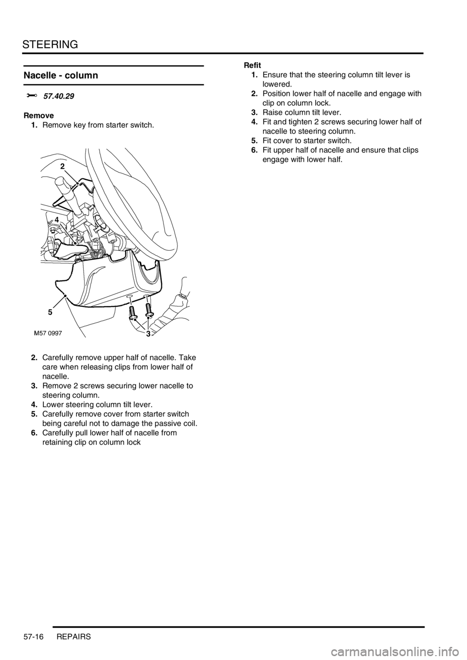
Nacelle - column
$% 57.40.29
Remove
1.Remove key from starter switch.
2.Carefully remove upper half of nacelle. Take
care when releasing clips from lower half of
nacelle.
3.Remove 2 screws securing lower nacelle to
steering column.
4.Lower steering column tilt lever.
5.Carefully remove cover from starter switch
being careful not to damage the passive coil.
6.Carefully pull lower half of nacelle from
retaining clip on column lockRefit
1.Ensure that the steering column tilt lever is
lowered.
2.Position lower half of nacelle and engage with
clip on column lock.
3.Raise column tilt lever.
4.Fit and tighten 2 screws securing lower half of
nacelle to steering column.
5.Fit cover to starter switch.
6.Fit upper half of nacelle and ensure that clips
engage with lower half.
Page 510 of 1007
STEERING
REPAIRS 57-17
Column lock & ignition/starter switch
assembly
$% 57.40.31
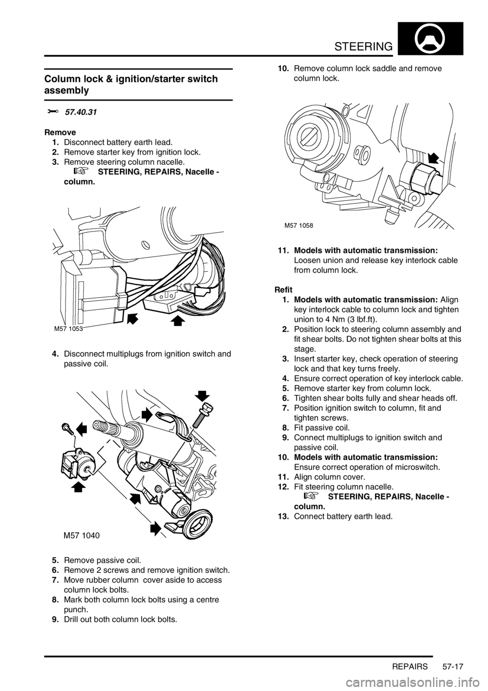
Remove
1.Disconnect battery earth lead.
2.Remove starter key from ignition lock.
3.Remove steering column nacelle.
+ STEERING, REPAIRS, Nacelle -
column.
4.Disconnect multiplugs from ignition switch and
passive coil.
5.Remove passive coil.
6.Remove 2 screws and remove ignition switch.
7.Move rubber column cover aside to access
column lock bolts.
8.Mark both column lock bolts using a centre
punch.
9.Drill out both column lock bolts.10.Remove column lock saddle and remove
column lock.
11. Models with automatic transmission:
Loosen union and release key interlock cable
from column lock.
Refit
1. Models with automatic transmission: Align
key interlock cable to column lock and tighten
union to 4 Nm (3 lbf.ft).
2.Position lock to steering column assembly and
fit shear bolts. Do not tighten shear bolts at this
stage.
3.Insert starter key, check operation of steering
lock and that key turns freely.
4.Ensure correct operation of key interlock cable.
5.Remove starter key from column lock.
6.Tighten shear bolts fully and shear heads off.
7.Position ignition switch to column, fit and
tighten screws.
8.Fit passive coil.
9.Connect multiplugs to ignition switch and
passive coil.
10. Models with automatic transmission:
Ensure correct operation of microswitch.
11.Align column cover.
12.Fit steering column nacelle.
+ STEERING, REPAIRS, Nacelle -
column.
13.Connect battery earth lead.