brake light LAND ROVER FREELANDER 2001 Workshop Manual
[x] Cancel search | Manufacturer: LAND ROVER, Model Year: 2001, Model line: FREELANDER, Model: LAND ROVER FREELANDER 2001Pages: 1007, PDF Size: 23.47 MB
Page 14 of 1007

CONTENTS
CONTENTS 11
REAR SUSPENSION ................................................................................ 64-1
REPAIRS
Bush - trailing link............................................................................................................................ 64-1
Bearing - hub ................................................................................................................................. 64-2
Damper .......................................................................................................................................... 64-5
Trailing arm .................................................................................................................................... 64-8
Bush - trailing arm .......................................................................................................................... 64-9
Link - adjustable - transverse ......................................................................................................... 64-10
Link - transverse fixed .................................................................................................................... 64-11
Bush - link - transverse .................................................................................................................. 64-12
Sub frame ...................................................................................................................................... 64-13
BRAKES ................................................................................................... 70-1
ADJUSTMENTS
Brake bleed ..................................................................................................................................... 70-1
Cable - handbrake - check and adjust ............................................................................................ 70-2
REPAIRS
Drum - rear ...................................................................................................................................... 70-3
Disc - front....................................................................................................................................... 70-5
Hose - front - primary - LH .............................................................................................................. 70-6
Hose - rear ...................................................................................................................................... 70-7
Cylinder - master - tandem - LHD ................................................................................................... 70-8
Cylinder - master - tandem - RHD................................................................................................... 70-9
Lever assembly - handbrake........................................................................................................... 70-10
Cable - handbrake ......................................................................................................................... 70-11
Switch - handbrake warning ............................................................................................................ 70-12
Switch - stop light ............................................................................................................................ 70-13
Sensor - brake pedal position ........................................................................................................ 70-13
Shoes/pads - front - set................................................................................................................... 70-14
Brake Shoes - rear set .................................................................................................................... 70-15
Servo assembly - LHD .................................................................................................................... 70-17
Servo assembly - RHD ................................................................................................................... 70-19
Vacuum pump - Td4 - manual ........................................................................................................ 70-20
Vacuum pump - Td4 - automatic ..................................................................................................... 70-21
Vacuum - enhancer - KV6 .............................................................................................................. 70-22
Carrier assembly - calliper - front ................................................................................................... 70-23
Wheel cylinder - rear ....................................................................................................................... 70-24
Switch - low fluid level ..................................................................................................................... 70-25
Sensor & harness - front wheel - RH .............................................................................................. 70-25
Sensor & harness - front wheel - LH ............................................................................................... 70-27
Sensor & harness - rear wheel ....................................................................................................... 70-29
Modulator unit ................................................................................................................................. 70-30
Switch - hill descent - from 04MY ................................................................................................... 70-31
Switch - hill descent - up to 03MY................................................................................................... 70-32
Page 24 of 1007

CONTENTS
CONTENTS 21
WINDOWS ................................................................................................ 86-5-1
REPAIRS
Motor & control unit - front door - 3 door ......................................................................................... 86-5-1
Motor & control unit - front door - 5 door ......................................................................................... 86-5-2
Switch - master window - 5 door - from 04MY ................................................................................ 86-5-2
Relay - control - tail door glass ....................................................................................................... 86-5-3
Microswitch - hardtop sensing - 3 door ........................................................................................... 86-5-4
Relay - heated front screen ........................................................................................................... 86-5-5
Switch - backlight heater ................................................................................................................. 86-5-6
IN CAR ENTERTAINMENT ...................................................................... 86-6-1
REPAIRS
Radio - up to 04MY ......................................................................................................................... 86-6-1
Radio/CD - from 04MY .................................................................................................................... 86-6-2
Speaker - rear - 3 door .................................................................................................................... 86-6-3
Speaker - rear - 5 door .................................................................................................................... 86-6-3
Speaker - front ................................................................................................................................ 86-6-4
Aerial - manual - 3 door .................................................................................................................. 86-6-4
Aerial - manual - 5 door .................................................................................................................. 86-6-5
Coaxial lead - front aerial - 3 door ................................................................................................... 86-6-6
Coaxial lead - front aerial - 5 door ................................................................................................... 86-6-7
Speaker - tweeter - front ................................................................................................................. 86-6-8
Speaker - tweeter - rear - 3 door ..................................................................................................... 86-6-9
Amplifier - power ............................................................................................................................ 86-6-10
Sub-woofer assembly .................................................................................................................... 86-6-11
Coaxial lead - extension.................................................................................................................. 86-6-12
HARNESSES ............................................................................................ 86-7-1
REPAIRS
Fuse box - passenger compartment ............................................................................................... 86-7-1
Harness - main ................................................................................................................................ 86-7-2
Harness - tailgate ............................................................................................................................ 86-7-12
Harness - interior lights - 5 door ...................................................................................................... 86-7-15
Harness - front door - 5 door ........................................................................................................... 86-7-15
Harness - rear door ......................................................................................................................... 86-7-16
DRIVER CONTROLS ................................................................................ 86-8-1
REPAIRS
Switch - remote control - audio system .......................................................................................... 86-8-1
Switch - park distance control (PDC) - from 04 MY ........................................................................ 86-8-1
Control unit (ECU) - parking aid - from 04MY ................................................................................. 86-8-2
Sensor - parking aid - rear - from 04MY ......................................................................................... 86-8-2
Sounder - parking aid - rear - from 04MY ....................................................................................... 86-8-3
Switch - handbrake warning ............................................................................................................ 86-8-3
Switch - hazard warning - from 04MY ............................................................................................. 86-8-4
Cigar lighter - front .......................................................................................................................... 86-8-4
Switch - control - exterior mirror ...................................................................................................... 86-8-5
Page 29 of 1007

INTRODUCTION
01-4
HRW Heated Rear Window
ht/HT High tension
HSLA High Strength Low Alloy
IACV Idle Air Control Valve
IAT Intake Air Temperature
ICE In-Car Entertainment
i.dia. Internal diameter
IDM Intelligent Driver Module
IF Intermediate Frequency
in Inch
in
2Square inch
in3Cubic inch
ILT Inlet Throttle
ISO International Organisation for
Standardisation
ITS Inflatable Tubular Structure
k Thousand
kg Kilogramme
kg/h Kilogrammes per hour
km Kilometre
km/h Kilometres per hour
kPa KiloPascal
KS Knock Sensor
lb(s) Pounds
lbf Pounds force
lbf.in Pounds force inches
lbf/in
2Pounds per square inch
lbf.ft Pounds force feet
λLambda
lc Low compression
LCD Liquid Crystal Display
LED Light Emitting Diode
LEV Low Emission Vehicle
LH Left-Hand
LHD Left-Hand Drive
LSM Light Switch Module
LVS Liquid Vapour Separator
mMetre
µMicro
MAF Mass Air Flow
MAP Manifold Absolute Pressure
MFU Multi-Function Unit
MFL Multi-Function Logic
max. Maximum
MEMS Modular Engine Management
System
MIG Metal/Inert Gas
MIL Malfunction Indicator Lamp
MPa MegaPascal
MOSFET Metal Oxide Semiconductor Field
Effect Transistor
min. Minimum
- Minus (tolerance)
' Minute (angle)
mm Millimetre
mph Miles per hour MPi Multi-Point injection
MV Motorised Valve
MY Model Year
NAS North American Specification
(-) Negative (electrical)
Nm Newton metre
No. Number
NO
2Nitrogen Dioxide
NO
xOxides of Nitrogen
NTC Negative Temperature
Coefficient
NRV Non Return Valve
OBD On Board Diagnostics
OBM On Board Monitoring
o.dia. Outside diameter
OAT Organic Acid Technology
ORM Off-road Mode
ΩOhm
PAS Power Assisted Steering
PCB Printed Circuit Board
PCV Positive Crankcase Ventilation
PDC Parking Distance Control
PDOP Position Dilation Of Precision
PI Programme Information
PPS Pulse Per Second
PS Programme Service
psi Pounds per square inch
pts. Pints
% Percentage
+ Plus (tolerance) or Positive
(electrical)
±Plus or minus (tolerance)
PTC Positive Temperature Coefficient
PTFE Polytetrafluorethylene
PWM Pulse Width Modulation
RDS Radio Data Service
rRadius
:Ratio
ref Reference
REG Regionalisation
RES Rover Engineering Standards
rev/min Revolutions per minute
RF Radio Frequency
RGB Red / Green / Blue
RH Right-Hand
RHD Right-Hand Drive
ROM Read Only Memory
RON Research Octane Number
ROV Roll Over Valve
ROW Rest Of World
SAE Society of Automotive Engineers
SAI Secondary Air Injection
" Second (angle)
SLABS Self Levelling and Anti-Lock
Brake System
SLS Self Levelling Suspension
SOHC Single Overhead Camshaft
SPE Single Point Entry
Page 38 of 1007

GENERAL INFORMATION
03-7
General fitting instructions
Precautions against damage
To avoid damage to the vehicle when carrying out
repairs, always adhere to the following:
lAlways fit wing and seat covers before
commencing work. Avoid spilling brake fluid or
battery acid on paintwork; immediately wash off
with water if this occurs.
lDisconnect the battery earth lead before starting
work, see ELECTRICAL PRECAUTIONS.
lAlways use the recommended service tool or a
satisfactory equivalent where specified.
lProtect exposed bearing surfaces, sealing
surfaces and screw threads from damage.
Component removal
Whenever possible, clean components and
surrounding area before removal.
lBlank off openings exposed by component
removal.
lImmediately seal fuel, oil or hydraulic lines when
apertures are exposed; use plastic caps or
plugs to prevent loss of fluid and ingress of dirt.
lClose open ends of oilways exposed by
component removal with tapered hardwood
plugs or conspicuous plastic plugs.
lImmediately a component is removed, place it in
a suitable container; use a separate container
for each component and its associated parts.
lClean bench and provide marking materials,
labels, containers and locking wire before
dismantling a component.
Dismantling
Observe scrupulous cleanliness when dismantling
components, particularly when brake, fuel or
hydraulic system parts are being worked on. A
particle of dirt or a cloth fragment could cause a
serious malfunction if trapped in these systems.Use the following procedures:
lBlow out all tapped holes, crevices, oilways and
fluid passages with an air line. Ensure that any
O-rings used for sealing are correctly replaced
or renewed if disturbed during the process.
lUse marking ink to identify mating parts and
ensure correct reassembly. Do not use a centre
punch or scriber to mark parts, they could
initiate cracks or distortion in marked
components.
lWire together mating parts where necessary to
prevent accidental interchange (e.g. roller
bearing components).
lWire labels on to all parts which are to be
renewed, and to parts requiring further
inspection before being passed for reassembly;
place these parts in separate containers from
those containing parts for rebuild.
lDo not discard a part due for renewal until after
comparing it with a new part to ensure that its
correct replacement has been obtained.
Cleaning components
Always use the recommended cleaning agent or
equivalent. Ensure that adequate ventilation is
provided when volatile degreasing agents are being
used. Do not use degreasing equipment for
components containing items which could be
damaged by the use of this process.
When washing under bonnet, never direct water onto
ECM, as water ingress may occur resulting in
damage to electrical components inside.
General Inspection
All components should be inspected for wear or
damage before being reassembled.
lNever inspect a component for wear or
dimensional check unless it is absolutely clean;
a slight smear of grease can conceal an
incipient failure.
lWhen a component is to be checked
dimensionally against recommended values,
use the appropriate measuring equipment
(surface plates, micrometers, dial gauges etc.).
Ensure the measuring equipment is calibrated
and in good serviceable condition.
lReject a component if its dimensions are
outside the specified tolerances, or if it appears
to be damaged.
lA part may be refitted if its critical dimension is
exactly to its tolerance limit and it appears to be
in satisfactory condition.
lUse 'Plastigauge' 12 Type PG-1 for checking
bearing surface clearances.
Page 48 of 1007
GENERAL INFORMATION
03-17
SPX Corporation,
665, Eisenhower Drive,
Owatonna,
MN 55060,
USA
( 0018 772979110
) 0018 005787375
Australia
SPX Australia,
28, Clayton Road,
Notting Hill,
Victoria 3168,
Australia
( 00 (61) 00395446222
) 00 (61) 0395445222
e-mail: [email protected]
Japan and East Asia
Jatek Ltd.,
5 - 53, Minawacho 2-chome,
Kohoku-ku,
Yokohama,
Kanagawa 223-0051,
Japan
( 0081 455627700
) 0081 455627800
Rolling road testing
General
IMPORTANT: Use a four wheel rolling road for
brake testing if possible.
The front and rear wheels cannot be driven
independently due to the viscous coupling. This
eliminates the need for differential lock by
progressively applying more torque to the rear
wheels if the front wheels start to slip.
DO NOT attempt to drive individual wheels with
vehicle supported on floor jacks or stands.
Four wheel rolling road
Provided that front and rear rollers are rotating at
identical speeds and that normal workshop safety
standards are applied, there is no speed restriction
during testing, except any that may apply to the tyres.
Before testing a vehicle with anti-lock brakes on a
four wheel rolling road, disconnect the ABS
modulator. The ABS function will not work, the ABS
warning light will illuminate. Normal braking will be
available.
Two wheel rolling road
ABS will not function on a two wheel rolling road. The
ABS light will illuminate during testing. Normal
braking will be available.
If brake testing on a two wheel rolling road is
necessary, the following precautions should be
taken:
lpropeller shaft to the rear axle is removed/
disconnected;
lneutral selected in gearbox;
lhill descent control not selected.
When checking brakes, run engine at idle speed to
maintain servo vacuum.
Page 141 of 1007
LIFTING AND TOWING
08-2
Raising the front of a vehicle
Position the cup of the hydraulic arm under the
centre of the front body crossmember assembly.
Use jack to raise front road wheels to enable safety
stands to be installed under the front end of each
longitudinal member.
Carefully lower jack until vehicle sits securely on
safety stands.
Before working on the underside of a vehicle re-
check the stability of the vehicle on the stands.
Use the reverse procedure when removing a vehicle
from stands.
NOTE: For some repair operations it may be
necessary to use a jack to support the engine under
the sump. In this case, a block of wood should be
used on the jack to protect the sump.
Raising the rear of a vehicle
Position cup of hydraulic arm under the centre of the
rear subframe crossmember at the position
identified by the embossed arrows.
Use jack to raise rear road wheels to enable safety
stands to be installed under the rear ends of the
body longitudinal members.
Carefully lower jack until vehicle sits securely on
safety stands.
Before working on the underside of a vehicle, re-
check the stability of the vehicle on the stands.
Use the reverse procedure when removing a vehicle
from stands.
Wheel-free lift
Locate the lifting pads under the ends of the body
longitudinal members. Raise the ramp to support the
weight of the vehicle, ensure the vehicle is secure on
the lifting pads, then raise the ramp to the required
height.
Towing
General
The vehicle has permanent four wheel drive. The
following instructions must be adhered to:
Towing the vehicle on all four wheels with driver
operating steering and brakes
lTurn ignition key to position '1' to release
steering lock and then to position 'II' to enable
the brake lights, wipers and direction indicators
to be operated, if necessary.
l Select neutral in gearbox and ensure HDC (hill
descent control) is deselected.
lSecure tow rope, chain or cable to towing eye.
lRelease the parking brake.
CAUTION: The brake servo and power assisted
steering system will not be functional without the
engine running. Greater pedal pressure will be
required to apply the brakes and the steering
system will require greater effort to turn the front
road wheels. The vehicle tow connection should
only be used under normal road conditions,
'snatch' recovery should be avoided.
Suspended tow by breakdown vehicle
Mark propeller shaft drive flanges and mating flanges
with identification lines to enable the propeller shaft
to be refitted in its original position.
Remove the propeller shaft fixings then remove the
shaft from the vehicle.
CAUTION: To prevent vehicle damage, rear
propeller shaft MUST BE removed.
Page 151 of 1007
MAINTENANCE
10-4 MAINTENANCE
Seats and Seat Belts
Check
1.Check seat frames are secured to floor and
show no signs of movement.
2.Check operation of seat slide and tilt
mechanisms, ensuring there is no excessive
play between seat cushion and seat back.
3.Check tightness of accessible seat fixings.
4.Fully extract seat belt and allow it to return
under its own recoil mechanism.
5.Check entire length of seat belt webbing for
signs of fraying or damage. Repeat for all belts.
6.Check security of seat belt upper mountings.
7.Check for correct operation of seat belt height
adjusters.
8.Check security of seat belt buckle mountings.
9.Connect each belt to the correct buckle, check
seat belt buckle and tongue are secure.
Release seat belt buckle and check for correct
operation.
10.Check tightness of accessible seat belt
mountings.
Lamps, Horns and Warning Indicators
Check
1.Switch on side, head and tail lights and check
operation.
2.Check headlamp dim/dip operation.
3.Check headlamp levelling operation.
4.Check turn signals and hazard warning lights
operation.
5.Press brake pedal and check operation of
brake lights.
6.Check all exterior lamp lenses for clarity and
condition. Pay particular attention to head lamp
lenses for signs of stone chips or damage.
7.Check horn for loud clear sound.
8.Check operation of all instrument pack warning
and indicator lights.
9.Check for correct operation of interior courtesy
lights.
10.Switch on headlamps (with ignition switch at 'O'
position) and check light reminder warning
operates when door is opened.
Page 551 of 1007
BRAKES
70-2 ADJUSTMENTS
Cable - handbrake - check and adjust
$% 70.35.10
Check
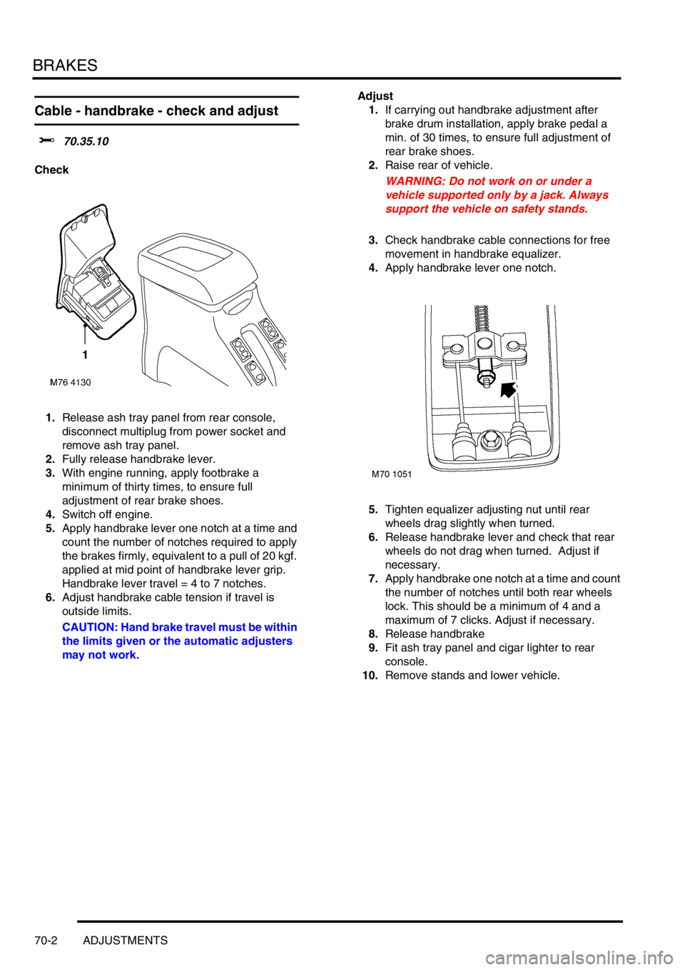
1.Release ash tray panel from rear console,
disconnect multiplug from power socket and
remove ash tray panel.
2.Fully release handbrake lever.
3.With engine running, apply footbrake a
minimum of thirty times, to ensure full
adjustment of rear brake shoes.
4.Switch off engine.
5.Apply handbrake lever one notch at a time and
count the number of notches required to apply
the brakes firmly, equivalent to a pull of 20 kgf.
applied at mid point of handbrake lever grip.
Handbrake lever travel = 4 to 7 notches.
6.Adjust handbrake cable tension if travel is
outside limits.
CAUTION: Hand brake travel must be within
the limits given or the automatic adjusters
may not work.Adjust
1.If carrying out handbrake adjustment after
brake drum installation, apply brake pedal a
min. of 30 times, to ensure full adjustment of
rear brake shoes.
2.Raise rear of vehicle.
WARNING: Do not work on or under a
vehicle supported only by a jack. Always
support the vehicle on safety stands.
3.Check handbrake cable connections for free
movement in handbrake equalizer.
4.Apply handbrake lever one notch.
5.Tighten equalizer adjusting nut until rear
wheels drag slightly when turned.
6.Release handbrake lever and check that rear
wheels do not drag when turned. Adjust if
necessary.
7.Apply handbrake one notch at a time and count
the number of notches until both rear wheels
lock. This should be a minimum of 4 and a
maximum of 7 clicks. Adjust if necessary.
8.Release handbrake
9.Fit ash tray panel and cigar lighter to rear
console.
10.Remove stands and lower vehicle.
Page 560 of 1007
BRAKES
REPAIRS 70-11
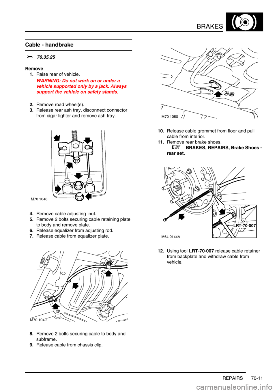
Cable - handbrake
$% 70.35.25
Remove
1.Raise rear of vehicle.
WARNING: Do not work on or under a
vehicle supported only by a jack. Always
support the vehicle on safety stands.
2.Remove road wheel(s).
3.Release rear ash tray, disconnect connector
from cigar lighter and remove ash tray.
4.Remove cable adjusting nut.
5.Remove 2 bolts securing cable retaining plate
to body and remove plate.
6.Release equalizer from adjusting rod.
7.Release cable from equalizer plate.
8.Remove 2 bolts securing cable to body and
subframe.
9.Release cable from chassis clip.10.Release cable grommet from floor and pull
cable from interior.
11.Remove rear brake shoes.
+ BRAKES, REPAIRS, Brake Shoes -
rear set.
12.Using tool LRT-70-007 release cable retainer
from backplate and withdraw cable from
vehicle.
Page 561 of 1007
BRAKES
70-12 REPAIRS
Refit
1.Manoeuvre cable into position and secure floor
grommet.
2.Fit and secure handbrake cable to backplate.
3.Fit brake shoes.
+ BRAKES, REPAIRS, Brake Shoes -
rear set.
4.Align cable clips, fit bolts and tighten to 22 Nm
(16 lbf.ft).
5.Secure cable in chassis clip.
6.Connect handbrake cable to equalizer.
7.Ensure spring is in place and fit equalizer to
adjusting rod.
8.Fit cable adjusting nut.
9.Fit cable retaining plate, fit bolts and tighten to
22 Nm (16 lbf.ft).
10.Adjust handbrake cable.
+ BRAKES, ADJUSTMENTS, Cable -
handbrake - check and adjust.
11.Fit ash tray and cigar lighter to rear console.
12.Fit road wheel(s).
13.Remove stands and lower vehicle.
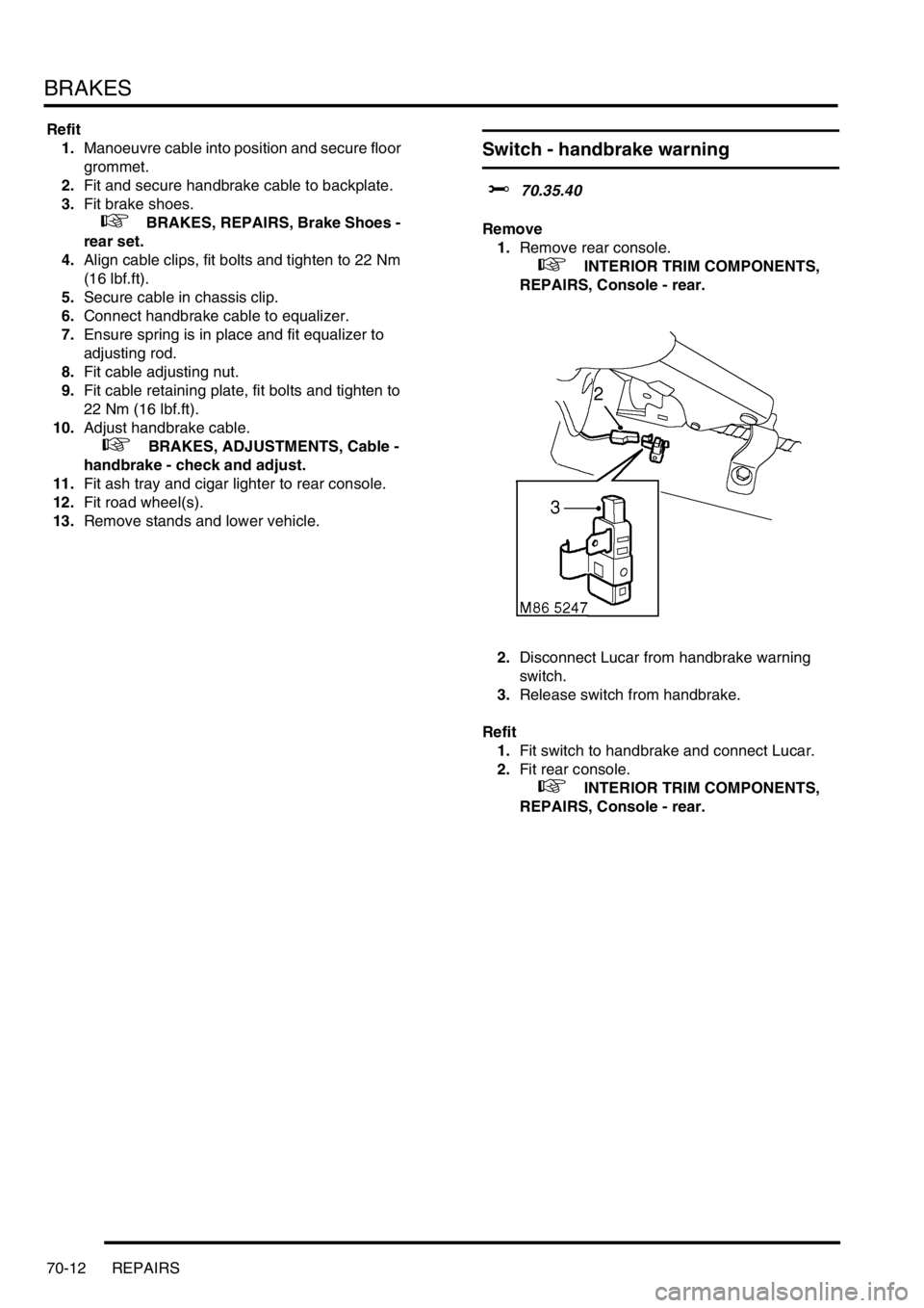
Switch - handbrake warning
$% 70.35.40
Remove
1.Remove rear console.
+ INTERIOR TRIM COMPONENTS,
REPAIRS, Console - rear.
2.Disconnect Lucar from handbrake warning
switch.
3.Release switch from handbrake.
Refit
1.Fit switch to handbrake and connect Lucar.
2.Fit rear console.
+ INTERIOR TRIM COMPONENTS,
REPAIRS, Console - rear.