checking oil LAND ROVER FREELANDER 2001 Workshop Manual
[x] Cancel search | Manufacturer: LAND ROVER, Model Year: 2001, Model line: FREELANDER, Model: LAND ROVER FREELANDER 2001Pages: 1007, PDF Size: 23.47 MB
Page 35 of 1007

GENERAL INFORMATION
03-4
Materials –
lkeep lids on containers of solvents;
lonly use the minimum quantity;
lconsider alternative materials;
lminimise over-spray when painting.
Gases –
luse the correct equipment for collecting
refrigerants;
ldon't burn rubbish on site.
Discharges to water
Most sites will have two systems for discharging
water: storm drains and foul drains. Storm drains
should only receive clean water, foul drains will take
dirty water.
The foul drain will accept many of the normal waste
waters such as washing water, detergents and
domestic type wastes, but oil, petrol, solvent, acids,
hydraulic oil, antifreeze and other such substances
should never be poured down the drain. If in any
doubt, speak to the local Water Company first.
Every precaution must be taken to prevent spillage of
oil, fuel, solvents etc. reaching the drains. All
handling of such materials must take place well away
from the drains and preferably in an area with a kerb
or wall around it, to prevent discharge into the drain.
If a spillage occurs, it should be soaked up
immediately. Having a spill kit available will make this
easier.
Additional precautions
Check whether the surface water drains are
connected to an oil/water separator, this could
reduce the pollution if an incident was to occur. Oil/
water separators require regular maintenance to
ensure effectiveness.
Checklist
Always adhere to the following:
Disposal –
lnever pour anything down a drain without first
checking that it is environmentally safe to do so,
and that it does not contravene any local
regulations or bye-laws;
lhave oil traps emptied regularly.
Spillage prevention –
lstore liquids in a walled area;
lmake sure the taps on liquid containers are
secure and cannot be accidentally turned on;
lprotect bulk storage tanks from vandalism by
locking the valves;
ltransfer liquids from one container to another in
an area away from open drains;
lensure lids are replaced securely on containers;
lhave spill kits available near to points of storage
and handling of liquids.Spill kits
Special materials are available to absorb a number of
different substances. They can be in granular form,
ready to use and bought in convenient containers for
storage. Disposal of used spill-absorbing material is
dealt with in the 'Waste Management' section.
Land contamination
Oils, fuels and solvents etc. can contaminate any soil
that they are allowed to contact. Such materials
should never be disposed of by pouring onto soil and
every precaution must be taken to prevent spillage
reaching soil. Waste materials stored on open
ground could also leak, or have polluting substances
washed off them that would contaminate the land.
Always store these materials in suitable skips or
other similarly robust containers.
Checklist
Always adhere to the following:
ldon't pour or spill anything onto the soil or bare
ground;
ldon't store waste materials on bare ground, see
'Spillage prevention' list.
Legal compliance
Some sites may have a discharge consent for
effluent discharge to the foul drain for a car wash etc.
It is important to know what materials are allowed in
the drain and to check the results of any monitoring
carried out by the Water Company.
Where paint spraying operations are carried out it
may be necessary to apply to the Local Authority for
an air emissions licence to operate the plant. If such
a licence is in operation, additional precautions will
be necessary to comply with the requirements, and
the results of any air quality monitoring must be
checked regularly.
Checklist
Always adhere to the following:
lknow what legal consents and licences apply to
the operations;
lcheck that the emissions and discharges
comply with legal requirements.
Page 38 of 1007

GENERAL INFORMATION
03-7
General fitting instructions
Precautions against damage
To avoid damage to the vehicle when carrying out
repairs, always adhere to the following:
lAlways fit wing and seat covers before
commencing work. Avoid spilling brake fluid or
battery acid on paintwork; immediately wash off
with water if this occurs.
lDisconnect the battery earth lead before starting
work, see ELECTRICAL PRECAUTIONS.
lAlways use the recommended service tool or a
satisfactory equivalent where specified.
lProtect exposed bearing surfaces, sealing
surfaces and screw threads from damage.
Component removal
Whenever possible, clean components and
surrounding area before removal.
lBlank off openings exposed by component
removal.
lImmediately seal fuel, oil or hydraulic lines when
apertures are exposed; use plastic caps or
plugs to prevent loss of fluid and ingress of dirt.
lClose open ends of oilways exposed by
component removal with tapered hardwood
plugs or conspicuous plastic plugs.
lImmediately a component is removed, place it in
a suitable container; use a separate container
for each component and its associated parts.
lClean bench and provide marking materials,
labels, containers and locking wire before
dismantling a component.
Dismantling
Observe scrupulous cleanliness when dismantling
components, particularly when brake, fuel or
hydraulic system parts are being worked on. A
particle of dirt or a cloth fragment could cause a
serious malfunction if trapped in these systems.Use the following procedures:
lBlow out all tapped holes, crevices, oilways and
fluid passages with an air line. Ensure that any
O-rings used for sealing are correctly replaced
or renewed if disturbed during the process.
lUse marking ink to identify mating parts and
ensure correct reassembly. Do not use a centre
punch or scriber to mark parts, they could
initiate cracks or distortion in marked
components.
lWire together mating parts where necessary to
prevent accidental interchange (e.g. roller
bearing components).
lWire labels on to all parts which are to be
renewed, and to parts requiring further
inspection before being passed for reassembly;
place these parts in separate containers from
those containing parts for rebuild.
lDo not discard a part due for renewal until after
comparing it with a new part to ensure that its
correct replacement has been obtained.
Cleaning components
Always use the recommended cleaning agent or
equivalent. Ensure that adequate ventilation is
provided when volatile degreasing agents are being
used. Do not use degreasing equipment for
components containing items which could be
damaged by the use of this process.
When washing under bonnet, never direct water onto
ECM, as water ingress may occur resulting in
damage to electrical components inside.
General Inspection
All components should be inspected for wear or
damage before being reassembled.
lNever inspect a component for wear or
dimensional check unless it is absolutely clean;
a slight smear of grease can conceal an
incipient failure.
lWhen a component is to be checked
dimensionally against recommended values,
use the appropriate measuring equipment
(surface plates, micrometers, dial gauges etc.).
Ensure the measuring equipment is calibrated
and in good serviceable condition.
lReject a component if its dimensions are
outside the specified tolerances, or if it appears
to be damaged.
lA part may be refitted if its critical dimension is
exactly to its tolerance limit and it appears to be
in satisfactory condition.
lUse 'Plastigauge' 12 Type PG-1 for checking
bearing surface clearances.
Page 166 of 1007

MAINTENANCE
MAINTENANCE 10-19
Manual Gearbox – GETRAG
Replace Fluid
WARNING: Avoid excessive skin contact
with mineral oil. Mineral oils remove the
natural fats from the skin, leading to
dryness, irritation and dermatitis.
1.Replace gearbox fluid.
+ MANUAL GEARBOX - GETRAG,
ADJUSTMENTS, Gearbox oil - drain and
refill.
Automatic Gearbox – JATCO
Check and top-up fluid
WARNING: Avoid excessive skin contact
with mineral oil. Mineral oils remove the
natural fats from the skin, leading to
dryness, irritation and dermatitis.
1.Position vehicle on ramp.
2.Apply handbrake and position chocks under
front and rear wheels.
3.Remove underbelly panel.
+ EXTERIOR FITTINGS, REPAIRS,
Panel - underbelly.
4.Connect TestBook/T4 to monitor gearbox fluid
temperature.
CAUTION: The gearbox fluid level must only
be checked when the temperature of the
fluid is between 35° and 45°. The reading
obtained will be incorrect if the fluid is
outside this temperature range.
5.Start engine, move selector lever from 'P'
through all gear positions, pausing in each gear
position for 2-3 seconds and return to 'P'
position.
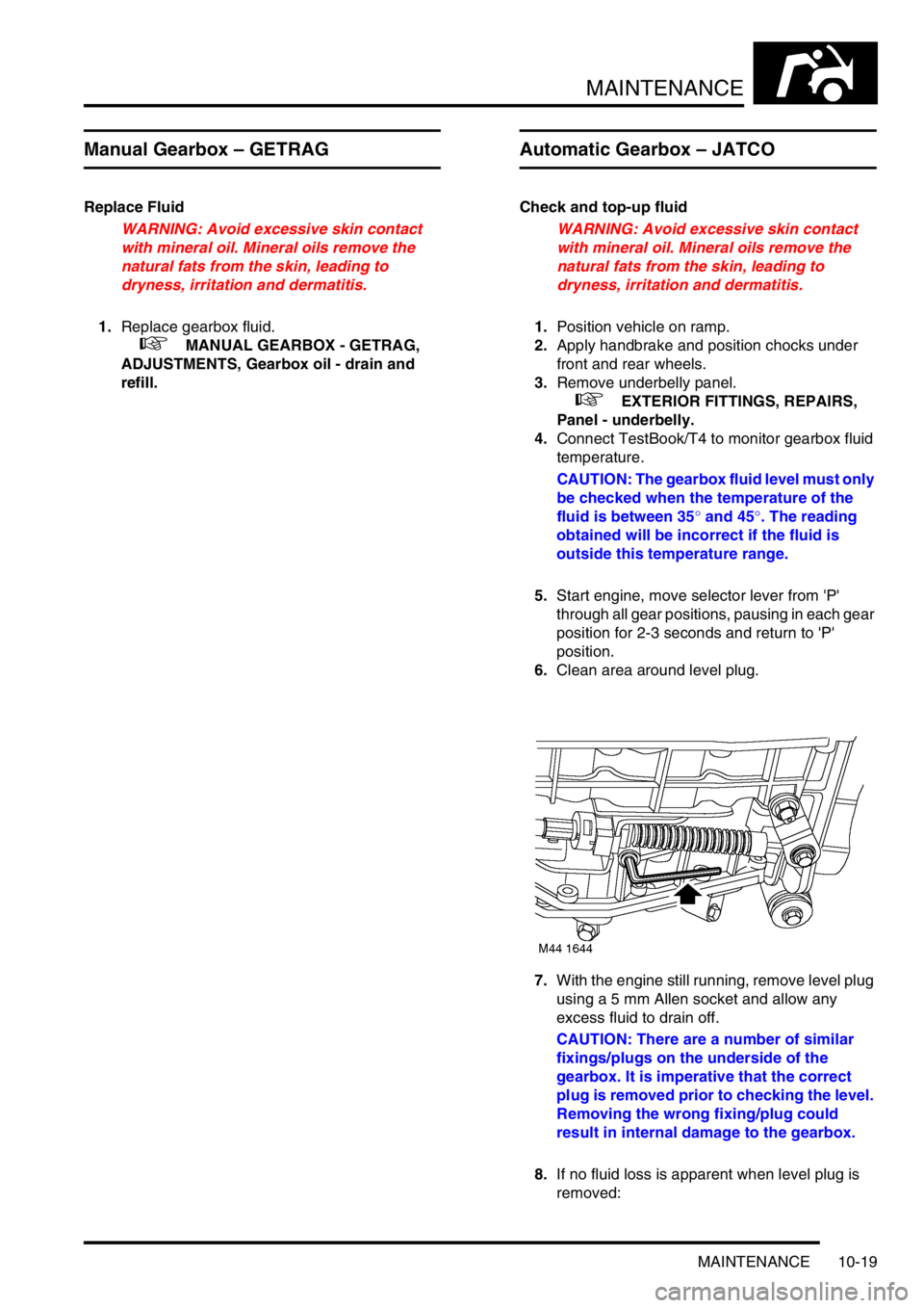
6.Clean area around level plug.
7.With the engine still running, remove level plug
using a 5 mm Allen socket and allow any
excess fluid to drain off.
CAUTION: There are a number of similar
fixings/plugs on the underside of the
gearbox. It is imperative that the correct
plug is removed prior to checking the level.
Removing the wrong fixing/plug could
result in internal damage to the gearbox.
8.If no fluid loss is apparent when level plug is
removed:
Page 446 of 1007

AUTOMATIC GEARBOX - JATCO
REPAIRS 44-11
Oil seal - torque converter
$% 44.17.11
Remove
1.Remove gearbox assembly.
+ AUTOMATIC GEARBOX - JATCO,
REPAIRS, Gearbox - KV6.
+ AUTOMATIC GEARBOX - JATCO,
REPAIRS, Gearbox - Td4.
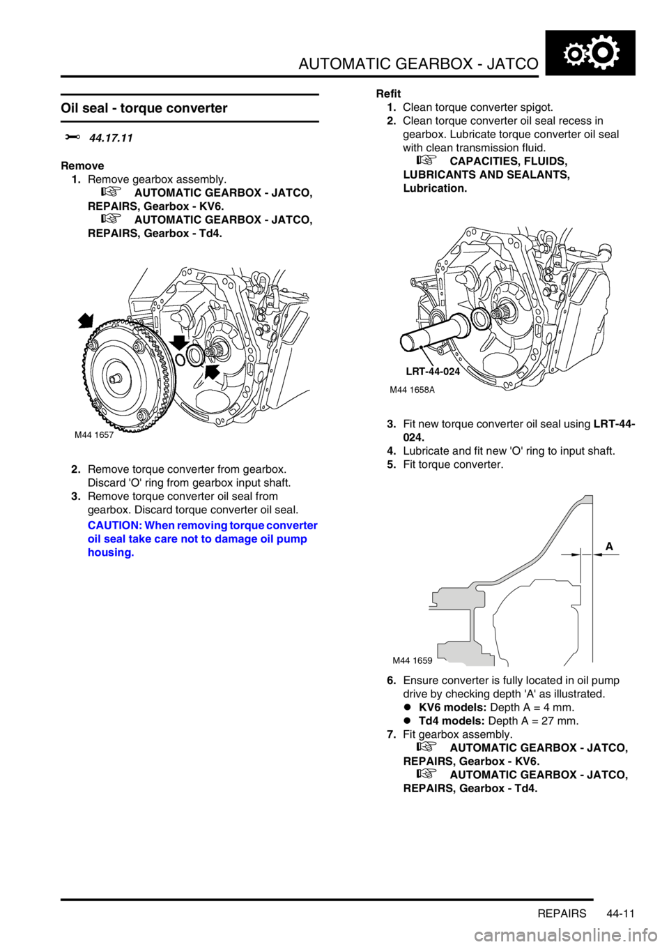
2.Remove torque converter from gearbox.
Discard 'O' ring from gearbox input shaft.
3.Remove torque converter oil seal from
gearbox. Discard torque converter oil seal.
CAUTION: When removing torque converter
oil seal take care not to damage oil pump
housing.Refit
1.Clean torque converter spigot.
2.Clean torque converter oil seal recess in
gearbox. Lubricate torque converter oil seal
with clean transmission fluid.
+ CAPACITIES, FLUIDS,
LUBRICANTS AND SEALANTS,
Lubrication.
3.Fit new torque converter oil seal using LRT-44-
024.
4.Lubricate and fit new 'O' ring to input shaft.
5.Fit torque converter.
6.Ensure converter is fully located in oil pump
drive by checking depth 'A' as illustrated.
lKV6 models: Depth A = 4 mm.
lTd4 models: Depth A = 27 mm.
7.Fit gearbox assembly.
+ AUTOMATIC GEARBOX - JATCO,
REPAIRS, Gearbox - KV6.
+ AUTOMATIC GEARBOX - JATCO,
REPAIRS, Gearbox - Td4.
M44 1659
A
Page 451 of 1007

AUTOMATIC GEARBOX - JATCO
44-16 REPAIRS
35.Remove 2 top bolts securing gearbox to
engine.
36.Release gearbox from 2 dowels.
37.Remove gearbox assembly.
38.Fit converter retaining plate and secure with
bolts.Refit
1.Remove torque converter retaining plate.
2.Ensure converter is fully located in oil pump
drive by checking depth 'A' as illustrated. Depth
A = 4 mm.
3.Clean gearbox to engine mating faces, dowels
and dowel holes.
4.Fit gearbox assembly.
5.Fit bolts securing gearbox and tighten to 85 Nm
(63 lbf.ft).
6.Disconnect lifting equipment.
7.Clean CKP sensor and mating face.
8.Fit CKP sensor, fit bolt and tighten to 9 Nm (7
lbf.ft).
9.Position fluid cooler, tighten M12 bolts to 85 Nm
(63 lbf.ft) and M8 bolt to 25 Nm (18 lbf.ft).
10.Connect hoses to fluid cooler.
11.Clean fluid cooler unions.
12.Lubricate new 'O' rings with clean transmission
fluid and fit 'O' rings to fluid cooler hoses.
+ CAPACITIES, FLUIDS,
LUBRICANTS AND SEALANTS,
Lubrication.
13.Connect fluid cooler hoses to gearbox and
tighten unions to 18 Nm (13 lbf.ft).
14.Clean starter motor mating faces.
15.Position starter motor to gearbox, align CKP
sensor multiplug bracket, fit and tighten bolts to
45 Nm (33 lbf.ft).
16.Using gearbox bracket bolts, secure LRT-44-
026 lifting bracket to gearbox.
17.Position IRD cooling hose retainer, fit bolt and
tighten to 25 Nm (18 lbf.ft).
18.Align marks on drive plate to torque converter.
19.Fit bolts securing drive plate to torque converter
and tighten bolts to 45 Nm (33 lbf.ft).
20.Clean torque converter access plate.
M44 1689
A
M44 1668
Page 457 of 1007

AUTOMATIC GEARBOX - JATCO
44-22 REPAIRS
42.Remove 2 top bolts securing gearbox to
engine.
43.Release gearbox from 2 dowels.
44.Manoeuvre and lower gearbox to floor.
45.Fit converter retaining plate and secure with
bolts.Refit
1.Remove torque converter retaining plate.
2.Ensure converter is fully located in oil pump
drive by checking depth 'A' as illustrated. Depth
A = 4 mm.
3.Clean gearbox to engine mating faces, dowels
and dowel holes.
4.Fit gearbox assembly.
5.Fit bolts securing gearbox and tighten to 85 Nm
(63 lbf.ft).
6.Position LH mounting bracket to gearbox, fit
and tighten bolts to 85 Nm (63 lbf.ft).
7.Position LH mounting to body, fit and tighten
bolts to 48 Nm (35 lbf.ft).
8.Align gearbox bracket to LH body mounting, fit
and tighten through bolt to 100 Nm (74 lbf.ft).
9.Disconnect lifting equipment.
10.Remove nuts and bolts securing lifting brackets
to gearbox and remove brackets.
11.Connect engine and gearbox harness
multiplugs to main harness.
12.Secure multiplugs to clips.
13.Position engine earth lead and secure with bolt.
14.Fit starter motor.
+ CHARGING AND STARTING,
REPAIRS, Starter motor - KV6.
15.Clean throttle housing and manifold chamber
mating faces.
16.Fit new seal to inlet manifold chamber.
17.Position throttle housing to manifold chamber,
fit Torx screws and tighten to 7 Nm (7 lbf.ft).
18.Connect throttle inner cable to throttle cam and
secure outer cable in abutment bracket, if fitted.
19.Connect hose to cruise control actuator.
20.Secure breather hoses to throttle housing, if
fitted.
21.Adjust throttle cable, if fitted.
+ FUEL DELIVERY SYSTEM -
PETROL, ADJUSTMENTS, Throttle cable -
check and adjust - KV6.
22.Clean CKP sensor and mating face.
M44 1689
A
M44 1668
Page 461 of 1007

AUTOMATIC GEARBOX - JATCO
44-26 REPAIRS
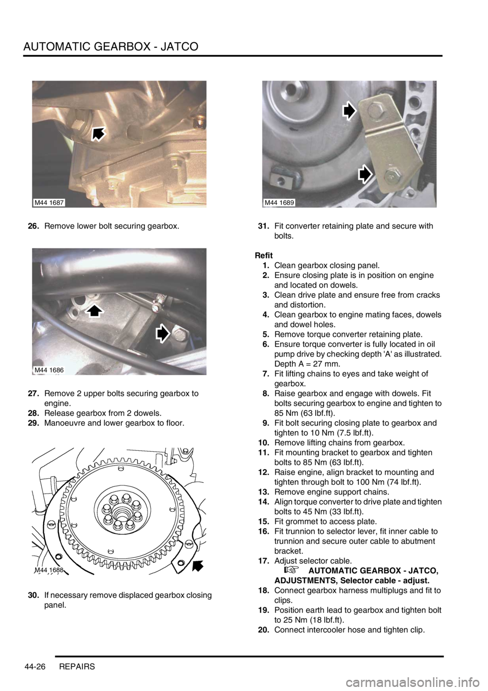
26.Remove lower bolt securing gearbox.
27.Remove 2 upper bolts securing gearbox to
engine.
28.Release gearbox from 2 dowels.
29.Manoeuvre and lower gearbox to floor.
30.If necessary remove displaced gearbox closing
panel.31.Fit converter retaining plate and secure with
bolts.
Refit
1.Clean gearbox closing panel.
2.Ensure closing plate is in position on engine
and located on dowels.
3.Clean drive plate and ensure free from cracks
and distortion.
4.Clean gearbox to engine mating faces, dowels
and dowel holes.
5.Remove torque converter retaining plate.
6.Ensure torque converter is fully located in oil
pump drive by checking depth 'A' as illustrated.
Depth A = 27 mm.
7.Fit lifting chains to eyes and take weight of
gearbox.
8.Raise gearbox and engage with dowels. Fit
bolts securing gearbox to engine and tighten to
85 Nm (63 lbf.ft).
9.Fit bolt securing closing plate to gearbox and
tighten to 10 Nm (7.5 lbf.ft).
10.Remove lifting chains from gearbox.
11.Fit mounting bracket to gearbox and tighten
bolts to 85 Nm (63 lbf.ft).
12.Raise engine, align bracket to mounting and
tighten through bolt to 100 Nm (74 lbf.ft).
13.Remove engine support chains.
14.Align torque converter to drive plate and tighten
bolts to 45 Nm (33 lbf.ft).
15.Fit grommet to access plate.
16.Fit trunnion to selector lever, fit inner cable to
trunnion and secure outer cable to abutment
bracket.
17.Adjust selector cable.
+ AUTOMATIC GEARBOX - JATCO,
ADJUSTMENTS, Selector cable - adjust.
18.Connect gearbox harness multiplugs and fit to
clips.
19.Position earth lead to gearbox and tighten bolt
to 25 Nm (18 lbf.ft).
20.Connect intercooler hose and tighten clip.
M44 1687
M44 1686
M44 1689