wheel alignment LAND ROVER FREELANDER 2001 Workshop Manual
[x] Cancel search | Manufacturer: LAND ROVER, Model Year: 2001, Model line: FREELANDER, Model: LAND ROVER FREELANDER 2001Pages: 1007, PDF Size: 23.47 MB
Page 13 of 1007

CONTENTS
10 CONTENTS
REAR AXLE & FINAL DRIVE ................................................................... 51-1
REPAIRS
Differential assembly ..................................................................................................................... 51-1
Cover - rear - differential ................................................................................................................. 51-2
Bush - differential mounting - front ................................................................................................. 51-3
Bush - differential mounting - rear ................................................................................................. 51-4
Oil seal - pinion .............................................................................................................................. 51-5
Oil seal - differential housing ......................................................................................................... 51-6
STEERING ................................................................................................ 57-1
ADJUSTMENTS
Power assisted steering (PAS) system - bleed............................................................................... 57-1
Cable - key interlock - adjust .......................................................................................................... 57-1
Front wheel alignment - check & adjust .......................................................................................... 57-2
Alignment - rear wheel - check & adjust ......................................................................................... 57-3
Power steering - pressure test ........................................................................................................ 57-4
REPAIRS
Power steering rack ........................................................................................................................ 57-5
Gaiter - PAS rack ............................................................................................................................ 57-8
Oil cooler - Td4 & K1.8 models ....................................................................................................... 57-9
Oil cooler - KV6 models .................................................................................................................. 57-10
Drive belt - K1.8 .............................................................................................................................. 57-11
Pump - steering - KV6 .................................................................................................................... 57-12
Pump - steering - K1.8 .................................................................................................................... 57-14
Pump - steering - Td4 ..................................................................................................................... 57-15
Nacelle - column ............................................................................................................................. 57-16
Column lock & ignition/starter switch assembly .............................................................................. 57-17
Cable - key interlock ....................................................................................................................... 57-18
Column assembly - inner & outer ................................................................................................... 57-19
Ball joint - track rod ......................................................................................................................... 57-23
Track rod......................................................................................................................................... 57-24
Steering wheel ................................................................................................................................ 57-25
FRONT SUSPENSION .............................................................................. 60-1
REPAIRS
Anti roll bar...................................................................................................................................... 60-1
Ball joint link - anti roll bar .............................................................................................................. 60-2
Mounting rubbers - anti roll bar - set .............................................................................................. 60-2
Bearing - hub ................................................................................................................................. 60-3
Damper .......................................................................................................................................... 60-7
Lower arm assembly ...................................................................................................................... 60-10
Rear beam ..................................................................................................................................... 60-13
Bush - lower arm - front .................................................................................................................. 60-15
Bush - lower arm - rear ................................................................................................................... 60-16
Page 90 of 1007
GENERAL DATA
04-27
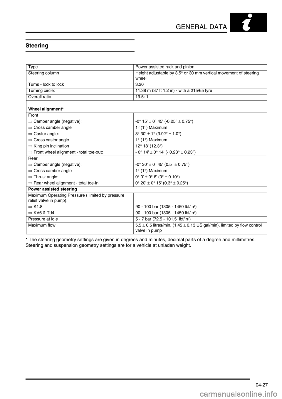
Steering
* The steering geometry settings are given in degrees and minutes, decimal parts of a degree and millimetres.
Steering and suspension geometry settings are for a vehicle at unladen weight.
Type Power assisted rack and pinion
Steering column Height adjustable by 3.5° or 30 mm vertical movement of steering
wheel
Turns - lock to lock 3.20
Turning circle: 11.38 m (37 ft 1.2 in) - with a 215/65 tyre
Overall ratio 19.5: 1
Wheel alignment*
Front
⇒ Camber angle (negative): -0° 15' ± 0° 45' (-0.25° ± 0.75°)
⇒ Cross camber angle 1° (1°) Maximum
⇒ Castor angle: 3° 30' ± 1° (3.92° ± 1.0°)
⇒ Cross castor angle 1° (1°) Maximum
⇒ King pin inclination 12° 18' (12.3°)
⇒ Front wheel alignment - total toe-out: - 0° 14' ± 0° 14' (- 0.23° ± 0.23°)
Rear
⇒ Camber angle (negative): -0° 30' ± 0° 45' (0.5° ± 0.75°)
⇒ Cross camber angle 1° (1°) Maximum
⇒ Thrust angle: 0° 0' ± 0° 6' (0° ± 0.10°)
⇒ Rear wheel alignment - total toe-in: 0° 20' ± 0° 15' (0.3° ± 0.25°)
Power assisted steering
Maximum Operating Pressure ( limited by pressure
relief valve in pump):
⇒ K1.8 90 - 100 bar (1305 - 1450 lbf/in
2)
⇒ KV6 & Td4 90 - 100 bar (1305 - 1450 lbf/in
2)
Pressure at idle 5 - 7 bar (72.5 - 101.5 lbf/in
2)
Maximum flow 5.5 ± 0.5 litres/min. (1.45 ± 0.13 US gal/min), limited by flow control
valve in pump
Page 249 of 1007
ENGINE - K SERIES KV6
12-3-72 REPAIRS
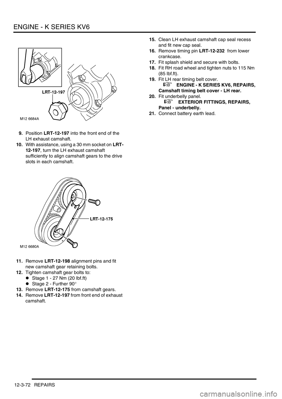
9.Position LRT-12-197 into the front end of the
LH exhaust camshaft.
10.With assistance, using a 30 mm socket on LRT-
12-197, turn the LH exhaust camshaft
sufficiently to align camshaft gears to the drive
slots in each camshaft.
11.Remove LRT-12-198 alignment pins and fit
new camshaft gear retaining bolts.
12.Tighten camshaft gear bolts to:
lStage 1 - 27 Nm (20 lbf.ft)
lStage 2 - Further 90°
13.Remove LRT-12-175 from camshaft gears.
14.Remove LRT-12-197 from front end of exhaust
camshaft.15.Clean LH exhaust camshaft cap seal recess
and fit new cap seal.
16.Remove timing pin LRT-12-232 from lower
crankcase.
17.Fit splash shield and secure with bolts.
18.Fit RH road wheel and tighten nuts to 115 Nm
(85 lbf.ft).
19.Fit LH rear timing belt cover.
+ ENGINE - K SERIES KV6, REPAIRS,
Camshaft timing belt cover - LH rear.
20.Fit underbelly panel.
+ EXTERIOR FITTINGS, REPAIRS,
Panel - underbelly.
21.Connect battery earth lead.
Page 253 of 1007
ENGINE - K SERIES KV6
12-3-76 REPAIRS
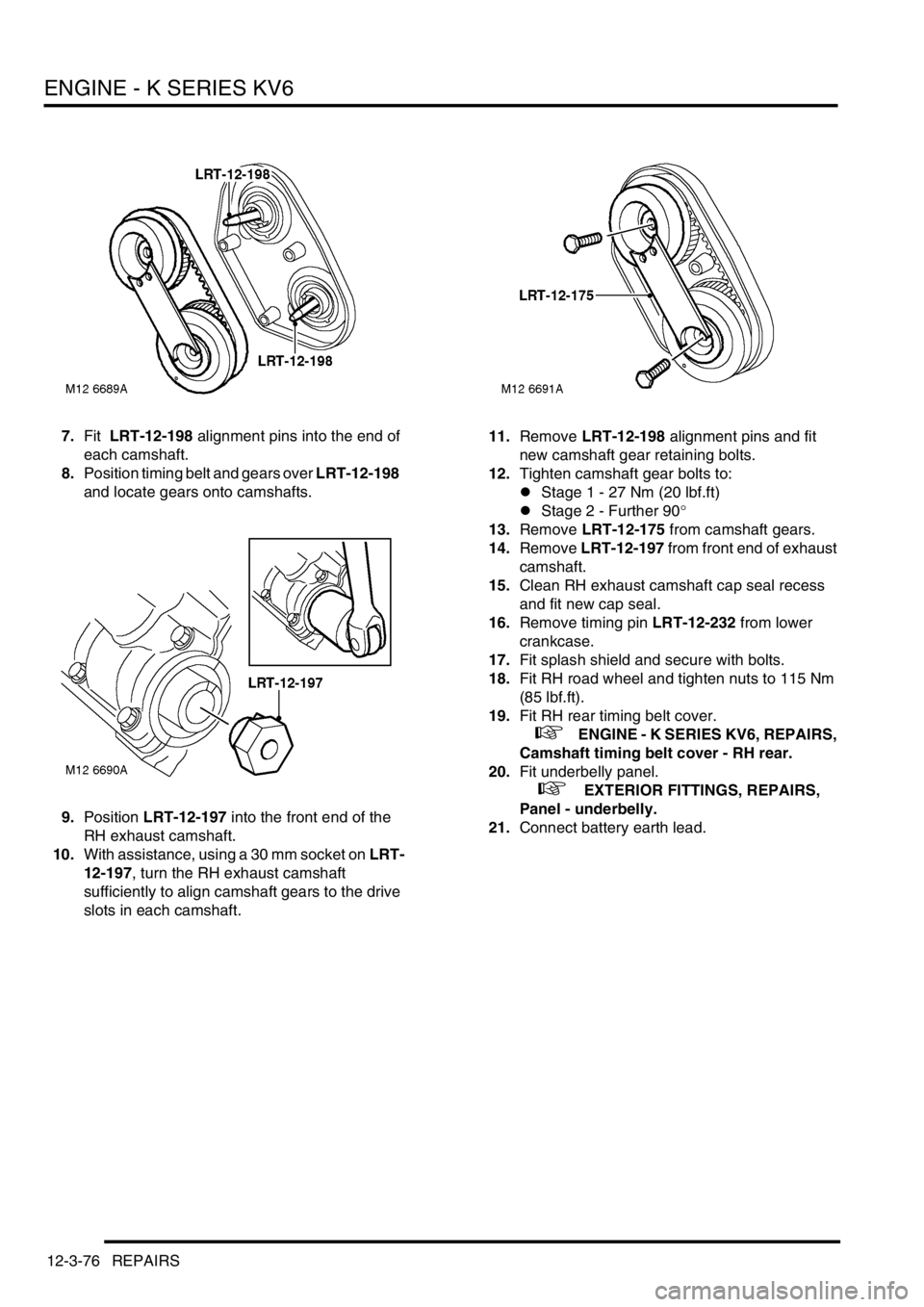
7.Fit LRT-12-198 alignment pins into the end of
each camshaft.
8.Position timing belt and gears over LRT-12-198
and locate gears onto camshafts.
9.Position LRT-12-197 into the front end of the
RH exhaust camshaft.
10.With assistance, using a 30 mm socket on LRT-
12-197, turn the RH exhaust camshaft
sufficiently to align camshaft gears to the drive
slots in each camshaft.11.Remove LRT-12-198 alignment pins and fit
new camshaft gear retaining bolts.
12.Tighten camshaft gear bolts to:
lStage 1 - 27 Nm (20 lbf.ft)
lStage 2 - Further 90°
13.Remove LRT-12-175 from camshaft gears.
14.Remove LRT-12-197 from front end of exhaust
camshaft.
15.Clean RH exhaust camshaft cap seal recess
and fit new cap seal.
16.Remove timing pin LRT-12-232 from lower
crankcase.
17.Fit splash shield and secure with bolts.
18.Fit RH road wheel and tighten nuts to 115 Nm
(85 lbf.ft).
19.Fit RH rear timing belt cover.
+ ENGINE - K SERIES KV6, REPAIRS,
Camshaft timing belt cover - RH rear.
20.Fit underbelly panel.
+ EXTERIOR FITTINGS, REPAIRS,
Panel - underbelly.
21.Connect battery earth lead.
Page 495 of 1007
STEERING
57-2 ADJUSTMENTS
Front wheel alignment - check & adjust
$% 57.65.01
Check
1.Ensure tyre pressures are correct and vehicle
is at kerbside weight.
2.Roll vehicle backwards and forwards to relieve
stresses in steering and suspension.
3.Ensure that wheel alignment equipment is
properly calibrated.
4.Check front wheel alignment is within
tolerance.
+ GENERAL DATA, Steering.
Adjust
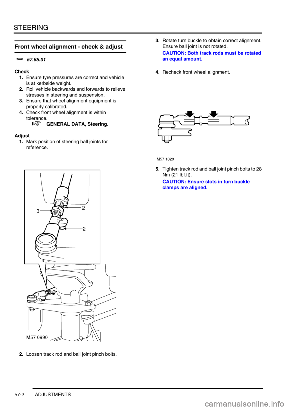
1.Mark position of steering ball joints for
reference.
2.Loosen track rod and ball joint pinch bolts.3.Rotate turn buckle to obtain correct alignment.
Ensure ball joint is not rotated.
CAUTION: Both track rods must be rotated
an equal amount.
4.Recheck front wheel alignment.
5.Tighten track rod and ball joint pinch bolts to 28
Nm (21 lbf.ft).
CAUTION: Ensure slots in turn buckle
clamps are aligned.
Page 496 of 1007
STEERING
ADJUSTMENTS 57-3
Alignment - rear wheel - check & adjust
$% 57.65.06
Check
1.Ensure tyre pressures are correct and vehicle
is at kerbside weight.
2.Roll vehicle backwards and forwards to relieve
stresses in steering and suspension.
3.Ensure that wheel alignment equipment is
properly calibrated.
4.Check front wheel alignment is within
tolerance.
+ GENERAL DATA, Steering.
5.Check rear wheel alignment is within tolerance.
+ GENERAL DATA, Steering.Adjust
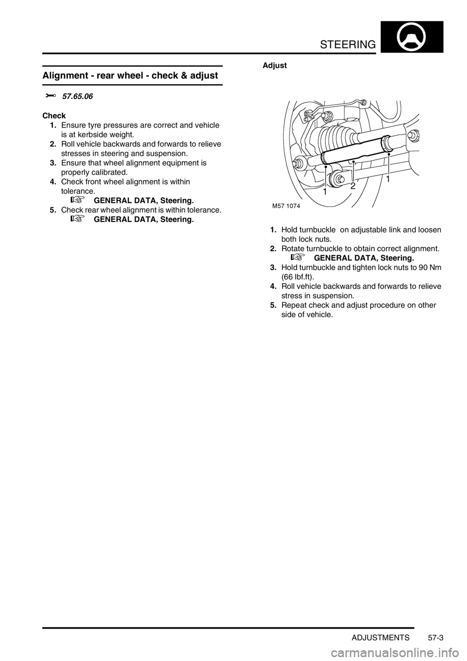
1.Hold turnbuckle on adjustable link and loosen
both lock nuts.
2.Rotate turnbuckle to obtain correct alignment.
+ GENERAL DATA, Steering.
3.Hold turnbuckle and tighten lock nuts to 90 Nm
(66 lbf.ft).
4.Roll vehicle backwards and forwards to relieve
stress in suspension.
5.Repeat check and adjust procedure on other
side of vehicle.
Page 500 of 1007
STEERING
REPAIRS 57-7
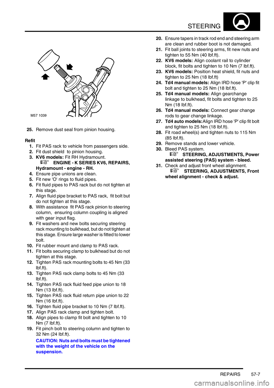
25.Remove dust seal from pinion housing.
Refit
1.Fit PAS rack to vehicle from passengers side.
2.Fit dust shield to pinion housing.
3. KV6 models: Fit RH Hydramount.
+ ENGINE - K SERIES KV6, REPAIRS,
Hydramount - engine - RH.
4.Ensure pipe unions are clean.
5.Fit new 'O' rings to fluid pipes.
6.Fit fluid pipes to PAS rack but do not tighten at
this stage.
7.Align fluid pipe bracket to PAS rack, fit bolt but
do not tighten at this stage.
8.With assistance fit PAS rack pinion to steering
column, ensuring column coupling is aligned
with gear input flag.
9.Fit washers and new bolts securing steering
rack mounting to bulkhead, but do not tighten at
this stage. Ensure large washer is fitted to lower
bolt.
10.Fit rubber mount and clamp to PAS rack.
11.Fit bolts securing clamp to bulkhead but do not
tighten at this stage.
12.Tighten PAS rack mounting bolts to 45 Nm (33
lbf.ft).
13.Tighten PAS rack clamp bolts to 45 Nm (33
lbf.ft).
14.Tighten PAS rack fluid feed pipe union to 18
Nm (13 lbf.ft).
15.Tighten PAS rack fluid return pipe union to 22
Nm (16 lbf.ft).
16.Tighten fluid pipe bracket to 10 Nm (7 lbf.ft).
17.Align PAS rack clamp and tighten bolt.
18.Align pipes to clamp fit bolt and tighten to 10
Nm (7 lbf.ft).
19.Fit pinch bolt to steering column and tighten to
32 Nm (24 lbf.ft).
CAUTION: Nuts and bolts must be tightened
with the weight of the vehicle on the
suspension.20.Ensure tapers in track rod end and steering arm
are clean and rubber boot is not damaged.
21.Fit ball joints to steering arms, fit new nuts and
tighten to 55 Nm (40 lbf.ft).
22. KV6 models: Align coolant rail to cylinder
block, fit bolts and tighten to 10 Nm (7 lbf.ft).
23. KV6 models: Position heat shield, fit nuts and
tighten to 25 Nm (18 lbf.ft)
24. Td4 manual models: Align IRD hose 'P' clip fit
bolt and tighten to 25 Nm (18 lbf.ft).
25. Td4 manual models: Align gearchange
linkage to bulkhead, fit bolts and tighten to 25
Nm (18 lbf.ft).
26. Td4 manual models: Connect gear change
rods to gear change linkage.
27. Td4 auto models:Align IRD hose 'P' clip fit bolt
and tighten to 25 Nm (18 lbf.ft).
28.Fit road wheel(s) and tighten nuts to 115 Nm
(85 lbf.ft).
29.Remove stands and lower vehicle.
30.Bleed PAS system.
+ STEERING, ADJUSTMENTS, Power
assisted steering (PAS) system - bleed.
31.Check and adjust front wheel alignment.
+ STEERING, ADJUSTMENTS, Front
wheel alignment - check & adjust.
Page 516 of 1007
STEERING
REPAIRS 57-23
Ball joint - track rod
$% 57.55.07
Remove
1.Raise front of vehicle.
WARNING: Do not work on or under a
vehicle supported only by a jack. Always
support the vehicle on safety stands.
2.Remove front road wheel.
3.Remove pinch bolt securing ball joint to
turnbuckle.
4.Remove nut from ball joint and discard.
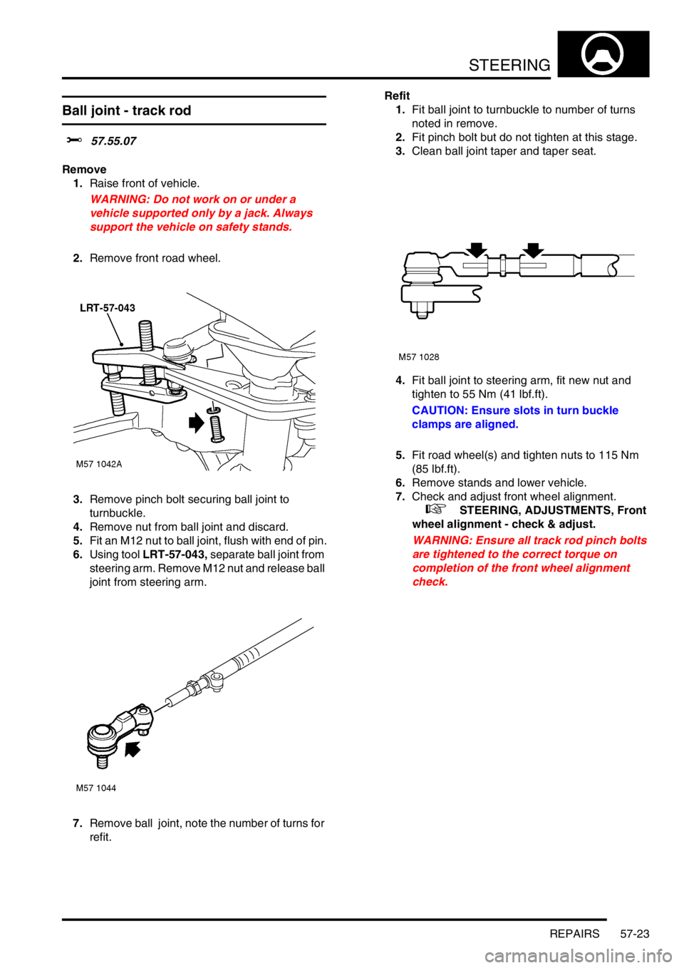
5.Fit an M12 nut to ball joint, flush with end of pin.
6.Using tool LRT-57-043, separate ball joint from
steering arm. Remove M12 nut and release ball
joint from steering arm.
7.Remove ball joint, note the number of turns for
refit.Refit
1.Fit ball joint to turnbuckle to number of turns
noted in remove.
2.Fit pinch bolt but do not tighten at this stage.
3.Clean ball joint taper and taper seat.
4.Fit ball joint to steering arm, fit new nut and
tighten to 55 Nm (41 lbf.ft).
CAUTION: Ensure slots in turn buckle
clamps are aligned.
5.Fit road wheel(s) and tighten nuts to 115 Nm
(85 lbf.ft).
6.Remove stands and lower vehicle.
7.Check and adjust front wheel alignment.
+ STEERING, ADJUSTMENTS, Front
wheel alignment - check & adjust.
WARNING: Ensure all track rod pinch bolts
are tightened to the correct torque on
completion of the front wheel alignment
check.
Page 517 of 1007
STEERING
57-24 REPAIRS
Track rod
$% 57.55.09
Remove
1. Td4 & KV6 models: Remove steering rack.
+ STEERING, REPAIRS, Power
steering rack.
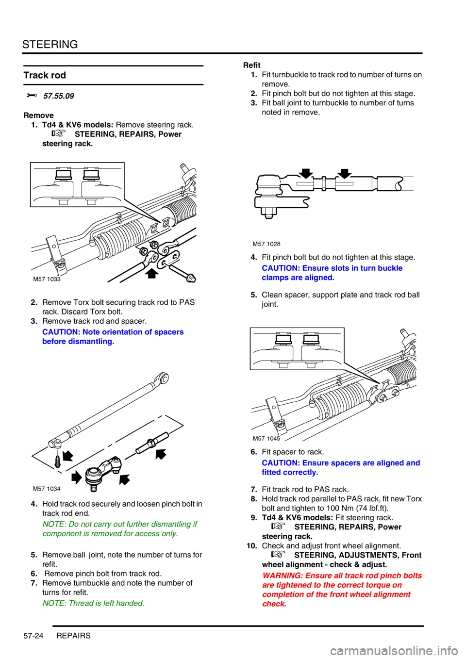
2.Remove Torx bolt securing track rod to PAS
rack. Discard Torx bolt.
3.Remove track rod and spacer.
CAUTION: Note orientation of spacers
before dismantling.
4.Hold track rod securely and loosen pinch bolt in
track rod end.
NOTE: Do not carry out further dismantling if
component is removed for access only.
5.Remove ball joint, note the number of turns for
refit.
6. Remove pinch bolt from track rod.
7.Remove turnbuckle and note the number of
turns for refit.
NOTE: Thread is left handed.Refit
1.Fit turnbuckle to track rod to number of turns on
remove.
2.Fit pinch bolt but do not tighten at this stage.
3.Fit ball joint to turnbuckle to number of turns
noted in remove.
4.Fit pinch bolt but do not tighten at this stage.
CAUTION: Ensure slots in turn buckle
clamps are aligned.
5.Clean spacer, support plate and track rod ball
joint.
6.Fit spacer to rack.
CAUTION: Ensure spacers are aligned and
fitted correctly.
7.Fit track rod to PAS rack.
8.Hold track rod parallel to PAS rack, fit new Torx
bolt and tighten to 100 Nm (74 lbf.ft).
9. Td4 & KV6 models: Fit steering rack.
+ STEERING, REPAIRS, Power
steering rack.
10.Check and adjust front wheel alignment.
+ STEERING, ADJUSTMENTS, Front
wheel alignment - check & adjust.
WARNING: Ensure all track rod pinch bolts
are tightened to the correct torque on
completion of the front wheel alignment
check.
Page 529 of 1007

FRONT SUSPENSION
60-10 REPAIRS
Refit
1.Inspect damper, spring mounting rubbers and
bearing for deterioration and damage.
2.Clean mating faces of spring, mounting and
mounting plate.
3.Clean damper shaft and bump stop plate.
4.Position spring and damper assembly to spring
compressor. Compress spring.
5.Fit damper to spring, ensure spring locates in
cut recess in damper plate.
6.Fit bump cup, bump stop and dust cover to
damper.
7.Fit spring aid and bump plate.
8.Fit mounting plate and rebound washer.
9.Using new nut, hold damper shaft with Allen
key and tighten nut to 57 Nm (42 lbf.ft).
CAUTION: Note alignment of top mounting,
spring and damper dust cover.
10.Release and remove spring from compressor.
11.Clean mating face of top mounting plate.
12.Position damper assembly and align top
mounting to body, fit nuts and tighten to 45 Nm
(33 lbf.ft).
13. LH side: Position fusebox, fit nuts and tighten
to 8 Nm (6 lbf.ft).
14. LH side: Connect positive and negative leads,
fit bolts and tighten to 8 Nm (6 lbf.ft).
15. LH side: Connect multiplug to fusebox.
16. RH side: Position coolant reservoir and secure
with bolt.
17.Fit hub to damper, fit nuts and bolts and tighten
to 205 Nm (151 lbf.ft).
18.Clean anti-roll bar link taper and mating face.
19.Connect anti-roll bar link, fit new nut and tighten
to 55 Nm (41 lbf.ft).
CAUTION: Use a spanner and an Allen key
to prevent ball joint rotating when undoing
link.
20.Clean track rod taper and mating face.
21.Connect track rod end to steering arm using
new nut and tighten nut to 55 Nm (41 lbf.ft).
22.Clean ABS sensor, smear sensor with an anti-
seize grease and fit sensor to hub.
CAUTION: Ensure ABS sensor is fully
located into hub, so that sensor touches
pole wheel teeth.
23.Position ABS harness and brake hose in
bracket and secure with clip.
24.Fit road wheel(s) and tighten nuts to 115 Nm
(85 lbf.ft).
25.Remove stand and lower vehicle.
26.Connect battery earth lead.
Lower arm assembly
$% 60.35.02
Remove
1.Raise front of vehicle.
WARNING: Do not work on or under a
vehicle supported only by a jack. Always
support the vehicle on safety stands.
2.Remove road wheel.
3.Remove underbelly panel.
+ EXTERIOR FITTINGS, REPAIRS,
Panel - underbelly.
4.Release stake in drive shaft nuts.
5.With an assistant applying brakes, remove and
discard drive shaft hub nut.
6.Remove clip securing brake hose to bracket on
damper.
7.Release ABS sensor harness and brake hose
from damper.
8.Release ABS sensor from hub.