CD changer LAND ROVER FRELANDER 2 2006 Repair Manual
[x] Cancel search | Manufacturer: LAND ROVER, Model Year: 2006, Model line: FRELANDER 2, Model: LAND ROVER FRELANDER 2 2006Pages: 3229, PDF Size: 78.5 MB
Page 542 of 3229
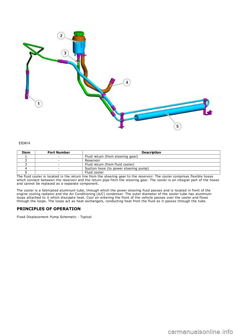
ItemPart NumberDescription
1-Fluid ret urn (from s t eering gear)2-Reservoi r
3-Fluid ret urn (from flui d cool er)
4-Suct ion hos e (to power s t eering pump)5-Fluid cooler
The fl uid cooler is locat ed i n t he ret urn l ine from the st eeri ng gear t o t he res ervoir. The cool er compri s es fl exi bl e hos eswhich connect between t he res ervoi r and the return pipe from the st eeri ng gear. The cooler i s an i nt egral part of t he hos esand cannot be repl aced as a s eparat e component .
The cool er is a fabri cat ed alumi num t ube, t hrough which t he power st eering fl ui d passes and i s located in front of theengi ne cool ing radiator and t he Air Condit ioning (A/C) condens er. The out er di ameter of the cooler t ube has aluminumloops at tached to it which di ss i pat e heat. Cool air entering t he front of t he vehicle pas s es over t he cool er and flowst hrough the l oops . The l oops act as heat exchangers , conducti ng heat from t he fl uid as it pass es t hrough t he tube.
PRINCIPLES OF OPERATION
Fixed Dis placement Pump Schemat ic - Typical
Page 1247 of 3229
SymptomPossible CauseAction
Di fficul t t o s tart aft er hots oak (vehicle st andi ng,engine off, aft er engi ne hasreached operati ngt emperature)
Injector leakElectronic engine controlsFuel pumpExhaus t gas recircul ati on val ves tuck open
Check fuel and engine control sys tems for DTCs andrefer t o t he rel evant DTC Index
Engine cranks t oo fas t/s lowBatt eryCompres s ions high/lowSt arti ng s yst em
Check batt ery is fully charged and in s ervi ceablecondit ion. Check engine compres s ions . Checkint egrit y of s tart ing sys tem
Driveability
Rough idl eLow/contami nat ed fuelFuel s ys temAir i ntake s yst emElectronic engine controls
Check fuel l evel /condi ti on. Check for DTCs and referto relevant DTC Index. Check i ntegri ty of fuel, airint ake, and engi ne s yst ems
Engine i dl e s peed high, low,errati cAir i ntake s yst emExces s ive blow-byExhaus t gas recircul ati on val veTurbo charger bearing/sealElectronic engine controls
Check for DTCs and refer t o t he rel evant DTC Index.Check i nt egri ty of ai r intake, Turbo charger, andengi ne s ys t ems
Lack of power underaccel erati onContami nat ed fuelAir i ntake s yst emBlocked exhaus t/cat alyt icconverterTurbo changer faul tFuel s ys temElectronic engine controlsLow engine compres s ions
Check for fuel cont aminati on. Check for DTCs andrefer t o relevant DTC Index. Check int egrit y of airint ake, exhaus t, Turbo charger, and engi ne s ys t ems
Engine s t ops /st all sContami nat ed fuelFuel s ys temAir i ntake s yst emElectronic engine controls
Check for fuel cont aminati on. Check for DTCs andrefer t o t he rel evant DTC Index. Check int egrit y offuel, ai r intake, and engi ne s ys t ems
Diesel Particulate Filter (DPF) Warning Messages
'DPF Ful l Vi s it Dealer'mes s age dis played. Torquederat e, regenerati on lockedout (DTC P200200 als ol ogged)
Part iculat e fi lt er soot mas squant it y above maximumt hres hol dCAUTION: All i nt ake air s yst em leaks MUST berecti fi ed before carrying out dynamic regenerat ion.
Check for and recti fy any related DTCs . Check forcorrect ins tal lati on and int egrit y of i nt ake airsys t em, recti fy as requi red. Carry out dynami cregenerati on usi ng t he manufacturer approveddiagnos t ic s yst em
'Reduced Engi nePerformance' mes s agedis played. No effect t odri veabi lit y. Regenerat ionreduced t o lower level (2)(DTC P054516 al so logged)
Pre-cat alyt ic convertert emperature s ens or circui tvolt age bel ow t hres hol d
Refer to elect rical circui t diagrams and checkpre-cat al yti c convert er temperat ure s ens or ci rcuitfor s hort t o ground or open ci rcuit
'Reduced Engi nePerformance' mes s agedis played. No effect t odri veabi lit y (DTC P222700als o l ogged)
At mospheri c pres s ure s ens ordefecti veClear DTC, run engine for 2 mi nut es, s et igni ti onst atus to O FF (power down), run engine for further2 mi nut es , set i gni ti on s tat us to OFF (power down),set i gni ti on s tat us to ON and read DTCs. If DTC s t illpres ent refer t o new module/component ins tal lati onnot e at t he t op of the DTC Index
'Reduced Engi nePerformance' or 'EngineSyst em Fault ' mes sagedis played. Torque derate,regenerat ion l ocked out(DTC P244A16 al so logged)
Part iculat e fi lt er different ialpres s ure bel ow li mitClear DTC, cycle i gni ti on s tat us from ON t o OFF(power down) a mi ni mum of s i x ti mes , set i gni ti onst atus to O N, if DTC remains i ns t all a newdifferent ial pres sure s ens or
'DPF Ful l Vi s it Dealer'mes s age dis played. Torquederat e, regenerati on lockedout (DTC P244B68 als ol ogged)
Part iculat e fi lt er different ialpres s ure hi gh - engi ne prot ect ionacti veCAUTION: All i nt ake air s yst em leaks MUST berecti fi ed before carrying out dynamic regenerat ion.
Check for correct ins tall ati on and int egrit y ofdifferent ial pres sure s ens or hoses , rect ify asrequired. Check for correct i ns t allat ion and i ntegri tyof intake ai r sys tem, rect ify as requi red. Carry outdynami c regenerati on us ing t he manufacturerapproved di agnos ti c s ys t em'Reduced Engi nePerformance' or 'EngineSyst em Fault ' mes sagedis played. Torque derate,regenerat ion l ocked out(DTC P244C00 al so logged)
Downs tream catalyt ic convertert emperature s ens or volt agebelow lower li mitSensor failure
Refer to the el ect ri cal circui t diagrams and checkdowns t ream cat al yti c convert er temperat ure sens orci rcuit for open ci rcuit . Ins tal l new temperat uresens or as required
Page 1637 of 3229
Blower mot orHeater coreCabin ai r fil ter.For addit ional informat ion, refer t o: Air Di st ri buti on and Fi lt eri ng (412-01 Climat e Cont rol, Des cript ion andOperat ion).A/C evaporat or.For addit ional informat ion, refer t o: Air Condit ioning (412-01 Cli mat e Cont rol , Descripti on and Operat ion).Air i ntake flap and s tepper motor.For addit ional informat ion, refer t o: Cont rol Component s (412-01 Cli mat e Cont rol , Descripti on and Operat ion).Air di st ri but ion fl aps and s t epper mot ors .For addit ional informat ion, refer t o: Cont rol Component s (412-01 Cli mat e Cont rol , Descripti on and Operat ion).Temperature blend flaps and s t epper mot ors .For addit ional informat ion, refer t o: Cont rol Component s (412-01 Cli mat e Cont rol , Descripti on and Operat ion).Electric boos ter heater (if fi tt ed).For addit ional informat ion, refer t o: Electric Boos ter Heater (412-02 Auxi li ary Cl imat e Control, Des cript ion andOperat ion).
Blower Motor
The blower mot or compris es an open hub, centrifugal fan powered by an elect ric motor. Operati on of the bl ower motor iscont rol led by t he ATC module in conjuncti on wit h t he blower mot or control modul e. The ATC module provi des a Puls e W i dthModulated (PW M) si gnal t o t he blower motor control modul e based on the requi red bl ower speed. The bl ower motor cont rolmodule i nterprets the PW M s ignal as a blower mot or speed and controls t he volt age to t he blower mot or accordingl y.For addit ional informat ion, refer t o: Cont rol Component s (412-01 Cli mat e Cont rol , Descripti on and Operat ion).
Heater Core
The heat er core provi des t he heat s ource to warm the ai r bei ng s uppl ied i nto t he cabin. The heat er core is an alumi num, 2pass , fin and t ube heat exchanger ins t al led acros s t he widt h of t he heat er ass embly. Two al uminum tubes att ached t o t heheat er core extend t hrough t he engi ne bulkhead and connect t o t he engine cool ing s ystem. W hen the engine is runni ng,engi ne cool ant is const antl y ci rculat ed through the heater core by the coolant pump. For addit ional informati on, refer t o:
Engi ne Cool ing (303-03A Engine Cooli ng - I6 3.2L Petrol, Des cript ion and Operat ion),Engi ne Cool ing (303-03B Engine Cooli ng - TD4 2.2L Di esel , Descri pti on and Operat ion).
VENTILATION OUTLETS
The vent il ati on out let s all ow t he free flow of ai r through t he cabi n. The out let s are ins tall ed in the LH and RH rear quart erpanel s, behind the t ail lamps .
Each vent ilat ion out let compri ses a gril le covered by a s oft rubber fl ap, and i s effect ively a non-ret urn val ve. The flapsopen and cl ose aut omat ical ly depending on t he different ial between cabin and out si de air pres s ures .
PRINCIPLES OF OPERATION
Operat ion of t he heat ing and venti lat ion s ys tem is controlled by the ATC modul e.For addit ional informat ion, refer t o: Cont rol Component s (412-01 Cli mat e Cont rol , Descripti on and Operat ion).
Page 1640 of 3229
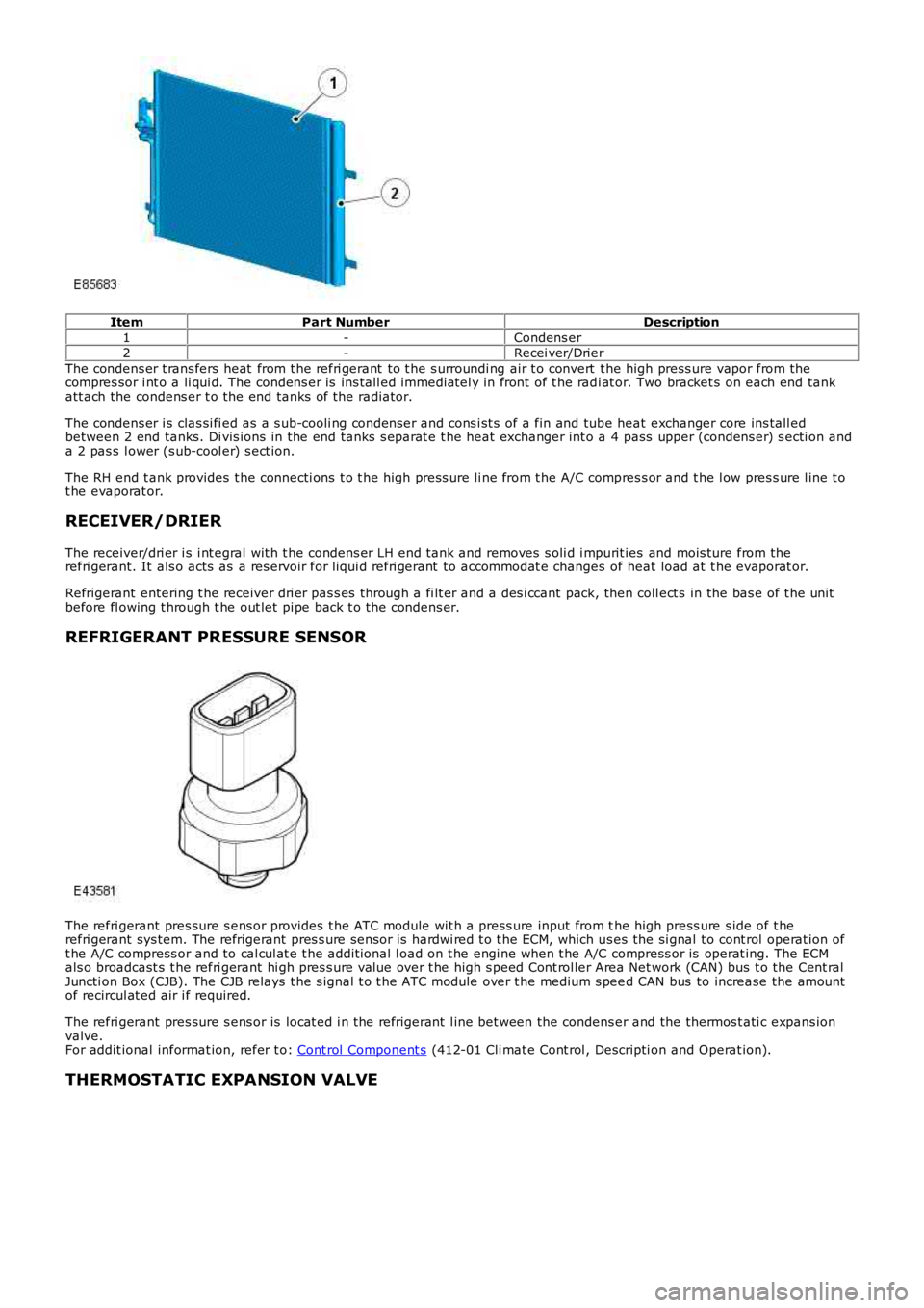
ItemPart NumberDescription
1-Condens er2-Recei ver/Drier
The condens er t rans fers heat from t he refri gerant to t he s urroundi ng air t o convert t he high press ure vapor from thecompres sor i nt o a li qui d. The condens er is ins tall ed immediatel y in front of t he radi at or. Two bracket s on each end tankatt ach the condens er t o the end tanks of the radiator.
The condens er i s clas si fi ed as a s ub-cooli ng condenser and cons i st s of a fin and tube heat exchanger core ins tall edbetween 2 end tanks. Di vis ions in the end tanks s eparat e t he heat exchanger int o a 4 pass upper (condens er) s ecti on anda 2 pas s l ower (s ub-cool er) s ect ion.
The RH end t ank provides t he connecti ons t o t he high press ure li ne from t he A/C compres s or and t he l ow pres s ure l ine t ot he evaporat or.
RECEIVER/DRIER
The receiver/dri er i s i nt egral wit h t he condens er LH end tank and removes s oli d i mpurit ies and mois ture from therefri gerant. It als o acts as a res ervoir for liqui d refri gerant to accommodat e changes of heat load at t he evaporat or.
Refrigerant entering t he receiver dri er pas s es through a fi lt er and a des i ccant pack, then coll ect s in the bas e of t he unitbefore fl owing t hrough t he out let pi pe back t o t he condens er.
REFRIGERANT PRESSURE SENSOR
The refri gerant pres sure s ens or provides t he ATC module wit h a press ure input from the high press ure s ide of t herefri gerant sys tem. The refrigerant pres s ure sens or is hardwi red t o t he ECM, which us es the si gnal t o cont rol operat ion oft he A/C compress or and to cal cul at e t he addit ional l oad on t he engi ne when t he A/C compress or is operat ing. The ECMals o broadcast s t he refri gerant hi gh pres s ure value over t he high s peed Cont rol ler Area Net work (CAN) bus t o the Cent ralJuncti on Box (CJB). The CJB relays t he s ignal t o t he ATC module over t he medium s peed CAN bus to increase the amountof recircul at ed air i f required.
The refri gerant pres sure s ens or is locat ed i n the refrigerant l ine bet ween the condens er and the thermos t ati c expans ionvalve.For addit ional informat ion, refer t o: Cont rol Component s (412-01 Cli mat e Cont rol , Descripti on and Operat ion).
THERMOSTATIC EXPANSION VALVE
Page 1737 of 3229
Publi shed: 26-Jul-2011
Auxiliary Heating - Fuel Fired Booster Heater
Diagnosi s and Tes ti ng
Overview
For informati on on t he des cri pti on and operati on of the s ys tem, refer t o s ect ion 412-02 -REFER to:
Fuel Fired Boos t er Heat er (412-02B Auxil iary Cli mate Cont rol, Des cri pt ion and Operati on),Fuel Fired Boos t er Heat er (412-02B, Des cript ion and Operat ion),Fuel Fired Boos t er Heat er (412-02B Auxil iary Cli mate Cont rol, Removal and Ins t al lat ion),Fuel Fired Boos t er Heat er Fuel Pump (412-02B Auxili ary Cl imat e Control, Removal and Ins tall ati on),Fuel Fired Boos t er Heat er Cool ant Pump (412-02B Auxil iary Cli mate Cont rol, Removal and Ins t al lat ion),Fuel Fired Boos t er Heat er Glow Pl ug And Burner As sembl y (412-02B Auxi liary Cli mate Cont rol , Removal andIns tal lat ion).Auxi li ary Heat ing i n the works hop manual .
Inspection and Verification
1. Verify t he cus t omer concern.1.
2. Vis ually ins pect for obvious mechani cal or electrical fault s .2.
Visual inspectionMechanicalElectrical
Fuel fired heater as sembl y- Combus ti on air fan- Coolant inl et /out let- Heat exchanger- Temperat ure s ens or- Exhaus t- Fuel inlet- Ai r inlet- EvaporatorAuxili ary fuel pump and li nesAuxili ary coolant pump
Fus esHarness esEl ect ri cal connector(s )Cont roll er area network (CAN) ci rcuit sCont rol module(s)
3. If an obvious cause for an obs erved or report ed concern is found, correct t he caus e (if pos s ible) beforeproceeding t o t he next s t ep3.
4. Us e the approved di agnos ti c s ys t em or a s can t ool t o ret rieve any diagnos t ic t rouble codes (DTCs ) before movingont o t he sympt om chart or DTC i ndex.4.
CAUTION: Di agnos is by s ubs ti tut ion from a donor vehicle is NO T acceptabl e. Subs ti tut ion of cont rol modules doesnot guarant ee confirmat ion of a faul t, and may als o caus e addit ional fault s i n t he vehi cl e being t est ed and/or t he donorvehi cl e.
• NOTE: If the control modul e or a component i s s us pect and the vehicle remains under manufacturer warrant y, refer t o theW arranty Pol icy and Procedures manual (s ect ion B1.2), or determine i f any pri or approval programme is in operat ion, pri ort o the ins tall ati on of a new module/component.
• NOTE: Generic scan t ool s may not read the codes li st ed, or may read only 5-digi t codes . Match t he 5 digi ts from t he s cant ool t o t he fi rs t 5 di gi ts of the 7-digit code li s ted t o i dent ify the fault (the last 2 digi ts gi ve ext ra informati on read by themanufacturer-approved di agnos ti c s ys t em).
• NOTE: Check and recti fy bas ic faul ts before beginni ng diagnos t ic rout ines i nvol vi ng pinpoint t es t s.
• NOTE: Ins pect connect ors for s igns of water ingres s , and pins for damage and/or corros ion.
• NOTE: If DTCs are recorded and, aft er performi ng the pi npoi nt tes ts , a fault is not present , an int ermi tt ent concern maybe t he caus e. Always check for loose connect ions and corroded terminals .
The t abl e below l is t s all Diagnos ti c Trouble Codes (DTCs ) t hat could be logged in the Fuel Fi red Boos ter Heater Module, foraddi ti onal Di agnos is and Tes ti ng informat ion refer t o t he relevant Diagnosi s and Test ing Secti on
DTC index
For a compl ete lis t of all Di agnos ti c Trouble Codes (DTCs) t hat could be logged on this vehicle, pleas e refer to Sect ion100-00. REFER t o: Diagnost ic Troubl e Code (DTC) Index - DTC: Auxi li ary Heater Control Modul e (AHCM) (100-00 GeneralInformat ion, Des cript ion and Operat ion).
Page 1744 of 3229
The s olenoi d coil of the auxil iary fuel pump i s ins tal led around a hous ing which cont ains a pl unger and pis t on. The pi st onlocates i n a bus h, and a s pri ng is i nst all ed on t he pis ton bet ween the bus h and t he plunger. A fil ter i nsert and a fuel l ineconnector are ins tal led i n the inlet end of t he hous ing. A non return valve and a fuel line connect or are i nst all ed in the fueloutl et end of t he housi ng.
W hi le t he s olenoid coil i s de-energized, the spring holds t he pis t on and plunger i n t he clos ed pos i ti on at the i nlet end oft he hous ing. An O-ri ng s eal on the pl unger provides a fuel ti ght s eal bet ween t he plunger and t he filt er ins ert , prevent ingany fl ow t hrough t he pump. W hen the sol enoi d coi l is energi zed, t he pis ton and pl unger move t owards t he outl et end oft he hous ing, unti l the pl unger cont act s t he bush; fuel i s t hen drawn i n t hrough the i nlet connecti on and fi lt er. The i ni ti almovement of t he pis t on als o clos es t rans verse dril li ngs in t he bus h and is olat es the pumpi ng chamber at t he out let end oft he hous ing. Subsequent movement of t he pis ton then forces fuel from t he pumping chamber through t he non return val veand int o t he li ne to the fuel fi red boost er heat er. W hen the s olenoid de-energizes , the s pri ng moves the pi s ton andplunger back t owards t he cl osed pos it ion. As t he pis t on and plunger move towards t he clos ed posi ti on, fuel fl ows pas t t heplunger and through t he annul ar gaps and t rans vers e holes i n t he bus h t o replenis h the pumping chamber.
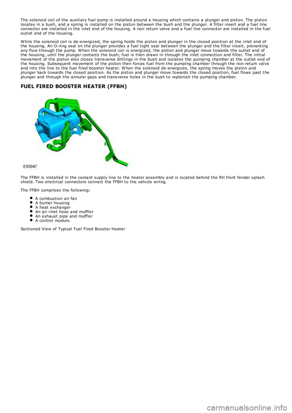
FUEL FIRED BOOSTER HEATER (FFBH)
The FFBH is ins tall ed in the coolant s uppl y li ne to the heat er as s embly and i s located behind the RH front fender s plas hs hield. Two el ect ri cal connectors connect the FFBH t o t he vehi cl e wi ri ng.
The FFBH compris es t he fol lowing:
A combus ti on air fanA burner housi ngA heat exchangerAn air i nlet hose and mufflerAn exhaus t pipe and mufflerA control modul e.
Sect ioned View of Typi cal Fuel Fired Boost er Heater
Page 1745 of 3229
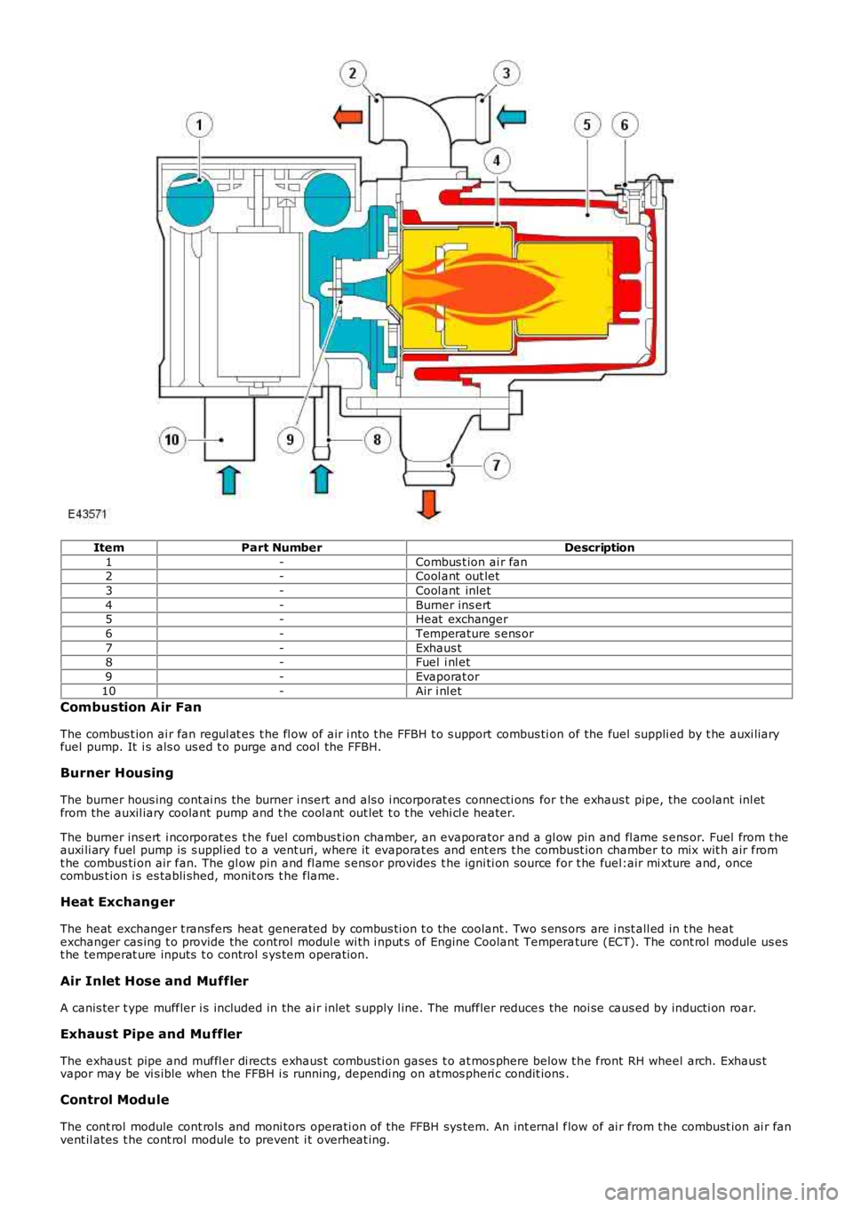
ItemPart NumberDescription
1-Combus t ion ai r fan2-Cool ant out let
3-Cool ant inlet
4-Burner ins ert5-Heat exchanger
6-Temperature s ens or
7-Exhaus t8-Fuel i nl et
9-Evaporat or
10-Air i nl et
Combustion Air Fan
The combus t ion ai r fan regul at es t he fl ow of air i nto t he FFBH t o s upport combus ti on of the fuel suppli ed by t he auxi liaryfuel pump. It i s als o us ed t o purge and cool the FFBH.
Burner Housing
The burner hous ing cont ai ns the burner i nsert and als o i ncorporat es connecti ons for t he exhaus t pipe, the coolant inl etfrom the auxil iary coolant pump and t he cool ant out let t o t he vehi cl e heater.
The burner ins ert i ncorporat es t he fuel combus t ion chamber, an evaporator and a gl ow pin and fl ame s ens or. Fuel from t heauxi li ary fuel pump is s uppl ied t o a vent uri, where it evaporat es and ent ers t he combust ion chamber to mix wit h air fromt he combus ti on air fan. The gl ow pin and fl ame s ens or provides t he igni ti on source for t he fuel:air mi xture and, oncecombus t ion i s es tabli shed, monit ors t he flame.
Heat Exchang er
The heat exchanger t ransfers heat generated by combus ti on t o the coolant . Two s ens ors are i nst all ed in t he heatexchanger cas ing t o provide the control modul e wi th i nput s of Engine Coolant Temperature (ECT). The cont rol module us est he temperat ure inputs t o control s ys tem operati on.
Air Inlet Hose and Muffler
A canis ter t ype muffler i s included in the ai r inlet s upply l ine. The muffler reduces the noi se caus ed by inducti on roar.
Exhaust Pipe and Muffler
The exhaus t pipe and muffl er di rects exhaus t combus ti on gases t o at mos phere below t he front RH wheel arch. Exhaus tvapor may be vi s ible when the FFBH i s running, dependi ng on atmos pheri c condit ions .
Control Module
The cont rol module cont rols and moni tors operati on of the FFBH sys tem. An int ernal flow of ai r from t he combust ion ai r fanvent il ates t he cont rol module to prevent i t overheat ing.
Page 1752 of 3229
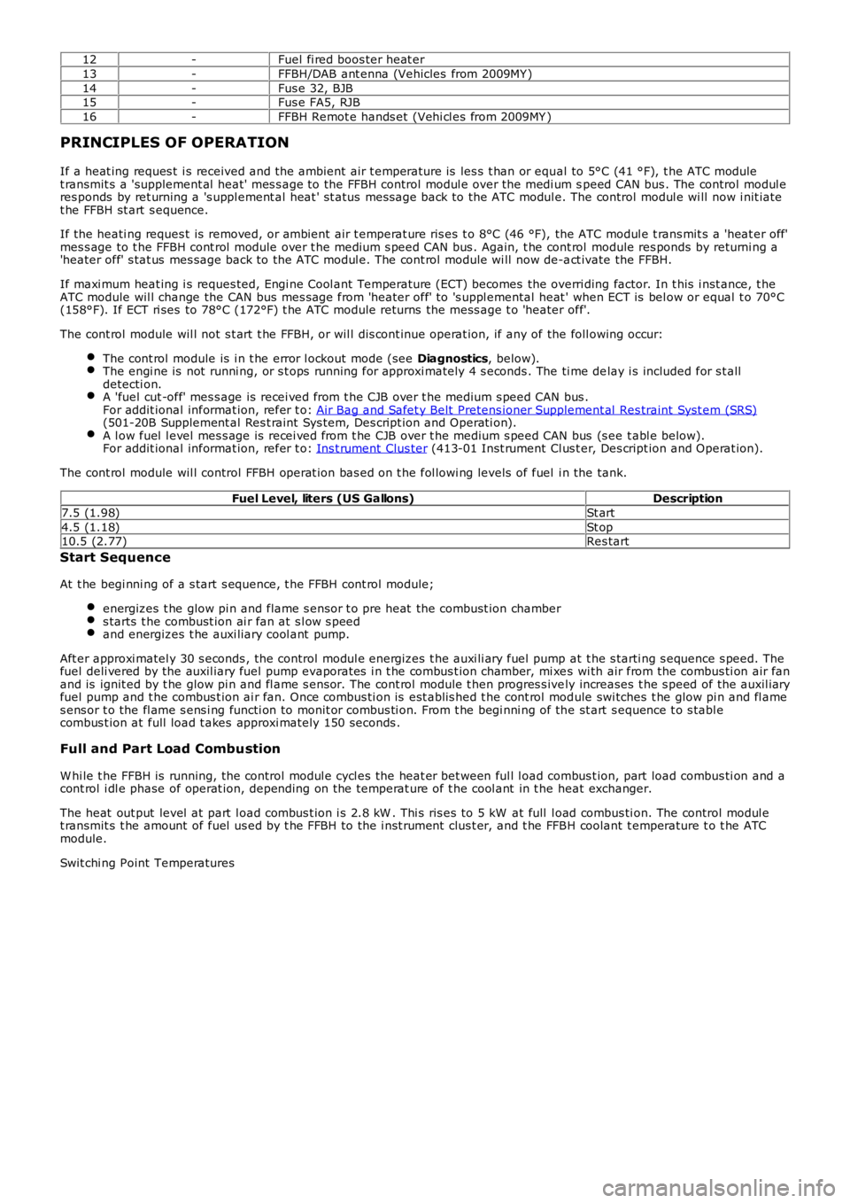
12-Fuel fi red boos ter heat er
13-FFBH/DAB ant enna (Vehicles from 2009MY )
14-Fus e 32, BJB15-Fus e FA5, RJB
16-FFBH Remot e hands et (Vehi cl es from 2009MY )
PRINCIPLES OF OPERATION
If a heat ing reques t i s received and t he ambient air t emperature is les s t han or equal to 5°C (41 °F), t he ATC modulet ransmit s a 'supplement al heat' mes s age to the FFBH control modul e over the medi um speed CAN bus . The control modul eres ponds by ret urning a 's uppl ement al heat ' st atus mess age back to the ATC modul e. The control modul e wi ll now i nit iatet he FFBH st art s equence.
If the heati ng reques t is removed, or ambient air t emperat ure ris es t o 8°C (46 °F), the ATC modul e t rans mit s a 'heat er off'mes s age to t he FFBH cont rol module over t he medium s peed CAN bus . Again, t he cont rol module res ponds by returni ng a'heater off' s tat us mes sage back to the ATC modul e. The cont rol module wi ll now de-act ivate the FFBH.
If maxi mum heat ing i s reques ted, Engi ne Cool ant Temperature (ECT) becomes the overriding factor. In t his i nst ance, t heATC module wil l change the CAN bus mes sage from 'heater off' to 's uppl emental heat ' when ECT is bel ow or equal t o 70°C(158°F). If ECT ri ses to 78°C (172°F) t he ATC module returns the mess age t o 'heater off'.
The cont rol module wil l not s t art t he FFBH, or wil l dis cont inue operat ion, if any of the foll owing occur:
The cont rol module is i n t he error l ockout mode (see Diagnostics, below).The engi ne is not runni ng, or s t ops running for approxi mately 4 s econds . The ti me delay i s included for s t alldetecti on.A 'fuel cut -off' mes s age is recei ved from t he CJB over t he medium s peed CAN bus .For addit ional informat ion, refer t o: Air Bag and Safet y Belt Pretens ioner Supplement al Res traint Syst em (SRS)(501-20B Supplement al Res t raint Sys tem, Des cript ion and O perati on).A l ow fuel l evel mes s age is recei ved from t he CJB over t he medium s peed CAN bus (s ee t abl e below).For addit ional informat ion, refer t o: Ins t rument Clus ter (413-01 Inst rument Cl us t er, Des cript ion and Operat ion).
The cont rol module wil l control FFBH operat ion bas ed on t he fol lowi ng levels of fuel i n the tank.
Fuel Level, liters (US Gallons)Description
7.5 (1.98)St art
4.5 (1.18)St op10.5 (2.77)Res tart
Start Sequence
At t he begi nni ng of a s tart s equence, t he FFBH cont rol module;
energizes t he glow pi n and flame s ens or t o pre heat the combust ion chambers tarts t he combust ion ai r fan at s l ow s peedand energizes t he auxi liary cool ant pump.
Aft er approxi matel y 30 s econds , the control modul e energizes t he auxi li ary fuel pump at t he s tarti ng s equence s peed. Thefuel deli vered by the auxil iary fuel pump evaporates i n t he combus t ion chamber, mi xes wi th air from the combus ti on air fanand is ignit ed by t he glow pi n and fl ame s ensor. The cont rol module t hen progres s ively increases t he s peed of the auxil iaryfuel pump and t he combus t ion ai r fan. Once combus ti on is est ablis hed t he cont rol module swi tches t he glow pi n and fl ames ens or t o the fl ame s ens i ng functi on to monit or combus ti on. From t he begi nni ng of the st art s equence t o s tabl ecombus t ion at full load t akes approxi mately 150 seconds .
Full and Part Load Combustion
W hi le t he FFBH is running, the control modul e cycl es the heat er bet ween ful l l oad combus t ion, part load combus ti on and acont rol i dl e phase of operat ion, depending on the temperat ure of t he cool ant in t he heat exchanger.
The heat out put level at part l oad combus t ion i s 2.8 kW . Thi s ris es to 5 kW at full l oad combus ti on. The control modul et ransmit s t he amount of fuel us ed by t he FFBH to the i nst rument clus t er, and t he FFBH coolant t emperature t o t he ATCmodule.
Swit chi ng Point Temperatures
Page 1754 of 3229
s tart fail ure or flameout, and decreas ed by one if a subs equent s tart is succes s ful . If t he event t imer i ncreas es t ot hree (over any number of drive cycl es), the cont rol module ent ers t he error lockout mode.Heat exchanger casing overheat: To prot ect t he s ys t em from exces s ive t emperatures , t he cont rol module ent erst he error l ockout mode if t he heat exchanger coolant temperat ure exceeds 125 °C (257 °F).Battery voltage out of limits: Error lockout wi ll occur if bat tery vol tage fall s bel ow 10.25 or ris es above 15.5 volt s .
The error lockout mode can be cleared usi ng the Land Rover approved di agnos ti c s ys t em, or by dis connect ing the bat terypower supply for a mi nimum of 10 s econds.
Remote Operation - Vehicles from 2009MY with FFBH Remote Control
The 868.3 MHz Radi o Frequency (RF) si gnal s t ransmit ted by the remote hands et are recei ved by the DAB/FFBH ant ennalocated i n t he LH rear s i de window. The s ignal s received by t he antenna are detected by t he FFBH receiver. A 'handshake's ignal is s ent back from the recei ver t o t he hands et t o confirm a val id on or off reques t and act ivate the handset LEDaccordi ngl y. The recei ver proces s es the s i gnal it recei ved and trans mi ts the appropriate si gnal s via a dedi cat ed bus t o theFFBH cont rol module.
• NOTE: The ‘handshake’ si gnal only confi rms hands et-receiver communi cat ions were s uccess ful , and not that t he FFBH hast urned on.
W hen t he FFBH is act ivated by the remote hands et, t he FFBH cont rol module will al low t he FFBH t o operate for 30 minutesor unt il an off request is received from t he remot e hands et or CJB. During t he 30 minut e period, the FFBH may operat e i neit her full l oad combus ti on, part load combus t ion or a controll ed idle phas e of operat ion, depending on t he t emperature oft he coolant i n t he heat exchanger.
Pre-burn Thresholds
The FFBH unit wi ll only acti vat e remotely if t he fol lowing thres hold condit ions are met:
Pre-burn batt ery vol tage check: ≥11.5V (volt age at FFBH terminals )Pre-burn coolant temperat ure check: ≤15°C (int ernal FFBH measurement )Pre-burn fuel l evel check: ≥7.5 lit ers (value s t ored i n FFBH at ignit ion off)
The fuel level val ue s tored wit hin t he FFBH unit i s only updated when t he engine i s running. W hen s t art ing t he FFBH viaremot e control wit h the engi ne off, the fuel l evel value us ed in the FFBH calculat ions wi ll be t hat s t ored at t he las t key offevent . It i s t herefore poss ibl e for t he FFBH t o fai l to operat e remotel y if t he engine was s t opped wi th a low fuel level; i ft he fuel tank i s s ubs equent ly refuell ed, the FFBH s t ored fuel l evel wil l st il l read l ow i f the engine has not been s tarteds ince refuel li ng.
If the FFBH does not act ivate due to low bat tery vol tage or l ow fuel l evel, t he FFBH cont rol module transmit s a mes s age ispass ed on t he medi um and high speed CAN bus es, vi a t he CJB to the i nst rument clus ter mes s age cent er which wil l dis playone of the foll owing mes s ages at i gnit ion on:
AUXILIARY HEATER UNAVAILABLE LOW FUELAUXILIARY HEATER UNAVAILABLE LOW BATTERY .
If bot h l ow fuel and low batt ery volt age mes sages are val id, t he ins trument cl ust er mes sage center wi ll alt ernate bet weent he two mes sages .
Remote Control ‘Park Heat’ to ATC ‘Supplementary Heat’ Transitions
• NOTE: The FFBH can s ti ll be acti vat ed by t he ATC module as previ ous l y descri bed
If the FFBH has been operated remot el y (‘park heat’) and the vehicl e is st art ed whilst the FFBH i s s ti ll act ive, it willt ransi ti on int o t he ATC-control led ‘s upplement ary heat’ mode if t he ATC request s i t.
Shoul d t he ATC t hen send a mess age t o t he FFBH to turn off, the FFBH will remain active if 30 minut es has not yetelaps ed from t he ori ginal remot e cont rol ‘park heat ’ request . Once t he remai nder of 30 mi nut es has elaps ed, t he FFBH wil lt urn off.
Swit chi ng Point Temperatures
W hen remotel y s tarted t he FFBH us es a different s et of s wit chi ng poi nt temperat ures t o t he normal ‘supplement al heat’mode. Thi s is because the remot e s tart feature can s tart the FFBH wi th the engine off – t hus different t hres hol ds arerequired t o opti mis e t he heati ng of the engine coolant.
Swit chi ng Point Temperatures
Page 1870 of 3229
ClockAntenna powerLight Emit t ing Di ode (LED) il lumi nat ion.
In transi t mode t he CAN port and t he ON/OFF s wit ch are t he only ci rcuit s that are left act ive.
The CAN port is l eft open to allow the EXIT from transi t mode s ignal to be received. The O N/OFF s wit ch is left act ive t oall ow feedback to the driver vi a t he head uni t LCD (liqui d crys tal dis play), t hat the unit is i n t ransi t mode s houl d t he dri veratt empt t o power up the head unit . This wi ll only occur when t he vehicle engine is runni ng and the bat tery is above 12.3Volt s.
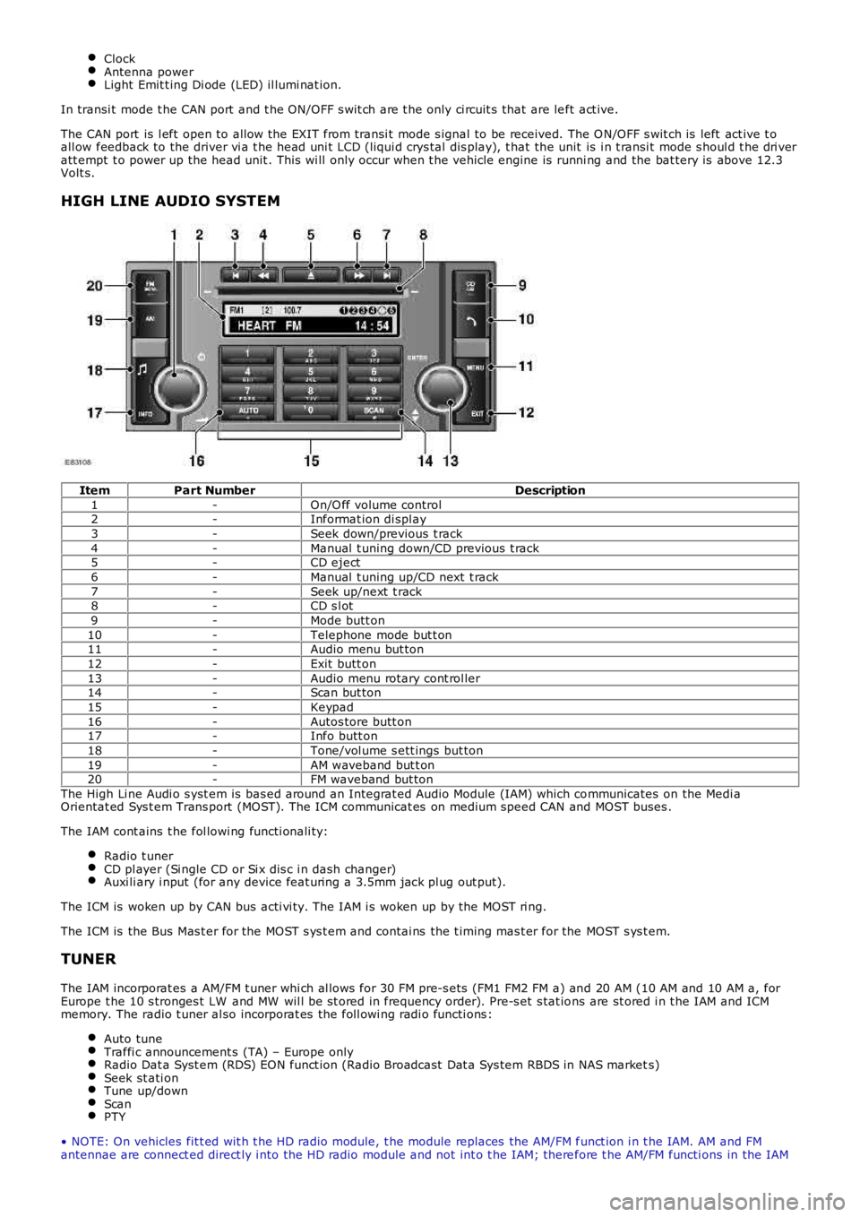
HIGH LINE AUDIO SYSTEM
ItemPart NumberDescription
1-On/O ff volume control2-Informat ion di spl ay
3-Seek down/previous t rack
4-Manual t uning down/CD previous t rack5-CD eject
6-Manual t uning up/CD next t rack
7-Seek up/next t rack8-CD s l ot
9-Mode butt on
10-Telephone mode but t on11-Audio menu but ton
12-Exit butt on
13-Audio menu rotary cont rol ler14-Scan but ton
15-Keypad
16-Autos tore butt on17-Info butt on
18-Tone/vol ume s ett ings but ton
19-AM waveband but t on20-FM waveband but ton
The High Li ne Audi o s yst em is bas ed around an Integrat ed Audio Module (IAM) which communicates on the Medi aOrientat ed Sys t em Trans port (MOST). The ICM communicat es on medium speed CAN and MOST buses .
The IAM cont ains t he fol lowi ng functi onali ty:
Radio t unerCD pl ayer (Si ngle CD or Si x dis c i n dash changer)Auxi li ary i nput (for any device feat uring a 3.5mm jack pl ug out put).
The ICM is woken up by CAN bus acti vi ty. The IAM i s woken up by the MOST ri ng.
The ICM is the Bus Mas t er for the MOST s ys t em and contai ns the t iming mas t er for the MOST s ys t em.
TUNER
The IAM incorporat es a AM/FM t uner whi ch al lows for 30 FM pre-s ets (FM1 FM2 FM a) and 20 AM (10 AM and 10 AM a, forEurope t he 10 s tronges t LW and MW wil l be st ored in frequency order). Pre-s et s tat ions are st ored i n t he IAM and ICMmemory. The radio t uner al so incorporat es the foll owi ng radi o functi ons :
Auto tuneTraffi c announcement s (TA) – Europe onlyRadio Dat a Syst em (RDS) EON funct ion (Radio Broadcast Dat a Sys tem RBDS in NAS markets)Seek st ati onTune up/downScanPTY
• NOTE: On vehicles fit t ed wit h t he HD radio module, t he module replaces the AM/FM funct ion i n t he IAM. AM and FMantennae are connect ed direct ly i nto the HD radio module and not int o t he IAM; therefore t he AM/FM functi ons in the IAM