diagram LAND ROVER FRELANDER 2 2006 Repair Manual
[x] Cancel search | Manufacturer: LAND ROVER, Model Year: 2006, Model line: FRELANDER 2, Model: LAND ROVER FRELANDER 2 2006Pages: 3229, PDF Size: 78.5 MB
Page 48 of 3229
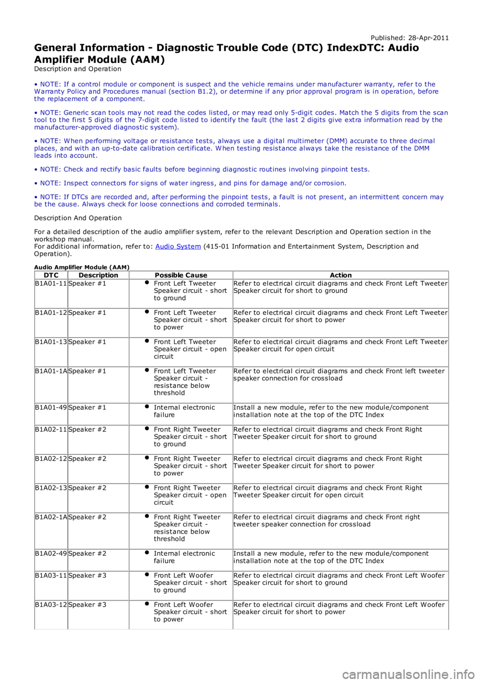
Publ is hed: 28-Apr-2011
General Information - Diagnostic Trouble Code (DTC) IndexDTC: Audio
Amplifier Module (AAM)
Des cript ion and Operat ion
• NOTE: If a cont rol module or component i s s uspect and the vehicl e remai ns under manufacturer warrant y, refer t o t heW arranty Pol icy and Procedures manual (s ect ion B1.2), or determine i f any pri or approval program is i n operat ion, beforet he replacement of a component.
• NOTE: Generic scan t ool s may not read the codes li st ed, or may read only 5-digi t codes . Match t he 5 digi ts from t he s cant ool t o t he fi rs t 5 di gi ts of the 7-digit code li s ted t o i dent ify the fault (the last 2 digi ts gi ve ext ra informati on read by themanufacturer-approved di agnos ti c s ys t em).
• NOTE: W hen performing volt age or res is t ance t est s , always use a digi tal mult imeter (DMM) accurat e t o t hree deci malplaces, and wi th an up-t o-date cal ibrat ion cert ificate. W hen tes ti ng res is t ance al ways take t he res is t ance of t he DMMleads i nt o account .
• NOTE: Check and recti fy bas ic faul ts before beginni ng diagnos t ic rout ines i nvol vi ng pinpoint t es t s.
• NOTE: Ins pect connect ors for s igns of water ingres s , and pins for damage and/or corros ion.
• NOTE: If DTCs are recorded and, aft er performi ng the pi npoi nt tes ts , a fault is not present , an int ermi tt ent concern maybe t he caus e. Always check for loose connect ions and corroded terminals .
Des cript ion And Operat ion
For a detail ed descripti on of the audio ampli fier s ys tem, refer to the relevant Des cri pti on and Operati on s ect ion i n t heworks hop manual .For addit ional informat ion, refer t o: Audi o Sys tem (415-01 Informati on and Entertainment Sys tem, Des cript ion andOperat ion).
Audio Amplifier Module (AAM)
DT CDescriptionPossible CauseAction
B1A01-11Speaker #1Front Left TweeterSpeaker ci rcuit - s hortto ground
Refer to el ect ri cal circui t diagrams and check Front Left Tweet erSpeaker circui t for s hort t o ground
B1A01-12Speaker #1Front Left TweeterSpeaker ci rcuit - s hortto power
Refer to el ect ri cal circui t diagrams and check Front Left Tweet erSpeaker circui t for s hort t o power
B1A01-13Speaker #1Front Left TweeterSpeaker ci rcuit - opencircuit
Refer to el ect ri cal circui t diagrams and check Front Left Tweet erSpeaker circui t for open circui t
B1A01-1ASpeaker #1Front Left TweeterSpeaker ci rcuit -res is t ance belowthreshold
Refer to el ect ri cal circui t diagrams and check Front left tweeters peaker connect ion for cros s load
B1A01-49Speaker #1Int ernal electroni cfai lureIns tall a new module, refer to the new modul e/componenti nst all ati on not e at t he t op of the DTC Index
B1A02-11Speaker #2Front Right TweeterSpeaker ci rcuit - s hortto ground
Refer to el ect ri cal circui t diagrams and check Front RightTweet er Speaker circui t for s hort t o ground
B1A02-12Speaker #2Front Right TweeterSpeaker ci rcuit - s hortto power
Refer to el ect ri cal circui t diagrams and check Front RightTweet er Speaker circui t for s hort t o power
B1A02-13Speaker #2Front Right TweeterSpeaker ci rcuit - opencircuit
Refer to el ect ri cal circui t diagrams and check Front RightTweet er Speaker circui t for open circui t
B1A02-1ASpeaker #2Front Right TweeterSpeaker ci rcuit -res is t ance belowthreshold
Refer to el ect ri cal circui t diagrams and check Front ri ghtt weeter s peaker connecti on for cros s load
B1A02-49Speaker #2Int ernal electroni cfai lureIns tall a new module, refer to the new modul e/componenti nst all ati on not e at t he t op of the DTC Index
B1A03-11Speaker #3Front Left W ooferSpeaker ci rcuit - s hortto ground
Refer to el ect ri cal circui t diagrams and check Front Left W ooferSpeaker circui t for s hort t o ground
B1A03-12Speaker #3Front Left W ooferSpeaker ci rcuit - s hortto power
Refer to el ect ri cal circui t diagrams and check Front Left W ooferSpeaker circui t for s hort t o power
Page 49 of 3229
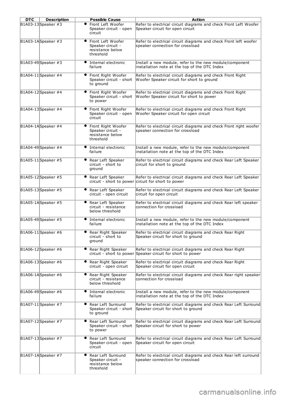
DT CDescriptionPossible CauseAction
B1A03-13Speaker #3Front Left W ooferSpeaker ci rcuit - opencircuit
Refer to el ect ri cal circui t diagrams and check Front Left W ooferSpeaker circui t for open circui t
B1A03-1ASpeaker #3Front Left W ooferSpeaker ci rcuit -res is t ance belowthreshold
Refer to el ect ri cal circui t diagrams and check Front left woofers peaker connect ion for cros s load
B1A03-49Speaker #3Int ernal electroni cfai lureIns tall a new module, refer to the new modul e/componenti nst all ati on not e at t he t op of the DTC Index
B1A04-11Speaker #4Front Right W ooferSpeaker ci rcuit - s hortto ground
Refer to el ect ri cal circui t diagrams and check Front RightW oofer Speaker ci rcuit for short to ground
B1A04-12Speaker #4Front Right W ooferSpeaker ci rcuit - s hortto power
Refer to el ect ri cal circui t diagrams and check Front RightW oofer Speaker ci rcuit for short to power
B1A04-13Speaker #4Front Right W ooferSpeaker ci rcuit - opencircuit
Refer to el ect ri cal circui t diagrams and check Front RightW oofer Speaker ci rcuit for open ci rcuit
B1A04-1ASpeaker #4Front Right W ooferSpeaker ci rcuit -res is t ance belowthreshold
Refer to el ect ri cal circui t diagrams and check Front ri ght woofers peaker connect ion for cros s load
B1A04-49Speaker #4Int ernal electroni cfai lureIns tall a new module, refer to the new modul e/componenti nst all ati on not e at t he t op of the DTC Index
B1A05-11Speaker #5Rear Left Speakercircuit - short toground
Refer to el ect ri cal circui t diagrams and check Rear Left Speakerci rcuit for s hort t o ground
B1A05-12Speaker #5Rear Left Speakercircuit - short to powerRefer to el ect ri cal circui t diagrams and check Rear Left Speakerci rcuit for s hort t o power
B1A05-13Speaker #5Rear Left Speakercircuit - open circui tRefer to el ect ri cal circui t diagrams and check Rear Left Speakerci rcuit for open circui t
B1A05-1ASpeaker #5Rear Left Speakercircuit - res is tancebelow t hres hold
Refer to el ect ri cal circui t diagrams and check Rear l eft s peakerconnect ion for cross l oad
B1A05-49Speaker #5Int ernal electroni cfai lureIns tall a new module, refer to the new modul e/componenti nst all ati on not e at t he t op of the DTC Index
B1A06-11Speaker #6Rear Ri ght Speakercircuit - short toground
Refer to el ect ri cal circui t diagrams and check Rear Ri ghtSpeaker circui t for s hort t o ground
B1A06-12Speaker #6Rear Ri ght Speakercircuit - short to powerRefer to el ect ri cal circui t diagrams and check Rear Ri ghtSpeaker circui t for s hort t o power
B1A06-13Speaker #6Rear Ri ght Speakercircuit - open circui tRefer to el ect ri cal circui t diagrams and check Rear Ri ghtSpeaker circui t for open circui t
B1A06-1ASpeaker #6Rear Ri ght Speakercircuit - res is tancebelow t hres hold
Refer to el ect ri cal circui t diagrams and check Rear right s peakerconnect ion for cross l oad
B1A06-49Speaker #6Int ernal electroni cfai lureIns tall a new module, refer to the new modul e/componenti nst all ati on not e at t he t op of the DTC Index
B1A07-11Speaker #7Rear Left SurroundSpeaker ci rcuit - s hortto ground
Refer to el ect ri cal circui t diagrams and check Rear Left SurroundSpeaker circui t for s hort t o ground
B1A07-12Speaker #7Rear Left SurroundSpeaker ci rcuit - s hortto power
Refer to el ect ri cal circui t diagrams and check Rear Left SurroundSpeaker circui t for s hort t o power
B1A07-13Speaker #7Rear Left SurroundSpeaker ci rcuit - opencircuit
Refer to el ect ri cal circui t diagrams and check Rear Left SurroundSpeaker circui t for open circui t
B1A07-1ASpeaker #7Rear Left SurroundSpeaker ci rcuit -res is t ance belowthreshold
Refer to el ect ri cal circui t diagrams and check Rear l eft s urrounds peaker connect ion for cros s load
Page 50 of 3229
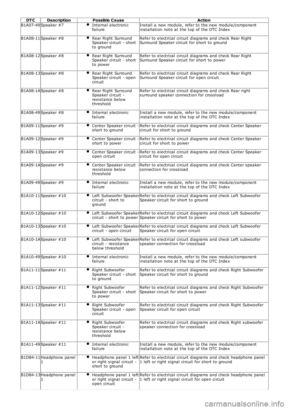
DT CDescriptionPossible CauseAction
B1A07-49Speaker #7Int ernal electroni cfai lureIns tall a new module, refer to the new modul e/componenti nst all ati on not e at t he t op of the DTC Index
B1A08-11Speaker #8Rear Ri ght SurroundSpeaker ci rcuit - s hortto ground
Refer to el ect ri cal circui t diagrams and check Rear Ri ghtSurround Speaker circuit for s hort to ground
B1A08-12Speaker #8Rear Ri ght SurroundSpeaker ci rcuit - s hortto power
Refer to el ect ri cal circui t diagrams and check Rear Ri ghtSurround Speaker circuit for s hort to power
B1A08-13Speaker #8Rear Ri ght SurroundSpeaker ci rcuit - opencircuit
Refer to el ect ri cal circui t diagrams and check Rear Ri ghtSurround Speaker circuit for open ci rcuit
B1A08-1ASpeaker #8Rear Ri ght SurroundSpeaker ci rcuit -res is t ance belowthreshold
Refer to el ect ri cal circui t diagrams and check Rear rights urround s peaker connect ion for cros sl oad
B1A08-49Speaker #8Int ernal electroni cfai lureIns tall a new module, refer to the new modul e/componenti nst all ati on not e at t he t op of the DTC Index
B1A09-11Speaker #9Cent er Speaker ci rcuit -s hort to groundRefer to el ect ri cal circui t diagrams and check Cent er Speakerci rcuit for s hort t o ground
B1A09-12Speaker #9Cent er Speaker ci rcuit -s hort to powerRefer to el ect ri cal circui t diagrams and check Cent er Speakerci rcuit for s hort t o power
B1A09-13Speaker #9Cent er Speaker ci rcuit -open ci rcuitRefer to el ect ri cal circui t diagrams and check Cent er Speakerci rcuit for open circui t
B1A09-1ASpeaker #9Cent er Speaker ci rcuit -res is t ance belowthreshold
Refer to el ect ri cal circui t diagrams and check Cent er speakerconnect ion for cross l oad
B1A09-49Speaker #9Int ernal electroni cfai lureIns tall a new module, refer to the new modul e/componenti nst all ati on not e at t he t op of the DTC Index
B1A10-11Speaker #10Left Subwoofer Speakercircuit - short toground
Refer to el ect ri cal circui t diagrams and check Left SubwooferSpeaker circui t for s hort t o ground
B1A10-12Speaker #10Left Subwoofer Speakercircuit - short to powerRefer to el ect ri cal circui t diagrams and check Left SubwooferSpeaker circui t for s hort t o power
B1A10-13Speaker #10Left Subwoofer Speakercircuit - open circui tRefer to el ect ri cal circui t diagrams and check Left SubwooferSpeaker circui t for open circui t
B1A10-1ASpeaker #10Left Subwoofer Speakercircuit - res is tancebelow t hres hold
Refer to el ect ri cal circui t diagrams and check Left s ubwoofers peaker connect ion for cros s load
B1A10-49Speaker #10Int ernal electroni cfai lureIns tall a new module, refer to the new modul e/componenti nst all ati on not e at t he t op of the DTC Index
B1A11-11Speaker #11Right SubwooferSpeaker ci rcuit - s hortto ground
Refer to el ect ri cal circui t diagrams and check Right SubwooferSpeaker circui t for s hort t o ground
B1A11-12Speaker #11Right SubwooferSpeaker ci rcuit - s hortto power
Refer to el ect ri cal circui t diagrams and check Right SubwooferSpeaker circui t for s hort t o power
B1A11-13Speaker #11Right SubwooferSpeaker ci rcuit - opencircuit
Refer to el ect ri cal circui t diagrams and check Right SubwooferSpeaker circui t for open circui t
B1A11-1ASpeaker #11Right SubwooferSpeaker ci rcuit -res is t ance belowthreshold
Refer to el ect ri cal circui t diagrams and check Right s ubwoofers peaker connect ion for cros s load
B1A11-49Speaker #11Int ernal electroni cfai lureIns tall a new module, refer to the new modul e/componenti nst all ati on not e at t he t op of the DTC Index
B1D84-11Headphone panel1Headphone panel 1 leftor ri ght s i gnal circuit -s hort to ground
Refer to el ect ri cal circui t diagrams and check headphone panel1 left or right s ignal ci rcuit for short to ground
B1D84-13Headphone panel1Headphone panel 1 leftor ri ght s i gnal circuit -open ci rcuit
Refer to el ect ri cal circui t diagrams and check headphone panel1 left or right s ignal ci rcuit for open ci rcuit
Page 51 of 3229
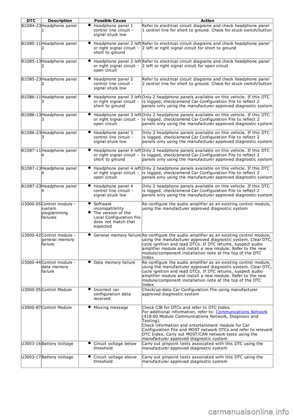
DT CDescriptionPossible CauseAction
B1D84-23Headphone panel1Headphone panel 1cont rol li ne circui t -s ignal s t uck low
Refer to el ect ri cal circui t diagrams and check headphone panel1 cont rol li ne for s hort t o ground. Check for st uck s wit ch/but t on
B1D85-11Headphone panel2Headphone panel 2 leftor ri ght s i gnal circuit -s hort to ground
Refer to el ect ri cal circui t diagrams and check headphone panel2 left or right s ignal ci rcuit for short to ground
B1D85-13Headphone panel2Headphone panel 2 leftor ri ght s i gnal circuit -open ci rcuit
Refer to el ect ri cal circui t diagrams and check headphone panel2 left or right s ignal ci rcuit for open ci rcuit
B1D85-23Headphone panel2Headphone panel 2cont rol li ne circui t -s ignal s t uck low
Refer to el ect ri cal circui t diagrams and check headphone panel2 cont rol li ne for s hort t o ground. Check for st uck s wit ch/but t on
B1D86-11Headphone panel3Headphone panel 3 leftor ri ght s i gnal circuit -s hort to ground
O nl y 2 headphone panels avail abl e on t his vehicle. If this DTCi s l ogged, check/amend Car Configurat ion Fi le t o refl ect 2panels onl y usi ng t he manufact urer approved diagnost ic s ys tem
B1D86-13Headphone panel3Headphone panel 3 leftor ri ght s i gnal circuit -open ci rcuit
O nl y 2 headphone panels avail abl e on t his vehicle. If this DTCi s l ogged, check/amend Car Configurat ion Fi le t o refl ect 2panels onl y usi ng t he manufact urer approved diagnost ic s ys tem
B1D86-23Headphone panel3Headphone panel 3cont rol li ne circui t -s ignal s t uck low
O nl y 2 headphone panels avail abl e on t his vehicle. If this DTCi s l ogged, check/amend Car Configurat ion Fi le t o refl ect 2panels onl y usi ng t he manufact urer approved diagnost ic s ys tem
B1D87-11Headphone panel4Headphone panel 4 leftor ri ght s i gnal circuit -s hort to ground
O nl y 2 headphone panels avail abl e on t his vehicle. If this DTCi s l ogged, check/amend Car Configurat ion Fi le t o refl ect 2panels onl y usi ng t he manufact urer approved diagnost ic s ys tem
B1D87-13Headphone panel4Headphone panel 4 leftor ri ght s i gnal circuit -open ci rcuit
O nl y 2 headphone panels avail abl e on t his vehicle. If this DTCi s l ogged, check/amend Car Configurat ion Fi le t o refl ect 2panels onl y usi ng t he manufact urer approved diagnost ic s ys tem
B1D87-23Headphone panel4Headphone panel 4cont rol li ne circui t -s ignal s t uck low
O nl y 2 headphone panels avail abl e on t his vehicle. If this DTCi s l ogged, check/amend Car Configurat ion Fi le t o refl ect 2panels onl y usi ng t he manufact urer approved diagnost ic s ys tem
U3000-05Control modul e -s ys t emprogrammingfai lures
Soft wareincompati bi li tyThe vers ion of t heLocal Configurat ion fil edoes not mat ch t hatexpected
Re-configure the audio ampl ifier as an exis t ing control modul e,us ing the manufact urer approved di agnos t ic s yst em
U3000-42Control modul e -general memoryfai lure
General memory fail ureRe-configure the audio ampl ifier as an exis t ing control modul e,us ing the manufact urer approved di agnos t ic s yst em. Clear DTC,cycle i gni ti on and read DTCs . If DTC ret urns , sus pect audioampl ifier module and i nst all a new module. Refer to the newmodul e/component ins t al lat ion not e at the top of t he DTCIndex
U3000-44Control modul e -data memoryfai lure
Data memory fail ureRe-configure the audio ampl ifier as an exis t ing control modul e,us ing the manufact urer approved di agnos t ic s yst em. Clear DTC,cycle i gni ti on and read DTCs . If DTC ret urns , sus pect audioampl ifier module and i nst all a new module. Refer to the newmodul e/component ins t al lat ion not e at the top of t he DTCIndex
U3000-55Control ModuleIncorrect carconfigurat ion dat areceived
Check/up-dat e Car Configurat ion Fil e us ing manufact urerapproved diagnos ti c sys t em
U3000-87Control ModuleMis s ing mess ageCheck CJB for DTCs and refer to DTC Index.For addit ional i nformati on, refer to: Communi cat ions Net work(418-00 Module Communicat ions Net work, Diagnosi s andTes ti ng).Check informat ion and ent ertai nment modul e for CarConfigurat ion Fil e and MOST net work DTCs and refer t o rel evantDTC Index. Carry out MOST/CAN network t es t s us ing t hemanufact urer approved diagnos t ic s yst em
U3003-16Batt ery Vol tageCircui t vol tage belowthresholdCarry out pinpoint t est s as s oci at ed wi th this DTC usi ng t hemanufact urer approved diagnos t ic s yst em
U3003-17Batt ery Vol tageCircui t vol tage abovethresholdCarry out pinpoint t est s as s oci at ed wi th this DTC usi ng t hemanufact urer approved diagnos t ic s yst em
Page 55 of 3229

DT CDescriptionPossible CauseAction
sys tem, carry out t he lat eral acceleromet ercal ibrat ion rout ineFor addit ional informati on, refer t o:Acceleromet er (206-09C Ant i-Lock Cont rol -St abil it y Ass i st , Removal and Inst all ati on).
C0061-28Lateral Accel erati on Sensor- Signal bias level out ofrange/zero adjus tmentfai lure
Sens or incorrect lycal ibrat edClear DTC and ret est i f DTC ret urnsUsi ng t he manufact urer approved diagnost icsys tem, carry out t he lat eral acceleromet ercal ibrat ion rout ineFor addit ional informati on, refer t o:Acceleromet er (206-09C Ant i-Lock Cont rol -St abil it y Ass i st , Removal and Inst all ati on).
C0061-64Lateral Accel erati on Sensor- Signal plausi bili ty fail ureLat eral accelerati onsens or int ernalfail ure
Carry out pi npoi nt t es ts as s oci ated wi th thi sDTC usi ng t he manufacturer approved diagnost icsys tem. Cl ear DTC and ret est i f DTC ret urns .Ins tal l a new s ensorUsi ng t he manufact urer approved diagnost icsys tem, carry out t he lat eral acceleromet ercal ibrat ion rout ineFor addit ional informati on, refer t o:Acceleromet er (206-09C Ant i-Lock Cont rol -St abil it y Ass i st , Removal and Inst all ati on).
C0062-01Longi tudinal Accelerati onSens or - General electricalfai lure
Sens or ci rcuit - s hortto ground, s hort t opower, open ci rcuitInt ernal sens orfail ure
Carry out pi npoi nt t es ts as s oci ated wi th thi sDTC usi ng t he manufacturer approved diagnost icsys tem. Cl ear DTC and ret est i f DTC ret urns .Ins tal l a new s ensorUsi ng t he manufact urer approved diagnost icsys tem, carry out t he longit udi nal accel eromet ercal ibrat ion rout ineFor addit ional informati on, refer t o:Acceleromet er (206-09C Ant i-Lock Cont rol -St abil it y Ass i st , Removal and Inst all ati on).
C0062-28Longi tudinal Accelerati onSens or - Signal bias l evelout of range/zeroadjus tment failure
Sens or incorrect lycal ibrat edClear DTC and ret est i f DTC ret urnsUsi ng t he manufact urer approved diagnost icsys tem, carry out t he longit udi nal accel eromet ercal ibrat ion rout ineFor addit ional informati on, refer t o:Acceleromet er (206-09C Ant i-Lock Cont rol -St abil it y Ass i st , Removal and Inst all ati on).
C0062-64Longi tudinal Accelerati onSens or - Signal plausi bil it yfai lure
Longit udinalAccelerat ion sens orint ernal fail ure
Carry out pi npoi nt t es ts as s oci ated wi th thi sDTC usi ng t he manufacturer approved diagnost icsys tem. Cl ear DTC and ret est i f DTC ret urns .Ins tal l a new s ensorUsi ng t he manufact urer approved diagnost icsys tem, carry out t he longit udi nal accel eromet ercal ibrat ion rout ineFor addit ional informati on, refer t o:Acceleromet er (206-09C Ant i-Lock Cont rol -St abil it y Ass i st , Removal and Inst all ati on).
C0063-01Y aw Rat e Sens or - Generalelectrical fail ureY aw rat e s ensorci rcuit - s hort t oground, power, openci rcuitY aw rat e s ensorint ernal fail ure
Refer to el ect ri cal circui t diagrams and checkY aw rat e s ensor circui t for s hort t o ground,power, open ci rcuit . Clear DTC and ret est i f DTCret urns. Ins tall a new s ens orUsi ng t he manufact urer approved diagnost icsys tem, carry out t he yaw rat e s ensorcal ibrat ion rout ineFor addit ional informati on, refer t o:Acceleromet er (206-09C Ant i-Lock Cont rol -St abil it y Ass i st , Removal and Inst all ati on).
C0063-28Y aw Rat e Sens or - Signalbias l evel out of range/zeroadjus tment failure
Sens or incorrect lycal ibrat edClear DTC and ret est i f DTC ret urns .Usi ng t he manufact urer approved diagnost icsys tem, carry out t he yaw rat e s ensorcal ibrat ion rout ineFor addit ional informati on, refer t o:Acceleromet er (206-09C Ant i-Lock Cont rol -St abil it y Ass i st , Removal and Inst all ati on).
C0063-64Y aw Rat e Sens or - Signalplaus ibil it y fai lureY aw rat e s ensorint ernal fail ureCarry out pi npoi nt t es ts as s oci ated wi th thi sDTC usi ng t he manufacturer approved diagnost icsys tem. Cl ear DTC and ret est i f DTC ret urns .Ins tal l a new s ensorUsi ng t he manufact urer approved diagnost icsys tem, carry out t he yaw rat e s ensorcal ibrat ion rout ineFor addit ional informati on, refer t o:Acceleromet er (206-09C Ant i-Lock Cont rol -St abil it y Ass i st , Removal and Inst all ati on).
Page 56 of 3229
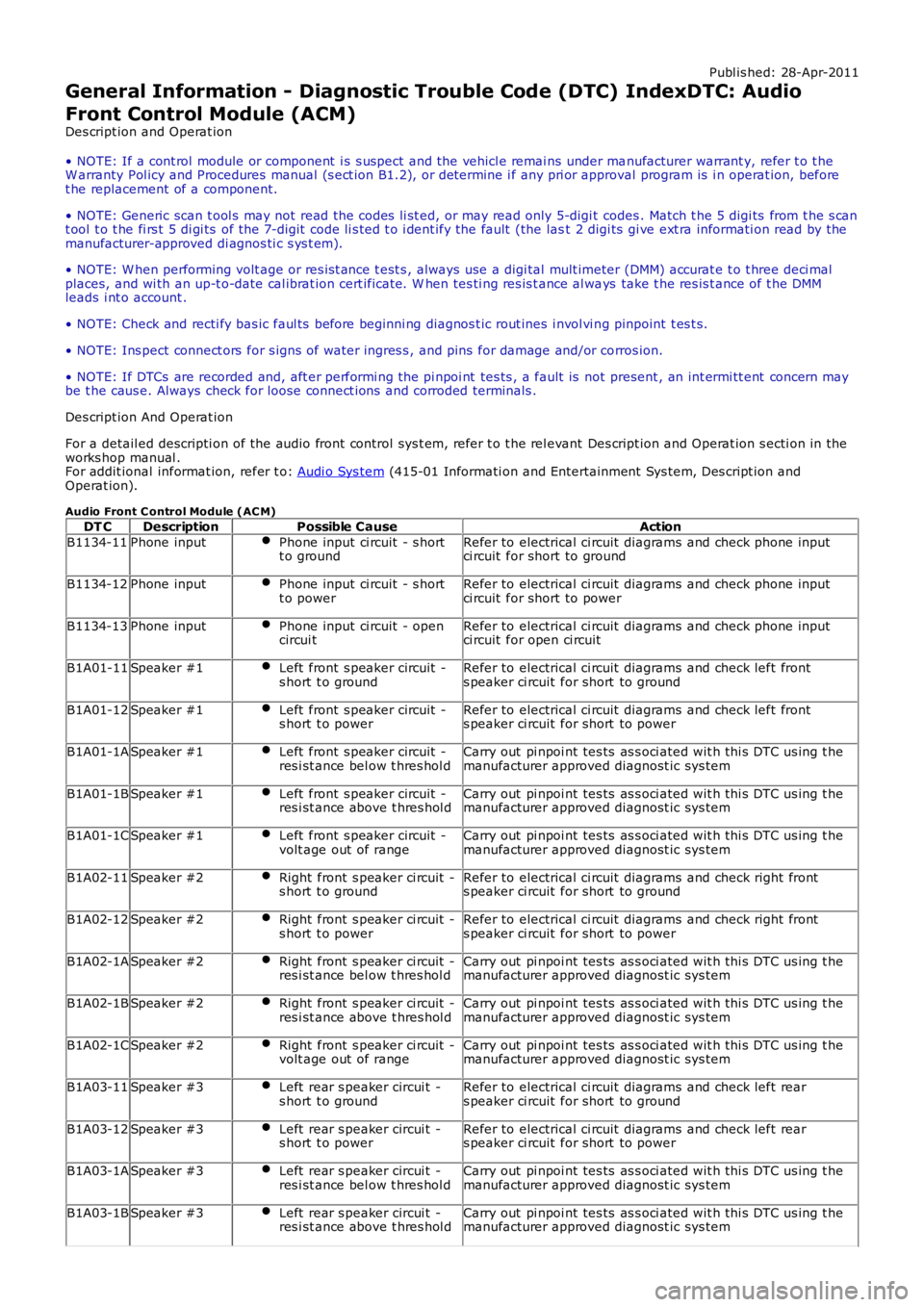
Publ is hed: 28-Apr-2011
General Information - Diagnostic Trouble Code (DTC) IndexDTC: Audio
Front Control Module (ACM)
Des cript ion and Operat ion
• NOTE: If a cont rol module or component i s s uspect and the vehicl e remai ns under manufacturer warrant y, refer t o t heW arranty Pol icy and Procedures manual (s ect ion B1.2), or determine i f any pri or approval program is i n operat ion, beforet he replacement of a component.
• NOTE: Generic scan t ool s may not read the codes li st ed, or may read only 5-digi t codes . Match t he 5 digi ts from t he s cant ool t o t he fi rs t 5 di gi ts of the 7-digit code li s ted t o i dent ify the fault (the last 2 digi ts gi ve ext ra informati on read by themanufacturer-approved di agnos ti c s ys t em).
• NOTE: W hen performing volt age or res is t ance t est s , always use a digi tal mult imeter (DMM) accurat e t o t hree deci malplaces, and wi th an up-t o-date cal ibrat ion cert ificate. W hen tes ti ng res is t ance al ways take t he res is t ance of t he DMMleads i nt o account .
• NOTE: Check and recti fy bas ic faul ts before beginni ng diagnos t ic rout ines i nvol vi ng pinpoint t es t s.
• NOTE: Ins pect connect ors for s igns of water ingres s , and pins for damage and/or corros ion.
• NOTE: If DTCs are recorded and, aft er performi ng the pi npoi nt tes ts , a fault is not present , an int ermi tt ent concern maybe t he caus e. Always check for loose connect ions and corroded terminals .
Des cript ion And Operat ion
For a detail ed descripti on of the audio front control sys t em, refer t o t he rel evant Des cript ion and Operat ion s ecti on in theworks hop manual .For addit ional informat ion, refer t o: Audi o Sys tem (415-01 Informati on and Entertainment Sys tem, Des cript ion andOperat ion).
Audio Front C ontrol Module (AC M)
DT CDescriptionPossible CauseAction
B1134-11Phone inputPhone input ci rcuit - s hortt o groundRefer to electrical ci rcuit diagrams and check phone inputci rcuit for short to ground
B1134-12Phone inputPhone input ci rcuit - s hortt o powerRefer to electrical ci rcuit diagrams and check phone inputci rcuit for short to power
B1134-13Phone inputPhone input ci rcuit - opencircui tRefer to electrical ci rcuit diagrams and check phone inputci rcuit for open ci rcuit
B1A01-11Speaker #1Left front s peaker circuit -s hort t o groundRefer to electrical ci rcuit diagrams and check left fronts peaker ci rcuit for short to ground
B1A01-12Speaker #1Left front s peaker circuit -s hort t o powerRefer to electrical ci rcuit diagrams and check left fronts peaker ci rcuit for short to power
B1A01-1ASpeaker #1Left front s peaker circuit -res i st ance bel ow t hres hol dCarry out pi npoi nt tes ts as s oci ated wit h thi s DTC us ing t hemanufacturer approved diagnost ic sys tem
B1A01-1BSpeaker #1Left front s peaker circuit -res i st ance above t hres hol dCarry out pi npoi nt tes ts as s oci ated wit h thi s DTC us ing t hemanufacturer approved diagnost ic sys tem
B1A01-1CSpeaker #1Left front s peaker circuit -volt age out of rangeCarry out pi npoi nt tes ts as s oci ated wit h thi s DTC us ing t hemanufacturer approved diagnost ic sys tem
B1A02-11Speaker #2Right front s peaker ci rcuit -s hort t o groundRefer to electrical ci rcuit diagrams and check right fronts peaker ci rcuit for short to ground
B1A02-12Speaker #2Right front s peaker ci rcuit -s hort t o powerRefer to electrical ci rcuit diagrams and check right fronts peaker ci rcuit for short to power
B1A02-1ASpeaker #2Right front s peaker ci rcuit -res i st ance bel ow t hres hol dCarry out pi npoi nt tes ts as s oci ated wit h thi s DTC us ing t hemanufacturer approved diagnost ic sys tem
B1A02-1BSpeaker #2Right front s peaker ci rcuit -res i st ance above t hres hol dCarry out pi npoi nt tes ts as s oci ated wit h thi s DTC us ing t hemanufacturer approved diagnost ic sys tem
B1A02-1CSpeaker #2Right front s peaker ci rcuit -volt age out of rangeCarry out pi npoi nt tes ts as s oci ated wit h thi s DTC us ing t hemanufacturer approved diagnost ic sys tem
B1A03-11Speaker #3Left rear s peaker circui t -s hort t o groundRefer to electrical ci rcuit diagrams and check left rears peaker ci rcuit for short to ground
B1A03-12Speaker #3Left rear s peaker circui t -s hort t o powerRefer to electrical ci rcuit diagrams and check left rears peaker ci rcuit for short to power
B1A03-1ASpeaker #3Left rear s peaker circui t -res i st ance bel ow t hres hol dCarry out pi npoi nt tes ts as s oci ated wit h thi s DTC us ing t hemanufacturer approved diagnost ic sys tem
B1A03-1BSpeaker #3Left rear s peaker circui t -res i st ance above t hres hol dCarry out pi npoi nt tes ts as s oci ated wit h thi s DTC us ing t hemanufacturer approved diagnost ic sys tem
Page 57 of 3229
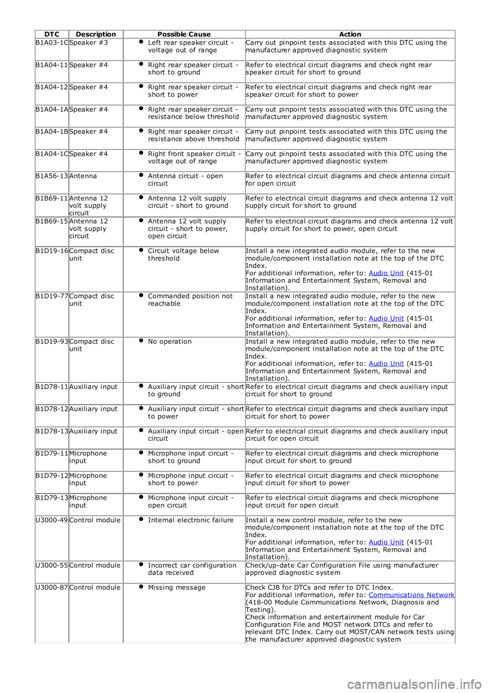
DT CDescriptionPossible CauseAction
B1A03-1CSpeaker #3Left rear s peaker circui t -volt age out of rangeCarry out pi npoi nt tes ts as s oci ated wit h thi s DTC us ing t hemanufacturer approved diagnost ic sys tem
B1A04-11Speaker #4Right rear s peaker circui t -s hort t o groundRefer to electrical ci rcuit diagrams and check right rears peaker ci rcuit for short to ground
B1A04-12Speaker #4Right rear s peaker circui t -s hort t o powerRefer to electrical ci rcuit diagrams and check right rears peaker ci rcuit for short to power
B1A04-1ASpeaker #4Right rear s peaker circui t -res i st ance bel ow t hres hol dCarry out pi npoi nt tes ts as s oci ated wit h thi s DTC us ing t hemanufacturer approved diagnost ic sys tem
B1A04-1BSpeaker #4Right rear s peaker circui t -res i st ance above t hres hol dCarry out pi npoi nt tes ts as s oci ated wit h thi s DTC us ing t hemanufacturer approved diagnost ic sys tem
B1A04-1CSpeaker #4Right front s peaker ci rcuit -volt age out of rangeCarry out pi npoi nt tes ts as s oci ated wit h thi s DTC us ing t hemanufacturer approved diagnost ic sys tem
B1A56-13AntennaAntenna circui t - opencircui tRefer to electrical ci rcuit diagrams and check antenna circui tfor open circuit
B1B69-11Antenna 12volt s uppl ycircuit
Antenna 12 volt supplycircui t - s hort to groundRefer to electrical ci rcuit diagrams and check antenna 12 volts upply ci rcuit for short to ground
B1B69-15Antenna 12volt s uppl ycircuit
Antenna 12 volt supplycircui t - s hort to power,open circuit
Refer to electrical ci rcuit diagrams and check antenna 12 volts upply ci rcuit for short to power, open ci rcuit
B1D19-16Compact di scunitCircui t volt age bel owt hres hol dIns t al l a new i ntegrat ed audi o module, refer to the newmodule/component i nst all at ion not e at t he top of t he DTCIndex.For addit ional informati on, refer t o: Audi o Unit (415-01Informat ion and Ent ertai nment Sys tem, Removal andIns t al lat ion).B1D19-77Compact di scunitCommanded posi ti on notreachabl eIns t al l a new i ntegrat ed audi o module, refer to the newmodule/component i nst all at ion not e at t he top of t he DTCIndex.For addit ional informati on, refer t o: Audi o Unit (415-01Informat ion and Ent ertai nment Sys tem, Removal andIns t al lat ion).
B1D19-93Compact di scunitNo operat ionIns t al l a new i ntegrat ed audi o module, refer to the newmodule/component i nst all at ion not e at t he top of t he DTCIndex.For addit ional informati on, refer t o: Audi o Unit (415-01Informat ion and Ent ertai nment Sys tem, Removal andIns t al lat ion).
B1D78-11Auxi li ary i nputAuxili ary i nput ci rcuit - s hortt o groundRefer to electrical ci rcuit diagrams and check auxi li ary i nputci rcuit for short to ground
B1D78-12Auxi li ary i nputAuxili ary i nput ci rcuit - s hortt o powerRefer to electrical ci rcuit diagrams and check auxi li ary i nputci rcuit for short to power
B1D78-13Auxi li ary i nputAuxili ary i nput ci rcuit - opencircui tRefer to electrical ci rcuit diagrams and check auxi li ary i nputci rcuit for open ci rcuit
B1D79-11MicrophoneinputMi crophone i nput circui t -s hort t o groundRefer to electrical ci rcuit diagrams and check mi crophoneinput ci rcuit for short to ground
B1D79-12MicrophoneinputMi crophone i nput circui t -s hort t o powerRefer to electrical ci rcuit diagrams and check mi crophoneinput ci rcuit for short to power
B1D79-13MicrophoneinputMi crophone i nput circui t -open circuitRefer to electrical ci rcuit diagrams and check mi crophoneinput ci rcuit for open ci rcuit
U3000-49Control modul eInternal electronic fai lureIns t al l a new control modul e, refer t o t he newmodule/component i nst all at ion not e at t he top of t he DTCIndex.For addit ional informati on, refer t o: Audi o Unit (415-01Informat ion and Ent ertai nment Sys tem, Removal andIns t al lat ion).
U3000-55Control modul eIncorrect car configurat iondata receivedCheck/up-dat e Car Configurat ion Fi le us i ng manufact urerapproved di agnos ti c s yst em
U3000-87Control modul eMi ss i ng mes sageCheck CJB for DTCs and refer t o DTC Index.For addit ional informati on, refer t o: Communicati ons Net work(418-00 Modul e Communicati ons Network, Di agnos is andTes t ing).Check i nformat ion and ent ert ainment module for CarConfigurat ion Fi le and MO ST net work DTCs and refer t orel evant DTC Index. Carry out MOST/CAN net work t es ts us ingthe manufact urer approved diagnos t ic s ys tem
Page 60 of 3229
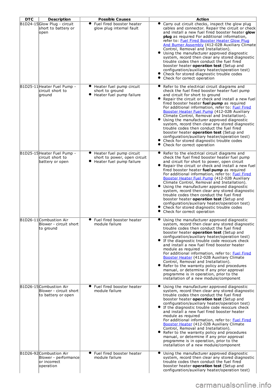
DT CDescriptionPossible CausesAction
B1D24-15Glow Plug - circui ts hort t o batt ery oropen
Fuel fired boos t er heaterglow pl ug int ernal faultCarry out ci rcuit checks , ins pect t he glow pl ugcables and connect or. Repair t he ci rcuit or checkand ins tal l a new fuel fired boos t er heater glowplug as requi red For addit ional i nformati on,refer t o: Fuel Fired Boost er Heat er Glow PlugAnd Burner Ass embly (412-02B Auxil iary Cli mateCont rol , Removal and Ins t allat ion).Usi ng t he manufacturer approved diagnost icsys t em, record t hen clear any st ored di agnos ti ctroubl e codes t hen conduct the fuel fi redboos t er heater operation test (Set up andconfigurat ion/auxili ary heat er/operat ion t es t)Check for st ored di agnos ti c troubl e codesCheck for correct operat ion
B1D25-11Heater Fuel Pump -circuit short toground
Heat er fuel pump circui ts hort to groundHeat er fuel pump failure
Refer to the el ect ri cal circui t diagrams andcheck t he fuel fi red boos ter heater fuel pumpand ci rcuit for short to groundRepai r the circui t or check and ins t al l a new fuelfi red boos ter heat er fuel pump as requiredFor addit ional informati on, refer t o: Fuel FiredBoos t er Heat er Fuel Pump (412-02B Auxi li aryClimate Cont rol, Removal and Ins tal lat ion).Usi ng t he manufacturer approved diagnost icsys t em, record t hen clear any st ored di agnos ti ctroubl e codes t hen conduct the fuel fi redboos t er heater operation test (Set up andconfigurat ion/auxili ary heat er/operat ion t es t)Check for st ored di agnos ti c troubl e codesCheck for correct operat ion
B1D25-15Heater Fuel Pump -circuit short tobatt ery or open
Heat er fuel pump circui ts hort to power, open ci rcuitHeat er fuel pump failure
Refer to the el ect ri cal circui t diagrams andcheck t he fuel fi red boos ter heater fuel pumpand ci rcuit for short to power, open ci rcuitRepai r the circui t or check and ins t al l a new fuelfi red boos ter heat er fuel pump as requiredFor addit ional informati on, refer t o: Fuel FiredBoos t er Heat er Fuel Pump (412-02B Auxi li aryClimate Cont rol, Removal and Ins tal lat ion).Usi ng t he manufacturer approved diagnost icsys t em, record t hen clear any st ored di agnos ti ctroubl e codes t hen conduct the fuel fi redboos t er heater operation test (Set up andconfigurat ion/auxili ary heat er/operat ion t es t)Check for st ored di agnos ti c troubl e codesCheck for correct operat ion
B1D26-11Combust ion Ai rBlower - circui t shortt o ground
Fuel fired boos t er heatermodule failureUsi ng t he manufacturer approved diagnost icsys t em, record t hen clear any st ored di agnos ti ctroubl e codes t hen conduct the fuel fi redboos t er heater operation test (Set up andconfigurat ion/auxili ary heat er/operat ion t es t)If t he diagnost ic troubl e code reoccurs checkand ins tal l a new fuel fired boos t er heatermodul e as requi redFor addit ional informati on, refer t o: Fuel FiredBoos t er Heat er (412-02B Auxil iary Climat eCont rol , Removal and Ins t allat ion).Refer to the warrant y policy and proceduresmanual , or det ermi ne if any prior approvalprogramme is in operat ion, pri or t o t heins tal lati on of a new modul e/component
B1D26-15Combust ion Ai rBlower - circui t shortt o batt ery or open
Fuel fired boos t er heatermodule failureUsi ng t he manufacturer approved diagnost icsys t em, record t hen clear any st ored di agnos ti ctroubl e codes t hen conduct the fuel fi redboos t er heater operation test (Set up andconfigurat ion/auxili ary heat er/operat ion t es t)If t he diagnost ic troubl e code reoccurs checkand ins tal l a new fuel fired boos t er heatermodul e as requi redFor addit ional informati on, refer t o: Fuel FiredBoos t er Heat er (412-02B Auxil iary Climat eCont rol , Removal and Ins t allat ion).Refer to the warrant y policy and proceduresmanual , or det ermi ne if any prior approvalprogramme is in operat ion, pri or t o t heins tal lati on of a new modul e/component
B1D26-92Combust ion Ai rBlower - performanceor incorrectoperati on
Fuel fired boos t er heatermodule failureUsi ng t he manufacturer approved diagnost icsys t em, record t hen clear any st ored di agnos ti ctroubl e codes t hen conduct the fuel fi redboos t er heater operation test (Set up andconfigurat ion/auxili ary heat er/operat ion t es t)
Page 61 of 3229
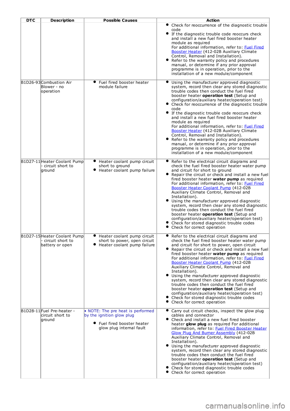
DT CDescriptionPossible CausesAction
Check for reoccurrence of t he diagnost ic troubl ecodeIf t he diagnost ic troubl e code reoccurs checkand ins tal l a new fuel fired boos t er heatermodul e as requi redFor addit ional informati on, refer t o: Fuel FiredBoos t er Heat er (412-02B Auxil iary Climat eCont rol , Removal and Ins t allat ion).Refer to the warrant y policy and proceduresmanual , or det ermi ne if any prior approvalprogramme is in operat ion, pri or t o t heins tal lati on of a new modul e/component
B1D26-93Combust ion Ai rBlower - nooperati on
Fuel fired boos t er heatermodule failureUsi ng t he manufacturer approved diagnost icsys t em, record t hen clear any st ored di agnos ti ctroubl e codes t hen conduct the fuel fi redboos t er heater operation test (Set up andconfigurat ion/auxili ary heat er/operat ion t es t)Check for reoccurrence of t he diagnost ic troubl ecodeIf t he diagnost ic troubl e code reoccurs checkand ins tal l a new fuel fired boos t er heatermodul e as requi redFor addit ional informati on, refer t o: Fuel FiredBoos t er Heat er (412-02B Auxil iary Climat eCont rol , Removal and Ins t allat ion).Refer to the warrant y policy and proceduresmanual , or det ermi ne if any prior approvalprogramme is in operat ion, pri or t o t heins tal lati on of a new modul e/component
B1D27-11Heater Coolant Pump- circui t short toground
Heat er cool ant pump ci rcuits hort to groundHeat er cool ant pump fail ure
Refer to the el ect ri cal circui t diagrams andcheck t he fuel fi red boos ter heater water pumpand ci rcuit for short to groundRepai r the circui t or check and ins t al l a new fuelfi red boos ter heat er water pump as requi redFor addit ional informati on, refer t o: Fuel FiredBoos t er Heat er Cool ant Pump (412-02BAuxi liary Cli mate Cont rol , Removal andIns tal lat ion).Usi ng t he manufacturer approved diagnost icsys t em, record t hen clear any st ored di agnos ti ctroubl e codes t hen conduct the fuel fi redboos t er heater operation test (Set up andconfigurat ion/auxili ary heat er/operat ion t es t)Check for st ored di agnos ti c troubl e codesCheck for correct operat ion
B1D27-15Heater Coolant Pump- circui t short tobatt ery or open
Heat er cool ant pump ci rcuits hort to power, open ci rcuitHeat er cool ant pump fail ure
Refer to the el ect ri cal circui t diagrams andcheck t he fuel fi red boos ter heater water pumpand ci rcuit for short to power, open ci rcuitRepai r the circui t or check and ins t al l a new fuelfi red boos ter heat er water pump as requi redFor addit ional informati on, refer t o: Fuel FiredBoos t er Heat er Cool ant Pump (412-02BAuxi liary Cli mate Cont rol , Removal andIns tal lat ion).Usi ng t he manufacturer approved diagnost icsys t em, record t hen clear any st ored di agnos ti ctroubl e codes t hen conduct the fuel fi redboos t er heater operation test (Set up andconfigurat ion/auxili ary heat er/operat ion t es t)Check for st ored di agnos ti c troubl e codesCheck for correct operat ion
B1D28-11Fuel Pre-heater -circuit short toground
• NOTE: The pre heat i s performedby the ignit ion gl ow plug
Fuel fired boos t er heaterglow pl ug int ernal fault
Carry out ci rcuit checks , ins pect t he glow pl ugcables and connect orCheck and i ns t all a new fuel fi red boost erheat er glow plug as requi red For addi ti onalinformati on, refer t o: Fuel Fired Boos t er Heat erGlow Pl ug And Burner As sembl y (412-02BAuxi liary Cli mate Cont rol , Removal andIns tal lat ion).Usi ng t he manufacturer approved diagnost icsys t em, record t hen clear any st ored di agnos ti ctroubl e codes t hen conduct the fuel fi redboos t er heater operation test (Set up andconfigurat ion/auxili ary heat er/operat ion t es t)Check for st ored di agnos ti c troubl e codesCheck for correct operat ion
Page 64 of 3229
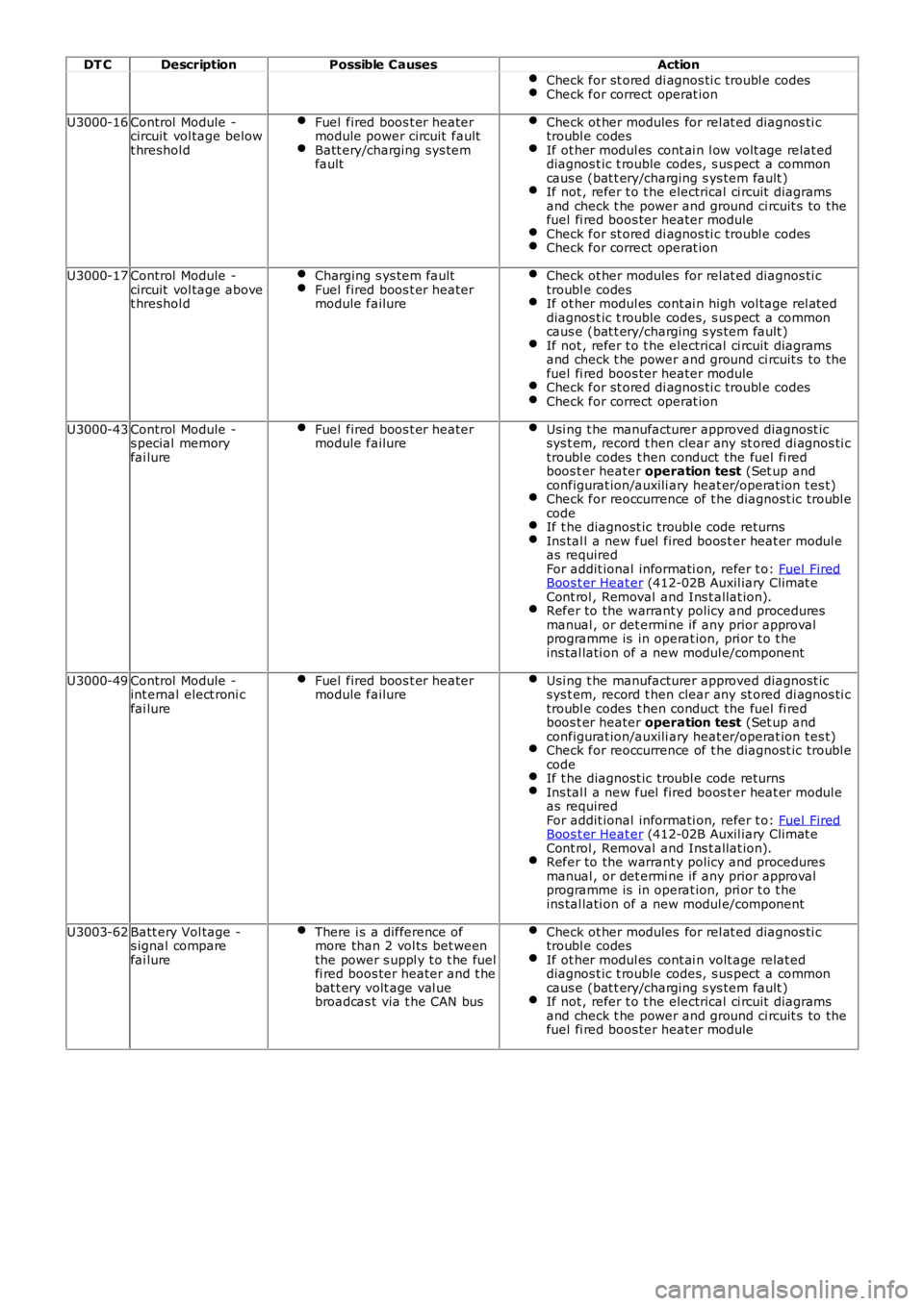
DT CDescriptionPossible CausesAction
Check for st ored di agnos ti c troubl e codesCheck for correct operat ion
U3000-16Control Module -circuit vol tage belowt hreshol d
Fuel fired boos t er heatermodule power circuit faultBatt ery/charging sys temfault
Check ot her modules for rel at ed diagnos ti ctroubl e codesIf ot her modul es cont ai n l ow volt age relat eddiagnos t ic t rouble codes, s us pect a commoncaus e (bat t ery/charging s ys tem fault )If not , refer t o t he electrical ci rcuit diagramsand check t he power and ground ci rcuit s to thefuel fi red boos ter heater moduleCheck for st ored di agnos ti c troubl e codesCheck for correct operat ion
U3000-17Control Module -circuit vol tage abovet hreshol d
Charging s ys tem faultFuel fired boos t er heatermodule failure
Check ot her modules for rel at ed diagnos ti ctroubl e codesIf ot her modul es cont ai n high vol tage rel ateddiagnos t ic t rouble codes, s us pect a commoncaus e (bat t ery/charging s ys tem fault )If not , refer t o t he electrical ci rcuit diagramsand check t he power and ground ci rcuit s to thefuel fi red boos ter heater moduleCheck for st ored di agnos ti c troubl e codesCheck for correct operat ion
U3000-43Control Module -s pecial memoryfai lure
Fuel fired boos t er heatermodule failureUsi ng t he manufacturer approved diagnost icsys t em, record t hen clear any st ored di agnos ti ctroubl e codes t hen conduct the fuel fi redboos t er heater operation test (Set up andconfigurat ion/auxili ary heat er/operat ion t es t)Check for reoccurrence of t he diagnost ic troubl ecodeIf t he diagnost ic troubl e code returnsIns tal l a new fuel fired boos t er heat er modul eas requiredFor addit ional informati on, refer t o: Fuel FiredBoos t er Heat er (412-02B Auxil iary Climat eCont rol , Removal and Ins t allat ion).Refer to the warrant y policy and proceduresmanual , or det ermi ne if any prior approvalprogramme is in operat ion, pri or t o t heins tal lati on of a new modul e/component
U3000-49Control Module -int ernal elect roni cfai lure
Fuel fired boos t er heatermodule failureUsi ng t he manufacturer approved diagnost icsys t em, record t hen clear any st ored di agnos ti ctroubl e codes t hen conduct the fuel fi redboos t er heater operation test (Set up andconfigurat ion/auxili ary heat er/operat ion t es t)Check for reoccurrence of t he diagnost ic troubl ecodeIf t he diagnost ic troubl e code returnsIns tal l a new fuel fired boos t er heat er modul eas requiredFor addit ional informati on, refer t o: Fuel FiredBoos t er Heat er (412-02B Auxil iary Climat eCont rol , Removal and Ins t allat ion).Refer to the warrant y policy and proceduresmanual , or det ermi ne if any prior approvalprogramme is in operat ion, pri or t o t heins tal lati on of a new modul e/component
U3003-62Batt ery Vol tage -s ignal comparefai lure
There i s a difference ofmore than 2 vol ts bet weenthe power s uppl y t o t he fuelfi red boos ter heater and t hebat t ery volt age val uebroadcas t via t he CAN bus
Check ot her modules for rel at ed diagnos ti ctroubl e codesIf ot her modul es cont ai n volt age relat eddiagnos t ic t rouble codes, s us pect a commoncaus e (bat t ery/charging s ys tem fault )If not , refer t o t he electrical ci rcuit diagramsand check t he power and ground ci rcuit s to thefuel fi red boos ter heater module