Fuel injectors LAND ROVER FRELANDER 2 2006 Repair Manual
[x] Cancel search | Manufacturer: LAND ROVER, Model Year: 2006, Model line: FRELANDER 2, Model: LAND ROVER FRELANDER 2 2006Pages: 3229, PDF Size: 78.5 MB
Page 616 of 3229
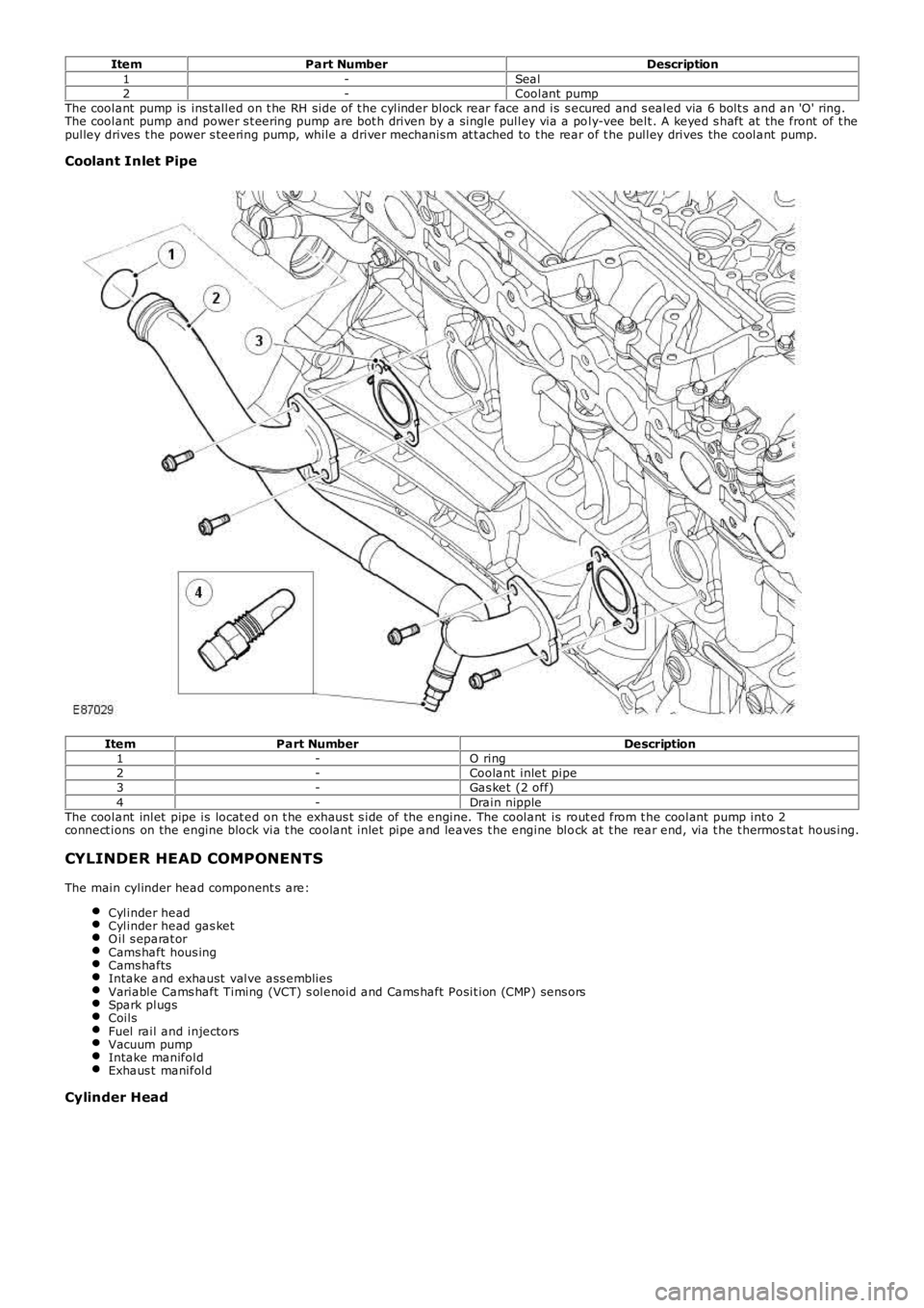
ItemPart NumberDescription1-Seal2-Coolant pumpThe coolant pump is ins t alled on t he RH side of t he cylinder block rear face and is s ecured and s ealed via 6 bolt s and an 'O' ring.The coolant pump and power s t eering pump are bot h driven by a single pulley via a poly-vee belt . A keyed s haft at the front of t hepulley drives t he power s teering pump, while a driver mechanism at t ached to t he rear of t he pulley drives the coolant pump.
Coolant Inlet Pipe
ItemPart NumberDescription1-O ring2-Coolant inlet pipe3-Gas ket (2 off)4-Drain nippleThe coolant inlet pipe is locat ed on t he exhaus t s ide of the engine. The coolant is rout ed from t he coolant pump int o 2connect ions on the engine block via t he coolant inlet pipe and leaves t he engine block at t he rear end, via t he t hermos tat hous ing.
CYLINDER HEAD COMPONENTS
The main cylinder head component s are:
Cylinder headCylinder head gas ketO il s eparat orCams haft hous ingCams haftsIntake and exhaust valve ass embliesVariable Cams haft Timing (VCT) s olenoid and Cams haft Posit ion (CMP) sens orsSpark plugsCoilsFuel rail and injectorsVacuum pumpIntake manifoldExhaus t manifold
Cylinder Head
Page 627 of 3229
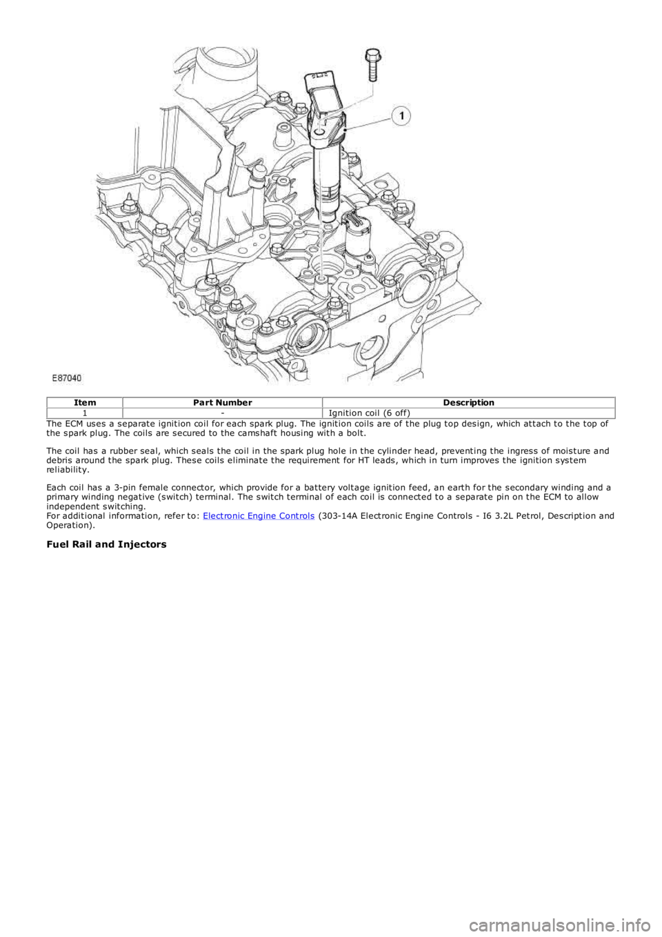
ItemPart NumberDescription1-Ignition coil (6 off)The ECM us es a s eparat e ignit ion coil for each spark plug. The ignit ion coils are of t he plug t op des ign, which at t ach t o t he t op ofthe s park plug. The coils are s ecured to the cams haft hous ing wit h a bolt.
The coil has a rubber seal, which s eals t he coil in the s park plug hole in t he cylinder head, prevent ing t he ingres s of mois t ure anddebris around t he spark plug. Thes e coils eliminat e t he requirement for HT leads , which in turn improves t he ignition s ys t emreliabilit y.
Each coil has a 3-pin female connect or, which provide for a bat tery volt age ignit ion feed, an eart h for t he s econdary winding and aprimary winding negat ive (s wit ch) terminal. The s wit ch t erminal of each coil is connect ed t o a separat e pin on t he ECM to allowindependent s wit ching.For addit ional information, refer t o: Elect ronic Engine Cont rols (303-14A Elect ronic Engine Controls - I6 3.2L Pet rol, Des cript ion andOperation).
Fuel Rail and Injectors
Page 628 of 3229
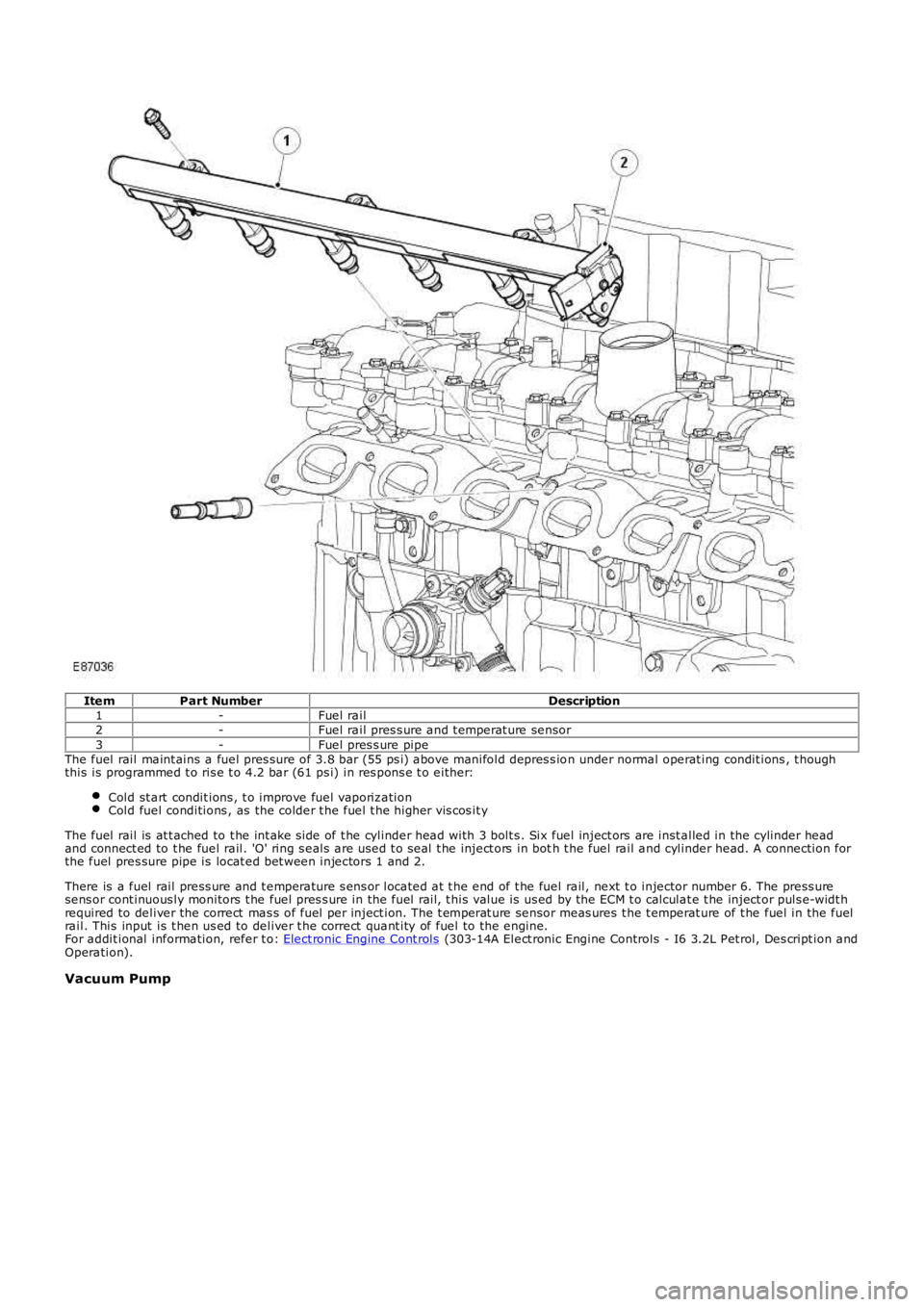
ItemPart NumberDescription1-Fuel rail2-Fuel rail pres s ure and t emperat ure sensor3-Fuel pres s ure pipeThe fuel rail maint ains a fuel pres sure of 3.8 bar (55 ps i) above manifold depres s ion under normal operat ing condit ions , t houghthis is programmed t o ris e t o 4.2 bar (61 ps i) in res pons e t o either:
Cold st art condit ions , t o improve fuel vaporiz ationCold fuel conditions , as the colder t he fuel t he higher vis cos it y
The fuel rail is at t ached to t he int ake s ide of t he cylinder head with 3 bolt s . Six fuel inject ors are inst alled in the cylinder headand connect ed to t he fuel rail. 'O' ring s eals are used t o seal t he inject ors in both t he fuel rail and cylinder head. A connection forthe fuel pres sure pipe is locat ed bet ween injectors 1 and 2.
There is a fuel rail press ure and t emperature s ens or located at t he end of t he fuel rail, next t o injector number 6. The press uresens or cont inuous ly monitors t he fuel pres s ure in the fuel rail, t his value is us ed by the ECM t o calculat e t he inject or puls e-widt hrequired to deliver the correct mas s of fuel per inject ion. The t emperat ure sensor meas ures t he t emperat ure of t he fuel in the fuelrail. This input is t hen us ed to deliver t he correct quant ity of fuel to the engine.For addit ional information, refer t o: Elect ronic Engine Cont rols (303-14A Elect ronic Engine Controls - I6 3.2L Pet rol, Des cript ion andOperation).
Vacuum Pump
Page 793 of 3229
ItemPart NumberDescription
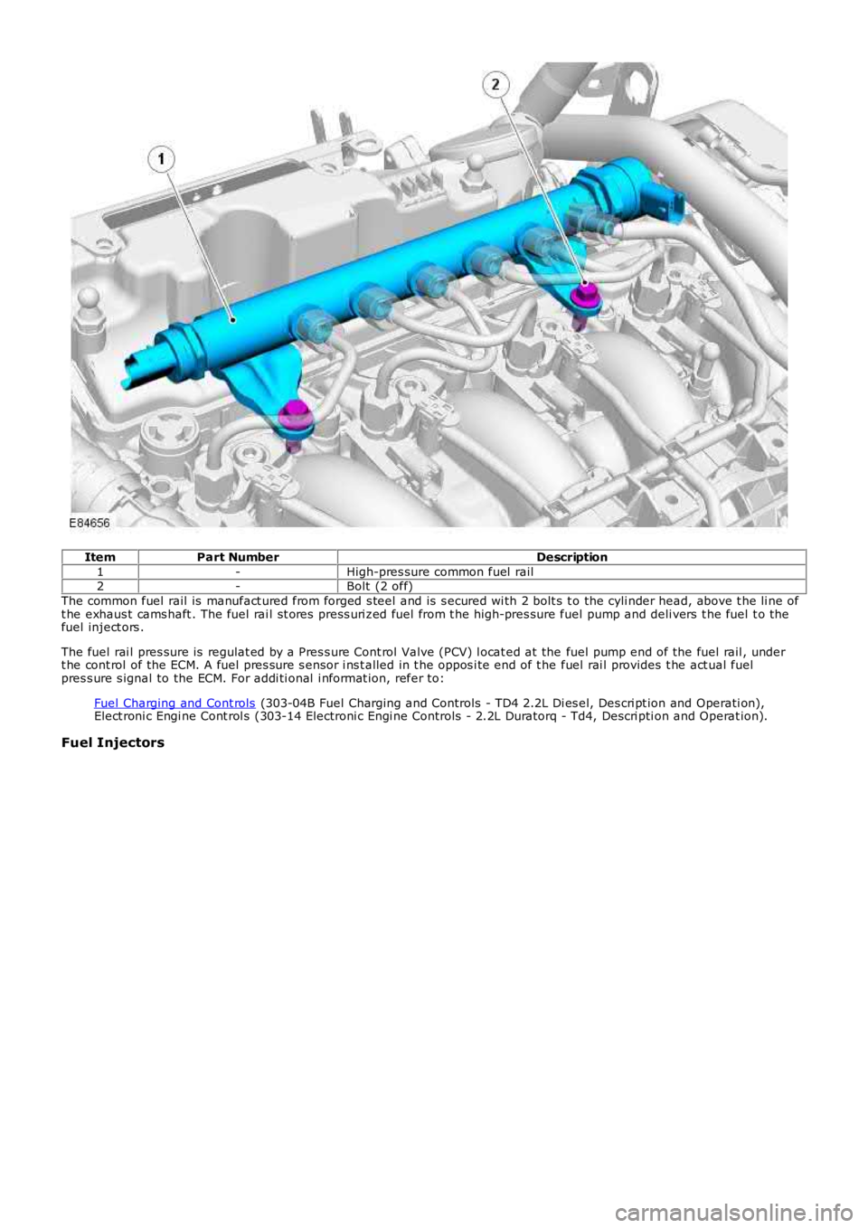
1-High-pres sure common fuel rail2-Bolt (2 off)
The common fuel rail is manufact ured from forged s teel and is s ecured wi th 2 bolt s to the cyli nder head, above t he li ne oft he exhaus t cams haft . The fuel rai l st ores press uri zed fuel from t he high-pres sure fuel pump and deli vers t he fuel t o thefuel inject ors .
The fuel rai l pres sure is regulat ed by a Pres s ure Cont rol Valve (PCV) l ocat ed at the fuel pump end of the fuel rail , undert he cont rol of the ECM. A fuel pres sure s ensor i ns t alled in t he oppos i te end of t he fuel rai l provides t he act ual fuelpres s ure s ignal to the ECM. For addi ti onal i nformat ion, refer to:
Fuel Charging and Cont rols (303-04B Fuel Charging and Controls - TD4 2.2L Di es el, Des cri pt ion and Operati on),Elect roni c Engi ne Cont rol s (303-14 Electroni c Engi ne Controls - 2.2L Duratorq - Td4, Descri pti on and Operat ion).
Fuel Injectors
Page 794 of 3229
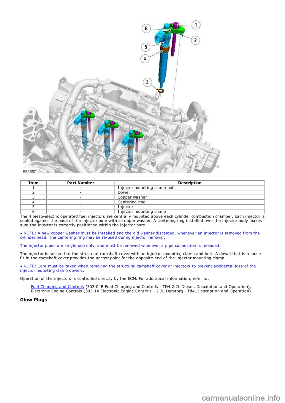
ItemPart NumberDescription
1-Injector mount ing clamp bol t2-Dowel
3-Copper washer
4-Cent ering ring5-Injector
6-Injector mount ing clamp
The 4 pi ezo-el ect ri c operated fuel injectors are cent rall y mounted above each cyl inder combus ti on chamber. Each i njector iss eal ed agai nst the bas e of the injector bore wit h a copper was her. A cent ering ri ng ins tal led over the i njector body makess ure t he i nject or is correct ly pos i ti oned wi thi n t he inject or bore.
• NOTE: A new copper washer mus t be i ns t alled and the ol d was her dis carded, whenever an inject or is removed from t hecyl inder head. The cent eri ng ri ng may be re-us ed duri ng inject or removal.
The inject or pi pes are s i ngl e us e only, and mus t be renewed whenever a pi pe connection is releas ed.
The inject or is s ecured t o t he st ruct ural cams haft cover wit h an i nject or mounti ng cl amp and bolt . A dowel that i s a l oos efi t in the cams haft cover provi des the anchor point for the opposi te end of the i njector mounti ng clamp.
• NOTE: Care must be taken when removi ng the st ruct ural cams haft cover or i njectors to prevent acci dent al los s of theinject or mount ing cl amp dowels .
Operat ion of t he inject ors i s cont rol led direct ly by the ECM. For addi ti onal i nformat ion, refer to:
Fuel Charging and Cont rols (303-04B Fuel Charging and Controls - TD4 2.2L Di es el, Des cri pt ion and Operati on),Elect roni c Engi ne Cont rol s (303-14 Electroni c Engi ne Controls - 2.2L Duratorq - Td4, Descri pti on and Operat ion).
Glow Plugs
Page 975 of 3229
Publi s hed: 11-May-2011
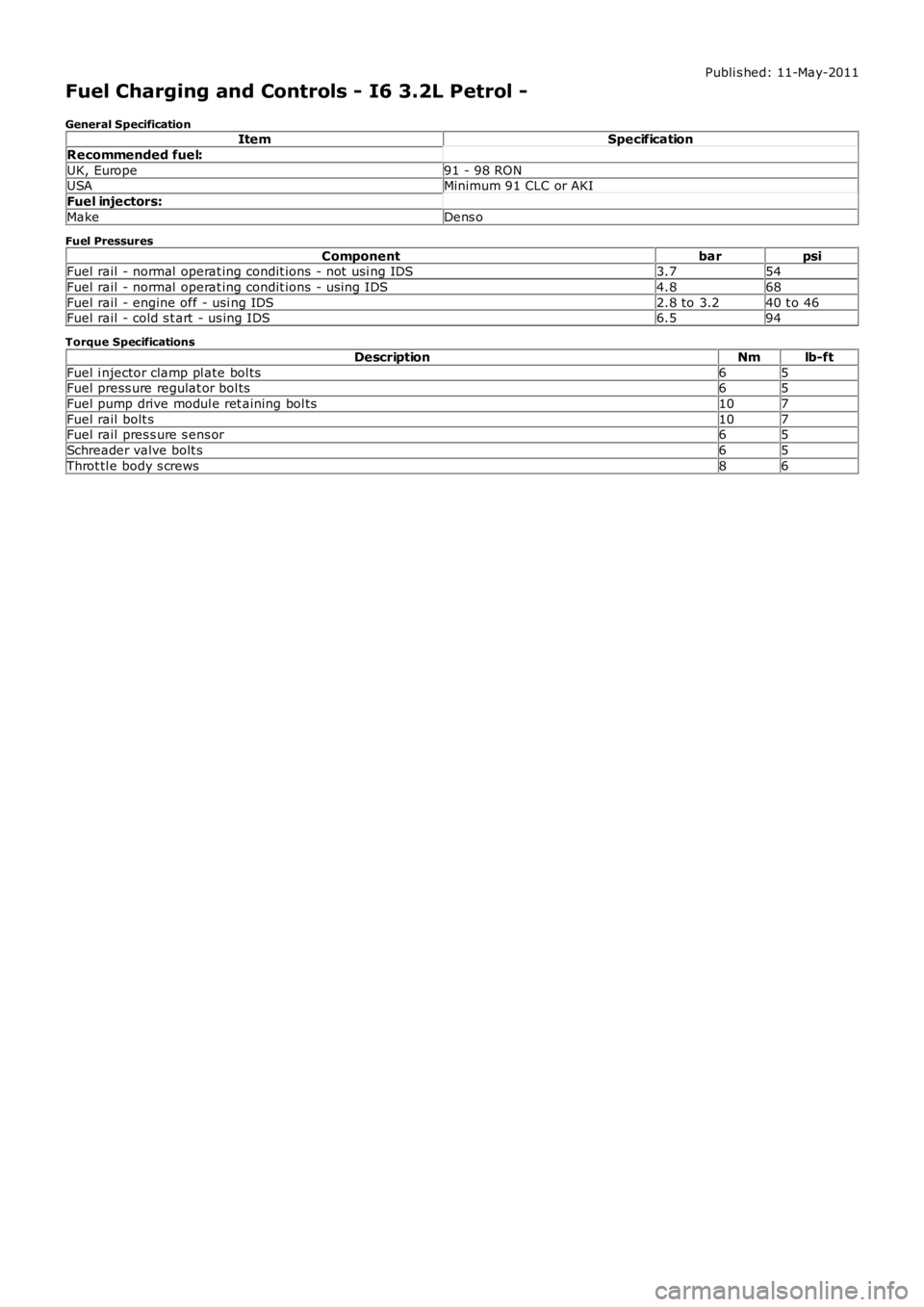
Fuel Charging and Controls - I6 3.2L Petrol -
General SpecificationItemSpecification
Recommended fuel:
UK, Europe91 - 98 RONUSAMinimum 91 CLC or AKI
Fuel injectors:
MakeDens o
Fuel Pressures
ComponentbarpsiFuel rail - normal operat ing condit ions - not usi ng IDS3.754
Fuel rail - normal operat ing condit ions - us ing IDS4.868
Fuel rail - engine off - usi ng IDS2.8 to 3.240 t o 46Fuel rail - cold s t art - us ing IDS6.594
Torque Specifications
DescriptionNmlb-ft
Fuel i njector clamp pl ate bol ts65Fuel press ure regulat or bol ts65
Fuel pump drive modul e ret aining bol ts107
Fuel rail bolt s107Fuel rail pres s ure s ens or65
Schreader valve bolt s65
Throt tl e body s crews86
Page 989 of 3229
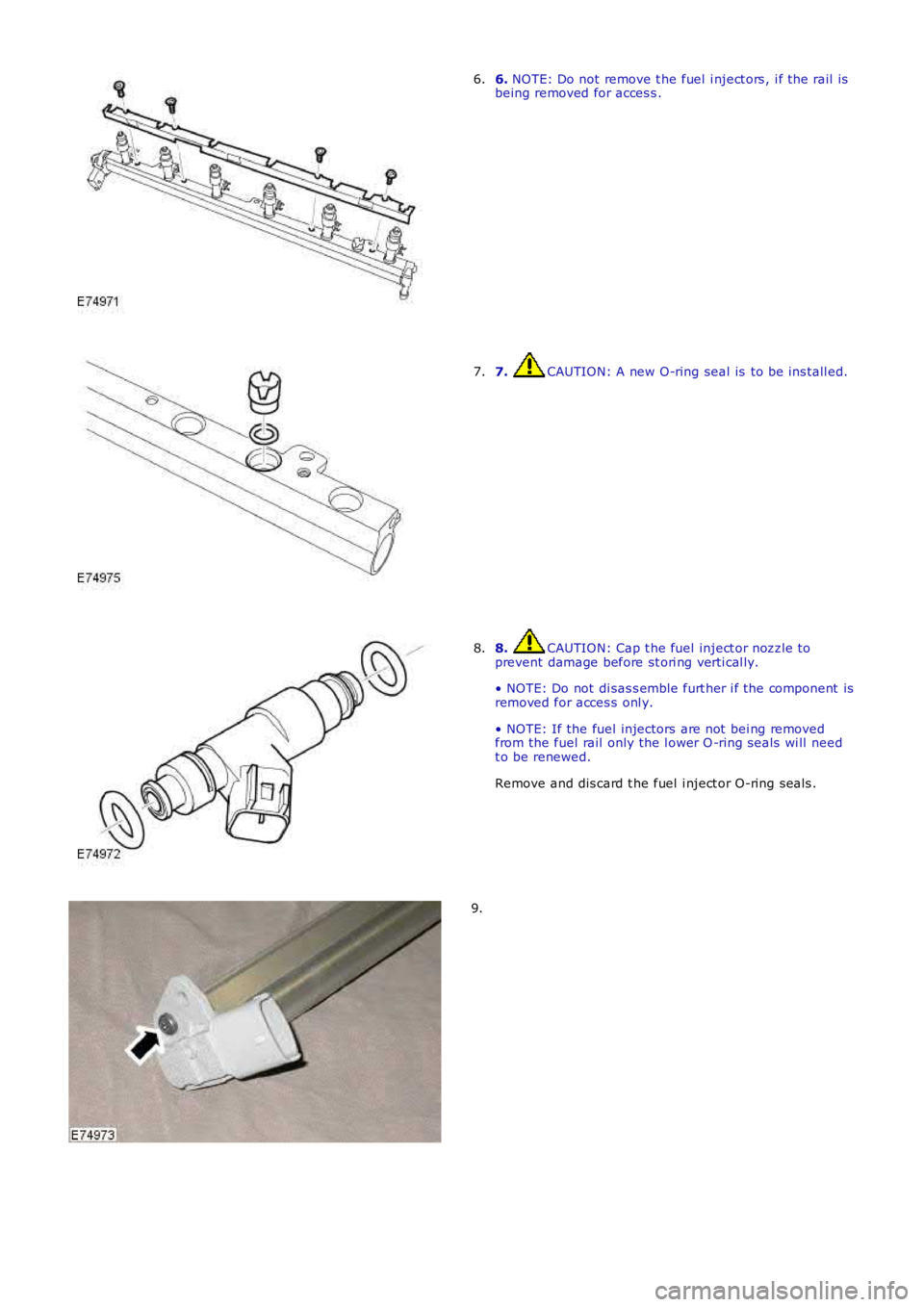
6. NOTE: Do not remove t he fuel i nject ors , i f the rail isbeing removed for acces s .6.
7. CAUTION: A new O-ring seal is to be ins tall ed.7.
8. CAUTION: Cap t he fuel inject or nozzle toprevent damage before st ori ng verti cal ly.
• NOTE: Do not di sas s emble furt her i f the component isremoved for acces s onl y.
• NOTE: If the fuel injectors are not bei ng removedfrom the fuel rail only the l ower O -ring s eals wi ll needt o be renewed.
Remove and dis card t he fuel i nject or O-ring seals .
8.
9.
Page 994 of 3229
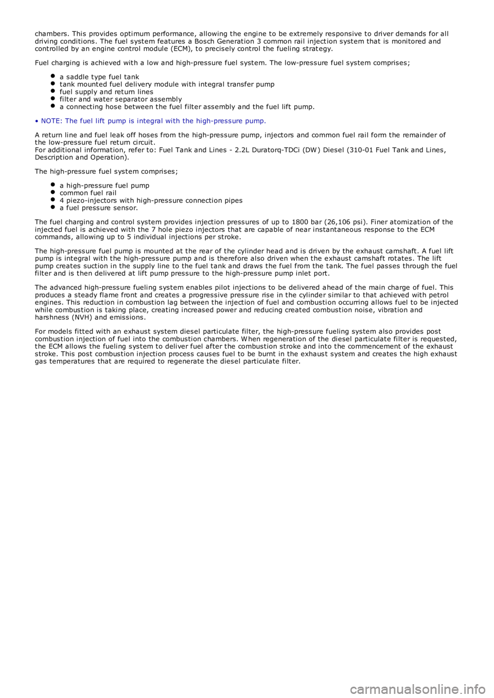
chambers. Thi s provides opti mum performance, all owing t he engi ne t o be extremely respons ive t o dri ver demands for al ldri vi ng condi ti ons . The fuel s yst em features a Bos ch Generat ion 3 common rai l injection s yst em that is moni tored andcont rol led by an engine control modul e (ECM), t o precis ely cont rol the fueli ng st rategy.
Fuel charging is achieved wit h a l ow and hi gh-pres sure fuel s yst em. The l ow-pres s ure fuel s ys tem compris es ;
a s addle t ype fuel tankt ank mount ed fuel deli very module wi th int egral trans fer pumpfuel s uppl y and ret urn linesfi lt er and water s eparator as sembl ya connect ing hos e between t he fuel filt er ass embly and the fuel lift pump.
• NOTE: The fuel l ift pump is i ntegral wi th the hi gh-pres s ure pump.
A return li ne and fuel leak off hos es from the hi gh-pres s ure pump, i nject ors and common fuel rai l form t he remai nder oft he low-pres sure fuel ret urn ci rcuit .For addit ional informat ion, refer t o: Fuel Tank and Lines - 2.2L Duratorq-TDCi (DW ) Dies el (310-01 Fuel Tank and Li nes ,Des cript ion and Operat ion).
The high-press ure fuel s ys t em compri s es ;
a hi gh-pres sure fuel pumpcommon fuel rail4 pi ezo-injectors wit h hi gh-pres s ure connecti on pipesa fuel press ure sens or.
The fuel charging and control s ys tem provides i nject ion press ures of up to 1800 bar (26,106 psi ). Fi ner at omizati on of theinject ed fuel is achieved wi th the 7 hol e piezo i njectors that are capable of near ins tant aneous res ponse to the ECMcommands , all owing up to 5 individual inject ions per st roke.
The high-press ure fuel pump i s mounted at t he rear of t he cyl inder head and i s dri ven by the exhaust cams haft . A fuel l iftpump i s int egral wit h t he high-pres s ure pump and is therefore al so driven when t he exhaus t cams haft rot ates . The li ftpump creat es suct ion i n the supply line to t he fuel t ank and draws t he fuel from the t ank. The fuel pas s es through the fuelfi lt er and is t hen delivered at lift pump pres s ure to the hi gh-pres sure pump i nlet port .
The advanced high-press ure fueli ng s ys t em enables pil ot inject ions to be delivered ahead of t he main charge of fuel. Thisproduces a s teady fl ame front and creates a progres s ive pres s ure ris e in t he cyl inder s imi lar to that achi eved wit h petrolengi nes. This reduct ion i n combust ion lag between t he i nject ion of fuel and combus tion occurring al lows fuel t o be i njectedwhil e combus t ion i s t aki ng place, creat ing i ncreas ed power and reducing creat ed combus t ion nois e, vibrat ion andhars hnes s (NVH) and emis s ions .
For model s fi tt ed wi th an exhaus t sys t em dies el parti cul ate fil ter, the hi gh-pres s ure fueling sys tem als o provi des pos tcombus t ion i njecti on of fuel into the combus ti on chambers. W hen regenerati on of the di esel part iculat e fi lt er is reques t ed,t he ECM all ows the fueli ng s ys t em t o deli ver fuel after t he combus t ion s troke and int o t he commencement of the exhausts troke. This pos t combus t ion i njecti on proces s caus es fuel to be burnt in the exhaust s ys tem and creates t he high exhaus tgas temperatures that are required to regenerate t he dies el part icul ate fi lt er.
Page 996 of 3229
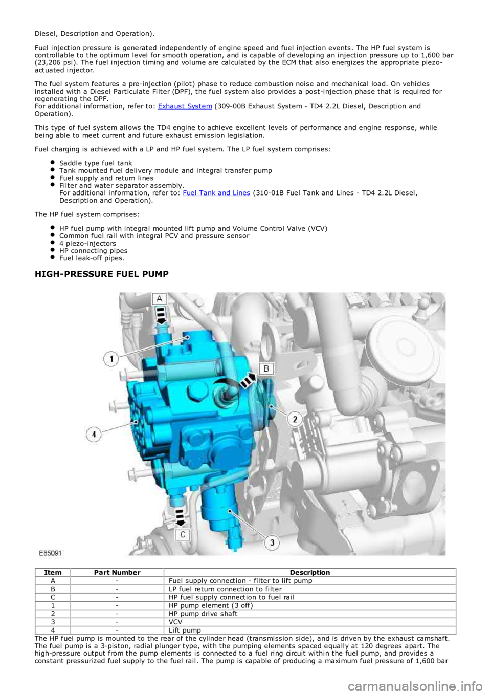
Dies el, Des cript ion and Operat ion).
Fuel i njecti on pres sure is generat ed i ndependent ly of engine s peed and fuel inject ion events . The HP fuel s ys tem iscont rol lable t o t he opti mum level for smoot h operat ion, and is capabl e of devel opi ng an i nject ion press ure up t o 1,600 bar(23,206 psi ). The fuel i njecti on ti ming and vol ume are cal cul at ed by t he ECM t hat als o energizes t he appropriat e piezo-act uated i njector.
The fuel s yst em features a pre-inject ion (pilot ) phas e t o reduce combus ti on noi s e and mechani cal load. On vehiclesins t al led wi th a Di es el Part iculate Fi lt er (DPF), t he fuel s ys tem als o provides a pos t -i nject ion phas e t hat is requi red forregenerat ing t he DPF.For addit ional informat ion, refer t o: Exhaus t Sys t em (309-00B Exhaus t Syst em - TD4 2.2L Di es el, Des cri pt ion andOperat ion).
This t ype of fuel sys t em all ows t he TD4 engi ne t o achi eve excellent l evels of performance and engine res pons e, whilebeing able to meet current and fut ure exhaus t emi s si on legis l at ion.
Fuel charging is achieved wit h a LP and HP fuel s ys t em. The LP fuel s yst em compris es:
Saddl e t ype fuel tankTank mount ed fuel deli very module and integral t rans fer pumpFuel s upply and return li nesFil ter and water s eparator as s embly.For addit ional informat ion, refer t o: Fuel Tank and Lines (310-01B Fuel Tank and Lines - TD4 2.2L Dies el ,Des cript ion and Operat ion).
The HP fuel s ys tem compris es :
HP fuel pump wit h int egral mounted l ift pump and Volume Cont rol Valve (VCV)Common fuel rail wi th integral PCV and press ure s ens or4 pi ezo-injectorsHP connect ing pipesFuel l eak-off pipes .
HIGH-PRESSURE FUEL PUMP
ItemPart NumberDescription
A-Fuel supply connect ion - fil ter t o l ift pumpB-LP fuel return connecti on t o fi lt er
C-HP fuel s upply connect ion to fuel rail
1-HP pump element (3 off)2-HP pump dri ve s haft
3-VCV
4-Li ft pumpThe HP fuel pump is mount ed to the rear of t he cylinder head (t rans mi ss ion si de), and is driven by t he exhaus t cams haft.The fuel pump i s a 3-pis ton, radi al pl unger type, wit h t he pumping el ement s s paced equall y at 120 degrees apart. Thehigh-press ure out put from t he pump el ement s i s connected t o a fuel ri ng ci rcuit wi thi n t he fuel pump, and provi des acons t ant press uri zed fuel s upply to the fuel rail . The pump is capable of producing a maxi mum fuel pres sure of 1,600 bar
Page 998 of 3229
C-HP pipe connecti on – fuel rail t o inject or (4 off)
1-Fuel rail
2-PCV3-Fuel rail press ure sens or
The fuel rai l is manufact ured from forged st eel and secured t o t he cyl inder head with 2 fixings . The fuel rai l st orespres s urized fuel from t he HP pump, and prevent s pres s ure fluct uat ions i n the HP s ys tem. A fuel rail pres s ure s ens or and aPW M PCV are ins tall ed int o t he bore at each end of the fuel rail . The pres s ure s ensor i s ins tal led at t he acces sory dri veend of the fuel rail ; the PCV ins tal led at t he transmis s ion end of t he fuel rai l.
High-pres sure fuel pipes connect t he fuel rai l t o t he HP pump and fuel inject ors . A l eak-off pipe connect s the fuel rail t ot he fuel fi lt er return circui t.
The common fuel rail, fuel press ure s ens or and PCV form an int egral as s embly, and mus t not be separat ed. If a faultoccurs that requires component renewal, t hen t he compl ete fuel rail as s embl y mus t be renewed.
Fuel Rail Pressure Sensor
The fuel rai l pres sure s ens or is mount ed i n t he end of the fuel rail (access ory drive end) and connected to t he ECM vi a t heengi ne harnes s. The press ure sens or is provi ded wit h a 5V power s upply, ground and signal connect ions . The fuel railpres s ure s ensor i s a pi ezo-res is ti ve type s ens or contai ni ng an actuati ng diaphragm. Deflect ion of t he diaphragm provides aproport ional si gnal (output) volt age t o t he ECM, dependant on t he fuel pres s ure wit hin t he fuel rai l.
Pressure Sensor ParametersPressure Sensor Output VoltageFuel Rail Pressure
0.5V230 bar (3,336 ps i)
4.5V1,600 bar (23,206 ps i)The ECM compares t he s ens or s ignal vol tage t o s tored memory val ues, i n order t o cal cul ate the actual fuel pres s urepres ent in t he fuel rail. The ECM then us es t he fuel rai l press ure informat ion t o cont rol t he operati ng posi ti on of the VCVand PCV.For addit ional informat ion, refer t o: Electroni c Engi ne Controls - 2.2L Dies el (303-14 El ect ronic Engine Cont rols - 2.2LDies el, Des cript ion and Operat ion).
Pressure Control Valve (PCV)
The PCV i s mounted i n t he end of the fuel rail (trans mi s si on end) and connect ed t o the ECM via t he engine harnes s . ThePCV i s a s olenoid-operat ed valve cont rol led by a 12V PW M si gnal . The ECM operat es the PCV to adjus t t he fuel pres s urewit hin the fuel rail . Rel ieved fuel is direct ed through t he fuel rail leak-off pipe t o t he fuel fi lt er ret urn circui t. The l eak-offfuel als o provi des cooli ng and lubricat ion for t he PCV.For addit ional informat ion, refer t o: Electroni c Engi ne Controls - 2.2L Dies el (303-14 El ect ronic Engine Cont rols - 2.2LDies el, Des cript ion and Operat ion).
The PCV i s normall y open when t he s ol enoi d is not energi zed by the ECM. The resi s tance val ue of the PCV sol enoi d coi l is3.6 ohms at 20°C (68°F).
The PCV i s als o us ed by t he ECM t o provide di rect cont rol of the fuel sys tem, in t he fol lowi ng si tuat ions :
Duri ng s udden t rans ient phas es i n engine s peed (s uddenl y li ft ing off the accel erat or pedal, for example) where VCVact ion is not s ufficient to affect t he s uppl y of fuel to the fuel rail .To cont rol fuel press ure in t he event that the VCV fai ls .Duri ng the fuel heat ing period, when supply fuel temperat ure is l ess than 40°C (104°F). The VCV i s ful ly opened byt he ECM and t he HP pump compres s es a maximum quanti ty of fuel t o rais e t he fuel t emperature. The PCV is t henmodulat ed by the ECM to provide l eak-off fuel from the fuel rail t o t he fuel fi lt er ret urn circui t. The fuel i s t henrecircul ated t hrough t he fuel fi lt er and back t o t he HP pump.W hen t he fuel s uppl y t emperature is greater t han 70°C (158°F). The PCV is modul ated by t he ECM t o releas e fuelrai l pres sure, s ubs equentl y decreasi ng the fuel temperat ure to protect the fuel sys tem component s. Leak-off fuelfrom the fuel rail is direct ed to the fuel fil ter return ci rcuit and back t o the fuel tank.Duri ng engi ne s hut down t o progres s ively coll aps e fuel rail pres s ure.
FUEL INJECTORS