fan LAND ROVER FRELANDER 2 2006 Repair Manual
[x] Cancel search | Manufacturer: LAND ROVER, Model Year: 2006, Model line: FRELANDER 2, Model: LAND ROVER FRELANDER 2 2006Pages: 3229, PDF Size: 78.5 MB
Page 16 of 3229
Woodruff keys
W oodruff keys may be reus ed provided t here i s no i ndi cat ion of wear or dis torti on.
Remove any burrs from edges of keyways us ing a fine fil e.
Split pins
Never at tempt t o s t raight en and reus e a s pli t pin, always make s ure that repl acement pins are of the correct si ze for t hehole i n which t hey are to be ins tal led.
Screw Threads
Damaged nuts , bolt s and s crews mus t always be dis carded. Att empti ng to recut or repai r damaged threads wi th at ap or di e i mpai rs the s t rength and fi t of t he t hreads and is not recommended.
• NOTE: Duri ng cert ai n repai r operat ions , it may be neces sary t o remove t races of t hread locking agent s us ing a tap.W here thi s is neces sary, t he i ns t ructi on to do s o wi ll appear in the relevant operation and it i s ess enti al that a t ap of thecorrect s ize and t hread i s used.
Some bolt s are coat ed wit h a thread locki ng agent and unles s s tat ed otherwis e, they mus t not be reus ed. Newbolt s havi ng the same part number as the original mus t always be i nst all ed. W hen nuts or bolt s are to bedis carded, t he repai r operat ion and relevant torque chart will i ncl ude an ins truct ion to that effect . Do not usepropri etary thread locki ng agent s as t hey may not meet the specificati on required. See al so Encapsul at ed('Patched') Bol ts and Screws.Always make s ure that repl acement nuts and bol ts are at leas t equal i n s trengt h t o thos e t hat they are repl acing.Cast ell ated nut s mus t not be loosened t o accept a s pli t pin except in recommended cas es when thi s forms part ofan adjus tment .Do not all ow oil or greas e t o enter bli nd holes , the hydrauli c acti on res ult ing from ti ght ening t he bolt or s tud cans plit t he housi ng and als o gi ve a fal s e torque reading.Always t ighten a nut, bolt or s crew to t he s peci fi ed torque fi gure, damaged or corroded threads can give a fals et orque reading.Nut and bolt loos ening and t ightening sequences , where gi ven, mus t ALW AY S be foll owed. Di st ort ion ofcomponents or fault y s eal ing of joints wil l res ul t if t he s equences are not fol lowed. W here an ins t ructi on is gi ven tot ighten i n s tages , thes e s tages mus t be adhered t o; do not at t empt to combi ne st ages part icul arl y where cert ains tages involve t ight eni ng by degrees.To check or re-t ighten a fi xing t o a s peci fi ed t orque, firs t loosen a quart er of a turn, t hen ret ighten to the s peci fi edt orque fi gure.Unles s ins t ructed ot herwis e, do not lubricat e bolt or nut t hreads pri or t o i nst all ing.
W here it i s s tat ed t hat bolt s and s crews may be reus ed, t he fol lowi ng procedures must be carri ed out:
Check t hat threads are undamaged.Remove all t races of locki ng agent from the threads .
CAUTION: DO NOT us e a wi re brus h; take care t hat threads are not damaged.
Make s ure t hat threads are clean and free from oil or greas e.Apply t he s pecified locki ng agent t o t he bolt t hreads .
Bolt and Nut Identification
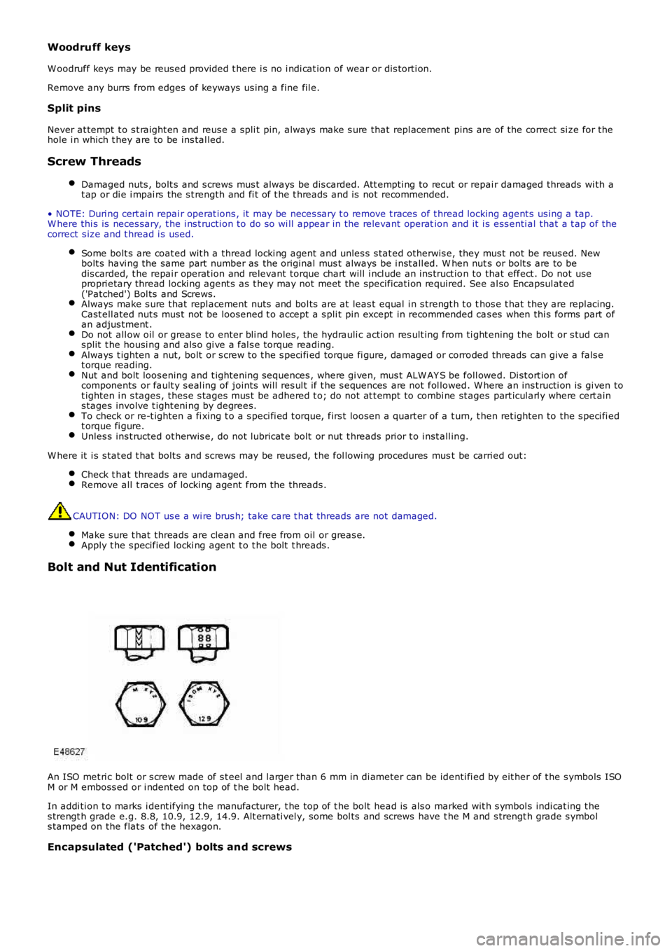
An ISO met ri c bolt or s crew made of s t eel and l arger than 6 mm in di ameter can be identi fi ed by eit her of t he s ymbols ISOM or M emboss ed or i ndent ed on top of t he bolt head.
In addi ti on t o marks i dent ifying t he manufacturer, t he top of t he bolt head is als o marked wit h s ymbol s indi cat ing t hes trengt h grade e.g. 8.8, 10.9, 12.9, 14.9. Alt ernati vel y, some bol ts and screws have t he M and s trengt h grade s ymbols tamped on the flat s of the hexagon.
Encapsulated ('Patched') bolts and screws
Page 92 of 3229

DT CDescriptionPossible CauseAction
ins tal lati on of a new modul e/component
P0032-12HO2S Heater Control CircuitHigh (Bank 1, Sens or 1) -Circui t s hort to bat t ery
• NO TE: - Ci rcuit O_T_SHT1 -
Front heated oxygens ensor heater cont rolcircui t s hort ci rcuit t opowerFront heated oxygens ensor failure
Refer to the el ect ri cal circui t diagramsand check front heat ed oxygen s ensorheat er cont rol ci rcuit for short ci rcuit t opowerCheck and i ns t all a new front heatedoxygen s ens or as requi red. Refer to thewarrant y poli cy and procedures manual,or det ermi ne if any prior approvalprogramme is in operat ion, pri or t o t heins tal lati on of a new modul e/component
P0045-13Turbo charger/SuperchargerBoost Cont rol A Ci rcuit /Open - Circui t open
• NO TE: - Ci rcuit O_T_BPANEG -
Vari able geometryt urbocharger actuat or vanecircui t open ci rcuit
Refer to the el ect ri cal circui t diagramsand check variabl e geomet ryturbocharger act uator vane ci rcuit foropen ci rcuitCarry out t he pinpoint t est s as s oci at edwit h t his DTC us ing the manufact urerapproved di agnos ti c s ys t em
P0045-18Turbo charger/SuperchargerBoost Cont rol A Ci rcuit /Open - Circui t current belowt hreshol d
Power s tage t emperaturedependant currentl imi tat ion
Refer to the el ect ri cal circui t diagramsand check connecti ons are s ecure andwiring i ntegri tyCarry out t he pinpoint t est s as s oci at edwit h t his DTC us ing the manufact urerapproved di agnos ti c s ys t em
P0045-19Turbo charger/SuperchargerBoost Cont rol A Ci rcuit /Open - Circui t current abovet hreshol d
• NO TE: - Ci rcuit O_T_BPAPOS -
Actuat or-vane vari abl egeometry t urbocharger -Power s tage output 1(pos i ti ve) s hort circui t topowerTurbo charger actuatorpower s tage output 1circui t over current
• NOTE: Thi s DTC may be logged due t o batt eryvol tage. Check t he body cont rol module,informati on and entertainment module andnavi gat ion s ys tem module for relat ed DTC's . IfDTC's are logged s us pect generat or or bat terysupply vol tage faul t. Check and repair asrequired pri or t o di agnos ing t his DTC
Usi ng t he manufacturer approveddiagnos t ic s yst em perform t he (T urbo,exhaust gas recirculation and air pathdynamic test) rout ineRefer to the el ect ri cal circui t diagramsand check t he act uat or vane variablegeomet ry turbocharger ci rcuit -O_T_BPAPOS - For s hort circuit t o power
P0046-19Turbo charger/SuperchargerBoost Cont rol A Ci rcuitRange/Performance - Circui tcurrent above threshold
Power s tage exces st emperatureVari able geometryt urbocharger actuat or vanecircui t, s hort circui t toground, s hort circuit t opowerVari able geometryt urbocharger actuat or vanefailure
Refer to the el ect ri cal circui t diagramsand check t he variable geomet ryturbocharger act uator vane ci rcuit , forshort ci rcuit t o ground, s hort circuit t opowerCheck and i ns t all a new variablegeomet ry turbocharger act uat or vane asrequired. Refer t o t he warranty pol icyand procedures manual , or det ermi ne ifany prior approval programme is i noperati on, prior to the i nst all ati on of anew module/componentCarry out t he pinpoint t est s as s oci at edwit h t his DTC us ing the manufact urerapproved di agnos ti c s ys t em
P0047-11Turbo charger/SuperchargerBoost Cont rol A Ci rcuit Low -Circui t s hort to ground
• NO TE: - Ci rcuit O_T_BPAPOS -
Vari able geometryt urbocharger actuat or vanecircui t s hort ci rcuit t oground
Refer to the el ect ri cal circui t diagramsand check t he variable geomet ryturbocharger act uator vane ci rcuit , forshort ci rcuit t o groundCarry out t he pinpoint t est s as s oci at edwit h t his DTC us ing the manufact urerapproved di agnos ti c s ys t em
P0047-14Turbo charger/SuperchargerBoost Cont rol A Ci rcuit Low -Circui t s hort to ground oropen
• NO TE: - Ci rcuit O_T_BPANEG -
Vari able geometryt urbocharger actuat or vanecircui t s hort ci rcuit t oground, open ci rcuit
Refer to the el ect ri cal circui t diagramsand check t he variable geomet ryturbocharger act uator vane ci rcuit , forshort ci rcuit t o ground, open ci rcuitCarry out t he pinpoint t est s as s oci at edwit h t his DTC us ing the manufact urerapproved di agnos ti c s ys t em
P0047-18Turbo charger/SuperchargerBoost Cont rol A Ci rcuit Low -Circui t current belowt hreshol d
Power s tage currentl imi tat ionRefer to the el ect ri cal circui t diagramsand check connecti ons are s ecure andwiring i ntegri tyCarry out t he pinpoint t est s as s oci at edwit h t his DTC us ing the manufact urerapproved di agnos ti c s ys t em
Page 105 of 3229
DT CDescriptionPossible CauseAction
B1038-01Left front s eat heaters ens or general fail ureinformat ion - Generalelectrical fail ure
Sens or damaged, opencircuitRefer t o t he electrical ci rcuit diagrams and checkfront left s eat heater s ensor circui t for open circuit
B103A-01Right front seat heaters ens or general fail ureinformat ion - Generalelectrical fail ure
Sens or damaged, opencircuitRefer t o t he electrical ci rcuit diagrams and checkfront ri ght seat heater s ens or circui t for opencircui t
B105A-11Cabi n t emperature s ensorfan general electricalfai lures - Ci rcuit s hort t oground
In-vehi cl e t emperatures ens or circuit - short toground
Refer t o t he electrical ci rcuit diagrams and checkIn-vehicle t emperat ure s ens or circui t for s hort t oground
B105A-15Cabi n t emperature s ensorfan general electricalfai lures - Ci rcuit s hort t obatt ery or open
In-vehi cl e t emperatures ens or circuit - short topower or open circui t
Refer t o t he electrical ci rcuit diagrams and checkIn-vehicle t emperat ure s ens or for short to power oropen circui t
B105A-71Cabi n t emperature s ensorfan general electricalfai lures - Act uat or s tuck
Fan jammed or brokenRemove obs truct ion from fan. Ins t all new s ensoras requi red
B1081-09Left t emperature dampermot or general fai lureinformat ion - Componentfai lures
Int ernal fai lureInst all a new act uat or as required
B1081-77Left t emperature dampermot or mechanical fail ures -Commanded pos i ti on notreachabl e
Obs truct ion i n flapmovementRange greater t hanexpected defaul t
Cl ear obs truct ion from fl ap. Usi ng manufacturerapproved diagnost ic s ys tem check rel evantdatal ogger s ignals t o read motor range andcompare defaul ts . Execut e LIN cal ibrat ion run us ingmanufact urer approved di agnos ti c s ys t emB1081-87Left t emperature dampermot or bus s ignal/mes s agefai lures - Mis s ing mes s age
LIN Bus faultAct uator faul tRefer t o t he electrical ci rcuit diagrams and checkt he left air t emperature door motor LIN Bus ci rcuit ,power and ground s uppl y circuit s for short ci rcuit t oground, s hort circuit t o power, open circui t, hi ghresi st ance. Inst all a new act uat or as required
B1082-09Right t emperature dampermot or general fai lureinformat ion - Componentfai lures
Int ernal fai lureInst all a new act uat or as required
B1082-77Right t emperature dampermot or mechanical fail ures -Commanded pos i ti on notreachabl e
Obs truct ion i n flapmovementRange greater t hanexpected defaul t
Cl ear obs truct ion from fl ap. Usi ng manufacturerapproved diagnost ic s ys tem check rel evantdatal ogger s ignals t o read motor range andcompare defaul ts . Execut e LIN cal ibrat ion run us ingmanufact urer approved di agnos ti c s ys t em
B1082-87Right t emperature dampermot or bus s ignal/mes s agefai lures - Mis s ing mes s age
LIN Bus faultAct uator faul tRefer t o t he electrical ci rcuit diagrams and checkt he ri ght ai r temperature door mot or LIN Buscircui t, power and ground s uppl y circuit s for shortcircui t to ground, s hort circui t t o power, opencircui t, hi gh res is t anceB1083-09Reci rculat ion damper motorgeneral fail ure Informati on- Component failures
Int ernal fai lureInst all new actuat or as required
B1083-77Reci rculat ion damper motormechani cal fai lures -Commanded pos i ti on notreachabl e
Obs truct ion i n flapmovementRange greater t hanexpected defaul t
Cl ear obs truct ion from fl ap. Usi ng manufacturerapproved diagnost ic s ys tem check rel evantdatal ogger s ignals t o read motor range andcompare defaul ts . Execut e LIN cal ibrat ion run us ingmanufact urer approved di agnos ti c s ys t em
B1083-87Reci rculat ion damper motorbus s ignal /mess age fai lures- Mis s ing mess age
LIN Bus faultAct uator faul tRefer t o t he electrical ci rcuit diagrams and checkt he air i nt ake door motor LIN Bus ci rcuit , powerand ground s upply circui ts for s hort circuit toground, s hort circuit t o power, open circui t, hi ghresi st anceB1085-09Defrost er damper mot orgeneral fail ure -Informat ion componentfai lures
Int ernal fai lureInst all new actuat or as required
B1085-77Defrost er damper mot ormechani cal fai lures -Commanded pos i ti on notreachabl e
Obs truct ion i n flapmovementRange greater t hanexpected defaul t
Cl ear obs truct ion from fl ap. Cl ear the DTC andretes t. If the problem pers is ts , remove the defros tvent/regis t er bl end door actuat or and check theblend flap operat ion
B1085-87Defrost er damper mot orbus s ignal /mess age fai lures- Mis s ing mess age
LIN Bus faultAct uator faul tRefer t o t he electrical ci rcuit diagrams and checkt he s creen air dis t ri but ion door mot or LIN Buscircui t, power and ground s uppl y circuit s for shortcircui t to ground, s hort circui t t o power, opencircui t, hi gh res is t ance
B1086-09Air dis t ri but ion dampermot or general fai lure -Informat ion componentfai lures
Int ernal fai lureInst all a new act uat or as required
Page 181 of 3229
Air Filtering
CAUTION: When vehicles are operating under arduous conditions, the following service item must be carried outevery 12 months or 15,000 miles (24,000 km).
Replace the ai r fi lt er el ement.For addit ional informat ion, refer t o: Air Cl eaner (303-12A Int ake Ai r Dis t ri but ion and Fi lt ering - I6 3.2L Petrol ,Removal and Inst all ati on).
Accessory Drive Belt
CAUTION: When vehicles are operating under arduous conditions, the following service item must be carried outevery 5 years or 75,000 miles (120,000 km).
Replace the access ory drive bel t.For addit ional informat ion, refer t o: Acces sory Drive Belt (303-05A Acces s ory Drive - I6 3.2L Pet rol , Removal andIns t allat ion).
Radiator and Cooling Fan
CAUTION: When vehicles are operating under arduous conditions, the following item must be carried out.
Vis uall y check radi at or for external obs truct ions , check cool ing fan blades for damage.
Continuous Use In Severe Off-Road Conditions
CAUTION: After 50 miles (80 km) continuous use in severe off-road conditions i.e. w ading, deep mud andabrasive grit/slurry, the following items must be cleaned and inspected.
The parking brake.The acces sory dri ve belt .
Vehicles used in dusty or field conditions or d eep wading:
More frequent att enti on to the ai r cl eaner wi ll be requi red.
Additional Items That May Require Attention
1. Every 6 years: It i s recommended t hat al l brake fl uid hydrauli c s eal s are replaced.
• NOTE: This i s in addi ti on to the maintenance requirement that fl exi ble brake hos es MUST be replaced at thi s s erviceint erval.
Page 192 of 3229
Ins pect rear pads for wear.
Check brake cal ipers for s igns of fl ui d l eaks .
Check brake dis cs for condi ti on.
Check al l brake boos t er and brake s ys t em pipes and hos es for condi ti on, chafi ng and
leaks.Clean road wheel hub s pigot s and appl y greas e, Land Rover Part Number RY L 105020 t o
t he wheel mat ing surface
of each s pigot . Brake Fluid Replacement
CAUTION:
When vehicles are operating under arduous conditions, the following service item mus t be carried out
every 2 Years or 30,000 miles (48,000 km).
Replace brake fluid. Road Wheel Speed Sensors
CAUTION:
When vehicles are operating under arduous conditions, the following service item mus t be carried out
every 3 months or 3,750 miles (6,000 km).
Ins pect the road wheel s peed s ens or harness es for damage. Engine Oil and Filter
• CAUTIO NS:
When vehicles are operating under arduous conditions, the following service item mus t be carried out every 3
months or 3,750 miles (6,000 km).
Vehicles operating on high sulphur content fuel - above 0.7%, the oil and filter cha nge period MUST NOT
exceed 3 months or 3,750 miles (6,000 km).
Vehicles operating on moderate sulphur content fuel - 0.3 to 0.7%, the oil and filte r change period MUST NOT
exceed 6 months or 7,500 miles (12,000 km).
Renew engi ne oil and fil ter. Air Filtering
CAUTION:
When vehicles are operating under arduous conditions, the following service item mus t be carried out
every 12 months or 15,000 miles (24,000 km).
Replace the ai r fi lt er el ement.
For addit ional informat ion, refer t o: Air Cl eaner (303-12A Int ake Ai r Dis t ri but ion and Fi lt ering - I6 3.2L Petrol ,
Removal and Inst all ati on). Accessory Drive Belt
CAUTION:
When vehicles are operating under arduous conditions, the following service item mus t be carried out
every 5 years or 75,000 miles (120,000 km).
Replace the access ory drive bel t. For addi ti onal informat ion, refer to: Acces s ory Drive Belt (303-05A Acces s ory Drive
- I6 3.2L Pet rol, Removal and Ins tal lat ion). Camshaft Timing Belt, Tensioner and Pulley
CAUTION:
When vehicles are operating under arduous conditions, the following service item mus t be carried out
every 4 years or 60,000 miles (96,000 km).
Replace the cams haft t iming belt , tens ioner and pul ley.
For addit ional informat ion, refer t o: Timi ng Belt (303-01B Engi ne - TD4 2.2L Dies el, Removal and Inst all ati on).
Radiator/Charge Air Cooler and Cooling Fan
CAUTION:
When vehicles are operating under arduous conditions, the following items must be ca rried out.
Vis uall y check t he radiat or/charge air cool er for ext ernal obst ruct ions, check cooli ng fan bl ades for damage.Remove any debris from t he charge air cool er us i ng a l ow pres s ure hos e.
Continuous Use In Severe Off-Road Conditions
CAUTION:
After 50 miles (80 km) continuous use in severe off-road conditions i.e. w ading, dee p mud and
abrasive grit/slurry, the following items must be cleaned and inspected.
Page 660 of 3229
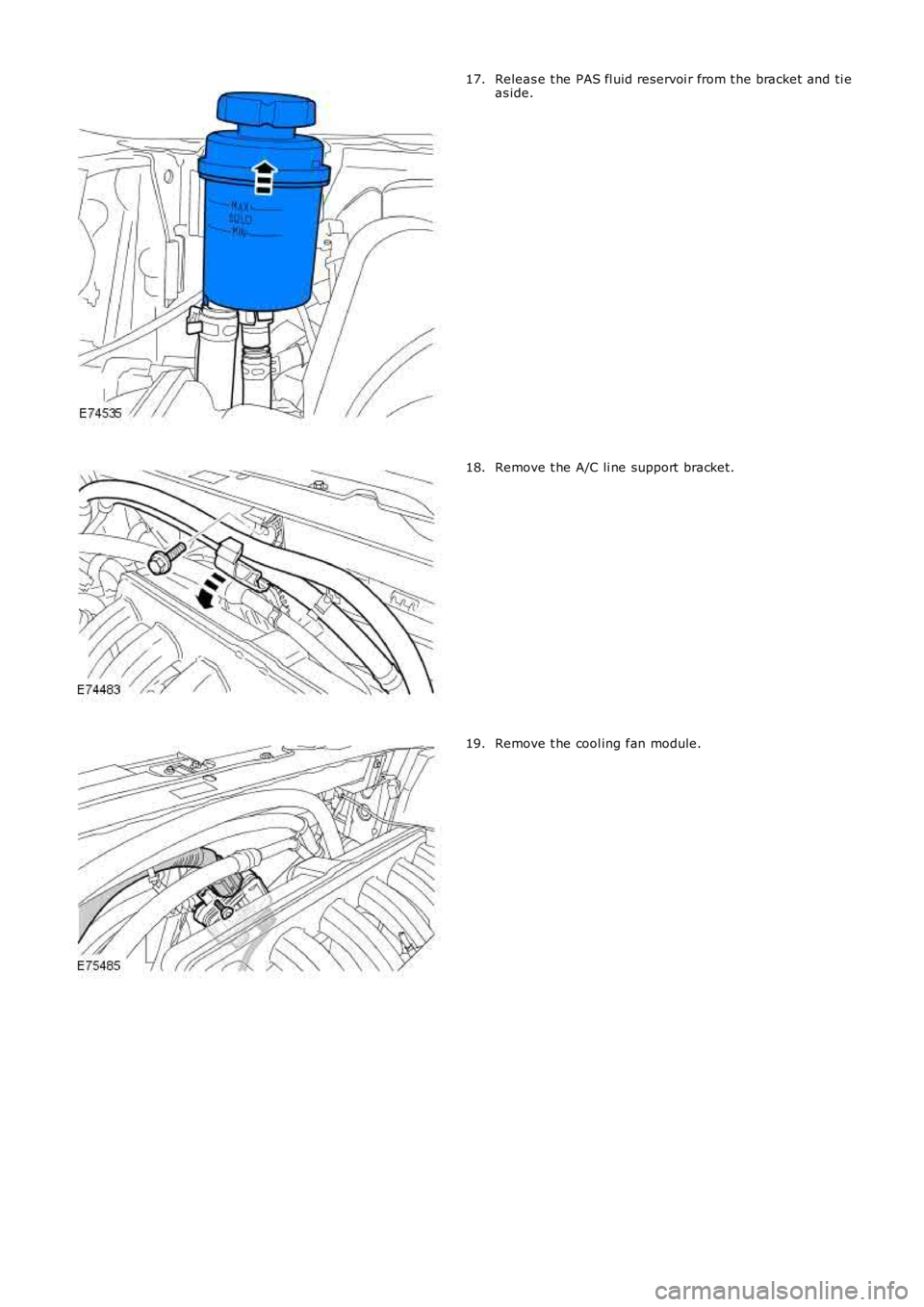
Releas e t he PAS fl uid reservoi r from t he bracket and ti eas ide.17.
Remove t he A/C li ne support bracket.18.
Remove t he cool ing fan module.19.
Page 663 of 3229
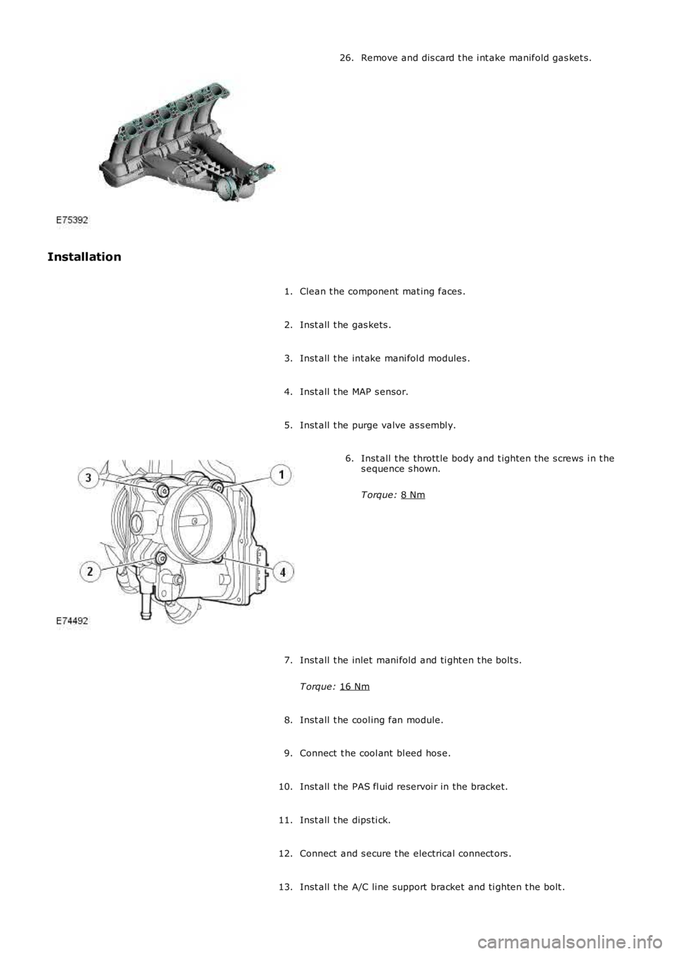
Remove and dis card t he i nt ake manifold gas ket s .
26.
Installation Clean t he component mat ing faces .
1.
Inst all t he gas kets .
2.
Inst all t he int ake mani fol d modules .
3.
Inst all t he MAP s ensor.
4.
Inst all t he purge valve as s embl y.
5. Inst all t he thrott le body and t ighten the s crews i n t he
s equence s hown.
T orque: 8 Nm 6.
Inst all t he inlet mani fold and ti ght en t he bolt s.
T orque: 16 Nm 7.
Inst all t he cool ing fan module.
8.
Connect t he cool ant bl eed hos e.
9.
Inst all t he PAS fl uid reservoi r in the bracket.
10.
Inst all t he dips ti ck.
11.
Connect and s ecure t he electrical connect ors .
12.
Inst all t he A/C li ne support bracket and ti ghten t he bolt .
13.
Page 741 of 3229
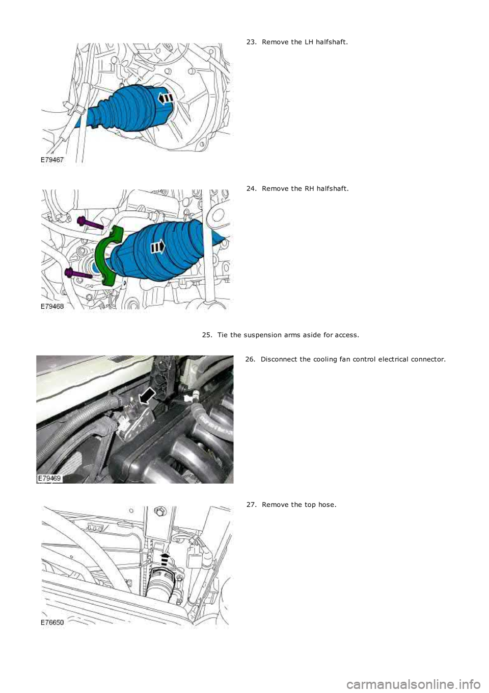
Remove t he LH halfshaft.23.
Remove t he RH halfs haft.24.
Tie the s us pens ion arms as ide for acces s.25.
Dis connect the cooli ng fan control elect rical connect or.26.
Remove t he top hos e.27.
Page 749 of 3229
Stage 1:
Stage 2:
T orque:
40 Nm Inst all t he cool ant expans i on tank.
T orque: 10 Nm 8.
Connect t he purge l ine.
9.
Connect t he engi ne compartment ground cables .
T orque: M8 25 Nm M6
10 Nm 10.
Secure t he engi ne wiring harnes s .
T orque: 10 Nm 11.
Inst all t he RH ground cable.
T orque: 10 Nm 12.
13. CAUTIONS: A new O-ri ng s eal i s to be ins tal led.
Ext reme cl eanli ness must be exerci sed when handli ng t hes e
component s.
Connect t he fuel li ne.
13.
Inst all t he transmis si on fluid cooler.
14.
Connect t he cool ant t op hos e.
15.
Connect t he cool ant bot tom hos e.
16.
Connect t he cool ing fan electrical connect or.
17.
Inst all t he RH halfs haft s upport .
T orque: 25 Nm 18.
Inst all t he LH halfshaft.
19.
W it h ass i st ance, i ns t all the hal fs haft t o t he hub.
20.
Inst all t he hal fs haft s .
T orque: 45 Nm 80°21.
Connect t he s el ect or cabl e to the trans mi ss i on.
22.
Connect t he low pres sure li ne t o t he power s t eering pump.
23.
Page 802 of 3229
Publi s hed: 11-May-2011
Engine - TD4 2.2L Diesel - Engine
Diagnosi s and Tes ti ng
Principle of Operation
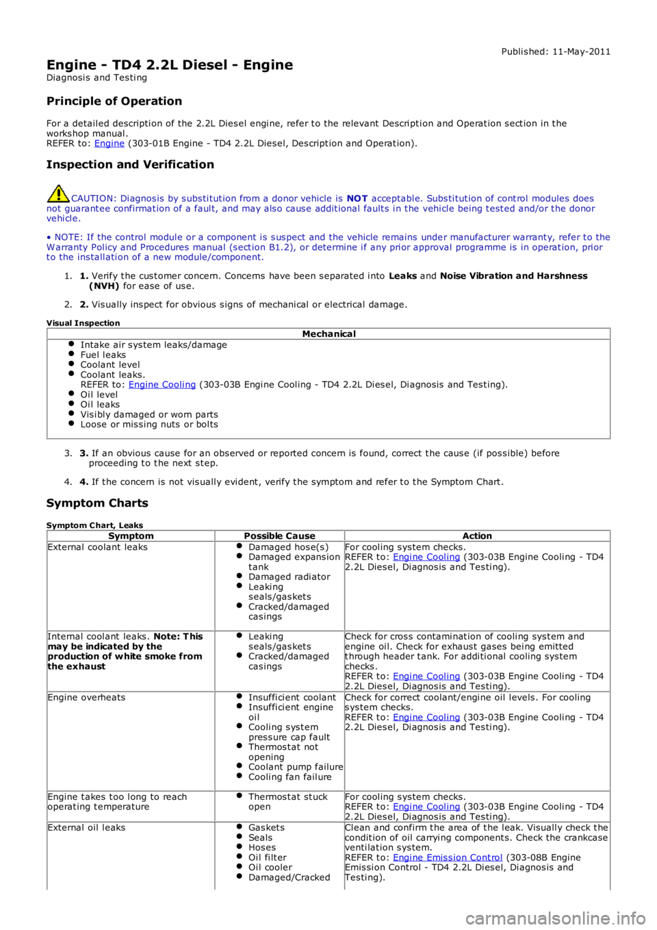
For a detail ed descripti on of the 2.2L Dies el engi ne, refer t o the relevant Descri pti on and Operat ion s ect ion in t heworks hop manual .REFER to: Engine (303-01B Engine - TD4 2.2L Dies el, Des cript ion and Operat ion).
Inspection and Verification
CAUTION: Di agnos is by s ubs ti tut ion from a donor vehicle is NO T acceptabl e. Subs ti tut ion of cont rol modules doesnot guarant ee confirmat ion of a faul t, and may als o caus e addit ional fault s i n t he vehi cl e being t est ed and/or t he donorvehi cl e.
• NOTE: If the control modul e or a component i s s us pect and the vehicle remains under manufacturer warrant y, refer t o theW arranty Pol icy and Procedures manual (s ect ion B1.2), or determine i f any pri or approval programme is in operat ion, pri ort o the ins tall ati on of a new module/component.
1. Verify t he cus t omer concern. Concerns have been s eparated i nto Leaks and Noise Vibration and Harshness(NVH) for ease of us e.1.
2. Vis ually ins pect for obvious s igns of mechani cal or electrical damage.2.
Visual Inspection
MechanicalIntake air s ys tem leaks/damageFuel l eaksCoolant levelCoolant leaks.REFER to: Engine Cooli ng (303-03B Engi ne Cool ing - TD4 2.2L Di es el, Di agnos is and Tes t ing).Oi l levelOi l leaksVis i bl y damaged or worn partsLoose or mis s ing nuts or bol ts
3. If an obvious cause for an obs erved or report ed concern is found, correct t he caus e (if pos s ible) beforeproceeding t o t he next s t ep.3.
4. If t he concern is not vis uall y evi dent , verify t he s ymptom and refer t o t he Symptom Chart .4.
Symptom Charts
Symptom C hart, LeaksSymptomPossible CauseAction
External coolant leaksDamaged hos e(s )Damaged expans iont ankDamaged radi atorLeaki ngs eals /gas ket sCracked/damagedcas ings
For cool ing s ys tem checks.REFER t o: Engi ne Cool ing (303-03B Engine Cooli ng - TD42.2L Dies el, Di agnos is and Tes ti ng).
Internal cool ant leaks . Note: T hismay be indicated by theproduction of w hite smoke fromthe exhaust
Leaki ngs eals /gas ket sCracked/damagedcas ings
Check for cros s contami nat ion of cooli ng sys t em andengine oi l. Check for exhaus t gases bei ng emit tedt hrough header t ank. For addi ti onal cooling sys temchecks .REFER t o: Engi ne Cool ing (303-03B Engine Cooli ng - TD42.2L Dies el, Di agnos is and Tes ti ng).
Engine overheatsInsuffi ci ent coolantInsuffi ci ent engineoi lCooli ng s ys t empres s ure cap faultThermos t at notopeningCoolant pump failureCooli ng fan fail ure
Check for correct coolant/engi ne oil l evels . For cool ings ys tem checks.REFER t o: Engi ne Cool ing (303-03B Engine Cooli ng - TD42.2L Dies el, Di agnos is and Tes ti ng).
Engine t akes t oo l ong to reachoperat ing t emperatureThermos t at st uckopenFor cool ing s ys tem checks.REFER t o: Engi ne Cool ing (303-03B Engine Cooli ng - TD42.2L Dies el, Di agnos is and Tes ti ng).External oil l eaksGas ket sSealsHos esOi l fi lt erOi l coolerDamaged/Cracked
Cl ean and confirm t he area of t he l eak. Vis uall y check t hecondit ion of oil carryi ng component s. Check the crankcaseventi lat ion s ys tem.REFER t o: Engi ne Emis s ion Cont rol (303-08B EngineEmis si on Control - TD4 2.2L Di es el, Di agnos is andTes ti ng).