seats LAND ROVER FRELANDER 2 2006 Repair Manual
[x] Cancel search | Manufacturer: LAND ROVER, Model Year: 2006, Model line: FRELANDER 2, Model: LAND ROVER FRELANDER 2 2006Pages: 3229, PDF Size: 78.5 MB
Page 172 of 3229
Check condit ion of batt ery.Check/top up bat tery electrolyte level .
Front Seats
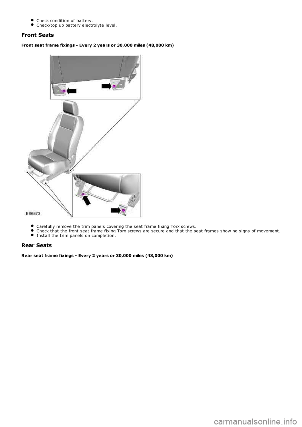
Front seat frame fixings - Every 2 years or 30,000 miles (48,000 km)
Careful ly remove t he trim panel s covering t he s eat frame fi xi ng Torx s crews .Check t hat the front s eat frame fixing Torx s crews are secure and that the seat frames s how no s i gns of movement .Ins t all the trim panel s on completi on.
Rear Seats
Rear seat frame fixings - Every 2 years or 30,000 miles (48,000 km)
Page 183 of 3229
Check condit ion of batt ery.
Check/top up bat tery electrolyte level .
Front seats
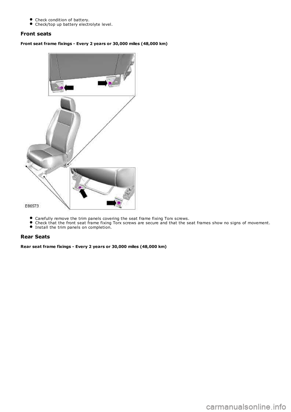
Front seat frame fixings - Every 2 years or 30,000 miles (48,000 km) Careful ly remove t he trim panel s covering t he s eat frame fi xi ng Torx s crews .
Check t hat the front s eat frame fixing Torx s crews are secure and that the seat fram
es s how no s i gns of movement .Ins t all the trim panel s on completi on.
Rear Seats
Rear seat frame fixings - Every 2 years or 30,000 miles (48,000 km)
Page 2075 of 3229
Publi s hed: 11-May-2011
Multifunction Electronic Modules - Multifunction Electronic Module
Diagnosi s and Tes ti ng
Description and Operation
For a detail ed descripti on of the mult ifuncti on electronic cont rol modules , refer to the relevant Des cri pt ion and Operati on
s ect ion i n t he works hop manual .
REFER to: Module Cont roll ed Funct ions (419-10 Mult ifunct ion Elect ronic Modules , Descripti on and Operat ion).
Inspection and Verification CAUTION: Di agnos is by s ubs ti tut ion from a donor vehicle is
NO T acceptabl e. Subs ti tut ion of cont rol modules does
not guarant ee confirmat ion of a faul t, and may als o caus e addit ional fault s i n t he v ehi cl e being t est ed and/or t he donor
vehi cl e.
1. Verify t he cus t omer concern.
1.
2. Vis ually ins pect for obvious s igns of electrical damage.
2.
Visual Inspection Electrical
Fuse(s ) Electrical connect or(s )
W iri ng Harnes s
3.
If an obvious cause for an obs erved or report ed concern is found, correct t he caus e (if pos s ible) before
proceeding t o t he next s t ep.
3.
4. If t he caus e is not vis ually evi dent , check for Di agnos ti c Trouble Codes (DTCs) and refer t o t he DTC Index.
4.
DTC Index
• NOTE: If the control modul e is sus pect and t he vehicle remains under manufact urer warranty, refer to the W arrant y Poli cy
and Procedures manual (s ect ion B1.2), or determine i f any prior approval programme i s i n operat ion, prior t o t he
ins t al lat ion of a new modul e.
• NOTE: The DTC Index in t his s ecti on s hows informati on for DTCs t hat could be logge d in the Driver Door Modul e (DDM) or
Pass enger Door Module (PDM). For diagnosi s and t est ing i nformati on for: Dri ver Seat module.
REFER to: Seats (501-10 Seati ng, Diagnos is and Tes t ing).
Informat ion and Ent ert ai nment modul e.
REFER to: Informati on and Ent ert ainment Syst em (415-01 Informati on and Ent ert ainment Syst em, Diagnos is and Tes ti ng).
• NOTE: Generic scan t ool s may not read the codes li st ed, or may read only fi ve digi t codes . Mat ch the five di git s from t he
s can tool to the firs t fi ve di git s of the seven digi t code l is ted to ident ify t he fa ul t (t he las t t wo digi ts gi ve addi ti onal
informat ion read by the manufact urer approved diagnos t ic s ys tem).
• NOTE: W hen performing el ect ri cal volt age or resi s tance tes t s, al ways us e a digit al mult imet er (DMM) accurate to three
deci mal places , and wi th an up-to-date cali brat ion cert ificate. W hen t es ti ng res is t a nce, always take t he res i st ance of t he
DMM leads int o account.
• NOTE: Check and recti fy bas ic faul ts before beginni ng diagnos t ic rout ines i nvol vi n g pinpoint t es t s.
• NOTE: Ins pect connect ors for s igns of water ingres s , and pins for damage and/or co rros ion.
• NOTE: If DTCs are recorded and, aft er performi ng the pi npoi nt tes ts , a fault is no t present , an int ermi tt ent concern may
be t he caus e. Always check for loose connect ions and corroded terminals .
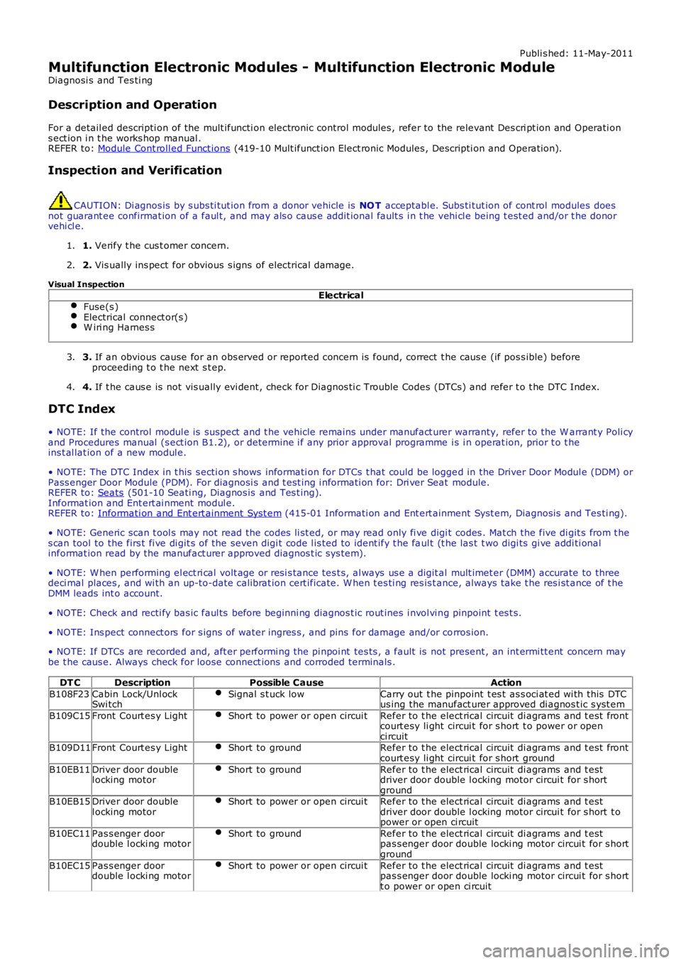
DT C Description Possible Cause Action
B108F23 Cabin Lock/Unl ock
Swi tch Signal s t uck low Carry out t he pinpoint t es t as s oci at ed wi th this DTC
us ing the manufact urer approved di agnos t ic s yst em
B109C15 Front Court es y Light Short to power or open circui t Refer to t he elect rical circuit di agrams and t est front
court esy li ght circui t for s hort t o power or open
ci rcuit
B109D11 Front Court es y Light Short to ground Refer to t he elect rical circuit di agrams and t est front
court esy li ght circui t for s hort ground
B10EB11 Driver door double
l ocking motor Short to ground Refer to t he elect rical circuit di agrams and t est
driver door double l ocking motor circui t for s hort
ground
B10EB15 Driver door double
l ocking motor Short to power or open circui t Refer to t he elect rical circuit di agrams and t est
driver door double l ocking motor circui t for s hort t o
power or open ci rcuit
B10EC11 Pas s enger door
double l ocki ng motor Short to ground Refer to t he elect rical circuit di agrams and t est
pas s enger door double locki ng motor circui t for s hort
ground
B10EC15 Pas s enger door
double l ocki ng motor Short to power or open circui t Refer to t he elect rical circuit di agrams and t est
pas s enger door double locki ng motor circui t for s hort
t o power or open ci rcuit
Page 2173 of 3229
Publi s hed: 11-May-2011
Seating - Seats
Des cript ion and Operat ion
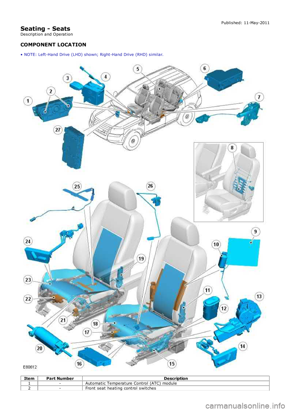
COMPONENT LOCATION
• NOTE: Left -Hand Drive (LHD) shown; Right -Hand Drive (RHD) s imi lar. Item
Part Number Description
1 -Aut omat ic Temperat ure Control (ATC) module
2 -Front seat heati ng cont rol s wit ches
Page 2174 of 3229
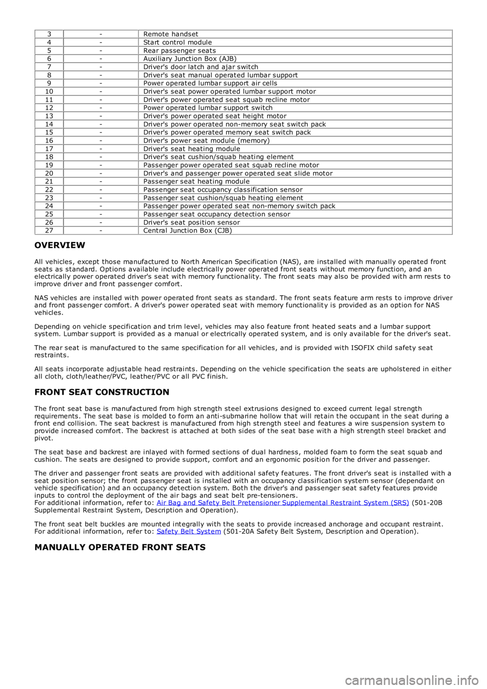
3
-Remote hands et
4 -Start control modul e
5 -Rear pas senger s eat s
6 -Auxi liary Junct ion Box (AJB)
7 -Dri ver's door lat ch and ajar s wit ch
8 -Dri ver's s eat manual operat ed lumbar s upport
9 -Power operat ed lumbar s upport air cel ls
10 -Dri ver's s eat power operat ed lumbar s upport motor
11 -Dri ver's power operated s eat s quab recline motor
12 -Power operat ed lumbar s upport swit ch
13 -Dri ver's power operated s eat height motor
14 -Dri ver's power operated non-memory s eat s wit ch pack
15 -Dri ver's power operated memory s eat s wit ch pack
16 -Dri ver's power s eat modul e (memory)
17 -Dri ver's s eat heat ing modul e
18 -Dri ver's s eat cus hion/squab heati ng element
19 -Pas s enger power operated s eat s quab recl ine motor
20 -Dri ver's and pas senger power operat ed s eat s l ide mot or
21 -Pas s enger s eat heat ing modul e
22 -Pas s enger s eat occupancy clas s ifi cat ion sens or
23 -Pas s enger s eat cus hion/s quab heati ng element
24 -Pas s enger power operated s eat non-memory s wit ch pack
25 -Pas s enger s eat occupancy detecti on s ens or
26 -Dri ver's s eat pos i ti on s ens or
27 -Cent ral Junct ion Box (CJB)
OVERVIEW
All vehicles , except thos e manufactured to Nort h American Specificati on (NAS), are i ns tall ed wit h manuall y operated front
s eat s as s t andard. Opt ions available include electricall y power operat ed front s eat s wi thout memory functi on, and an
electricall y power operat ed dri ver's s eat wit h memory funct ionalit y. The front s eats may als o be provi ded wit h arm rest s t o
improve dri ver and front pass enger comfort .
NAS vehicles are ins tal led wi th power operat ed front seat s as s tandard. The front se at s feat ure arm res ts t o i mprove driver
and front pas s enger comfort. A dri ver's power operated s eat wit h memory funct ionalit y i s provided as an opt ion for NAS
vehi cl es.
Dependi ng on vehi cl e s peci fi cat ion and t ri m l evel , vehi cl es may als o feature front h eat ed s eat s and a l umbar support
s ys t em. Lumbar s upport is provided as a manual or electrically operat ed s yst em, and i s onl y available for t he dri ver's s eat.
The rear s eat is manufact ured t o t he s ame s pecificati on for al l vehicles , and is pro vided wi th ISOFIX chi ld s afet y s eat
res t raint s .
All s eats i ncorporate adjust able head rest rai nt s . Depending on the vehicle specifica ti on the seat s are uphols t ered in eit her
all clot h, cl ot h/l eat her/PVC, l eather/PVC or all PVC finis h.
FRONT SEAT CONSTRUCTION
The front seat bas e is manufact ured from high s t rength st eel ext rus ions des igned to exceed current l egal s trengt h
requirements . The s eat bas e i s molded t o form an anti -s ubmari ne hollow that wi ll ret ain t he occupant in the s eat during a
front end col lis i on. The s eat backres t is manufact ured from high st rength s teel and features a wi re sus pens i on sys t em t o
provide i ncreased comfort . The backres t is at t ached at both si des of t he s eat bas e w it h a high st rengt h s teel bracket and
pivot.
The s eat bas e and backrest are i nl ayed wit h formed s ect ions of dual hardnes s , molded foam t o form the s eat s quab and
cus hion. The s eats are desi gned to provide s upport, comfort and an ergonomic pos it io n for t he driver and pass enger.
The dri ver and pas senger front seat s are provi ded wit h addit ional safet y feat ures . T he front driver's s eat is i nst all ed wit h a
s eat pos it ion s ens or; t he front pas s enger s eat is i ns t alled wit h an occupancy cl ass i ficati on s yst em s ens or (dependant on
vehi cl e s peci fi cat ion) and an occupancy det ect ion s ys tem. Bot h t he driver's and pas s enger seat s afet y feat ures provide
inputs to cont rol the deployment of the ai r bags and seat belt pre-t ens ioners .
For addit ional informat ion, refer t o: Air Bag and Safet y Belt Pretens ioner Supplement al Res traint Syst em (SRS) (501-20B
Suppl ement al Rest rai nt Sys tem, Des cri pti on and Operati on).
The front seat belt buckl es are mount ed i nt egrall y wi th t he s eats t o provi de increas ed anchorage and occupant res t raint .
For addit ional informat ion, refer t o: Safety Bel t Syst em (501-20A Safet y Belt Sys tem, Des cript ion and O perati on).
MANUALLY OPERATED FRONT SEATS
Page 2175 of 3229
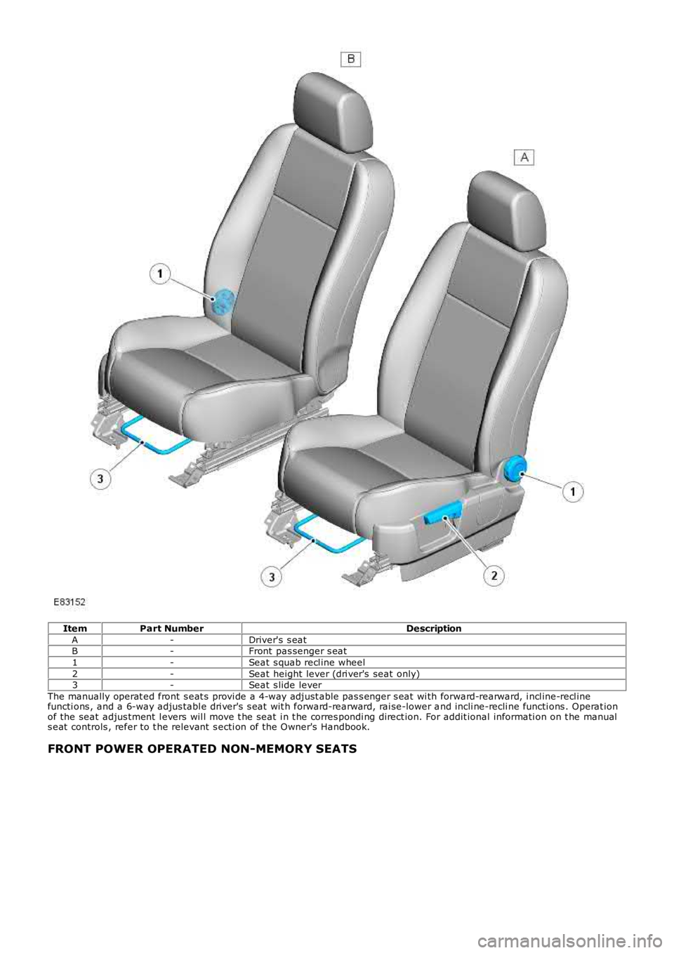
Item
Part Number Description
A -Driver's s eat
B -Front pas senger s eat
1 -Seat s quab recl ine wheel
2 -Seat height lever (dri ver's seat only)
3 -Seat s lide lever
The manually operat ed front s eat s provi de a 4-way adjust able pas s enger s eat wi th for ward-rearward, i ncl ine-recl ine
functi ons , and a 6-way adjus tabl e dri ver's s eat wit h forward-rearward, rai se-lower a nd incli ne-recli ne functi ons . Operat ion
of the seat adjus tment l evers wil l move t he seat i n t he corres pondi ng direct ion. For addit ional informati on on t he manual
s eat controls , refer to t he relevant s ecti on of the Owner's Handbook.
FRONT POWER OPERATED NON-MEMORY SEATS
Page 2181 of 3229
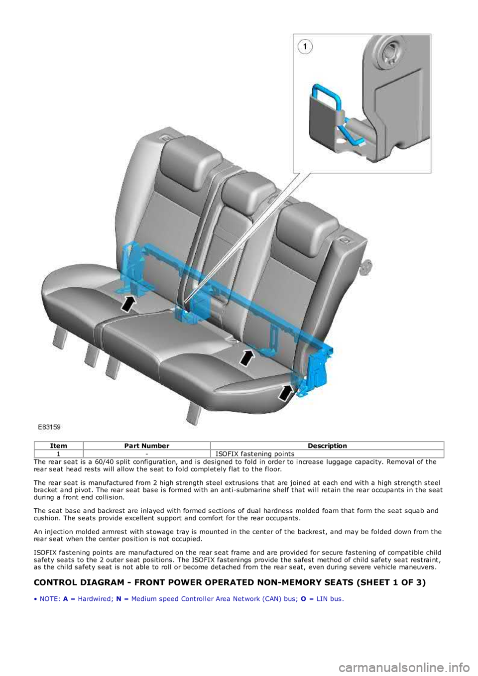
Item
Part Number Description
1 -ISOFIX fast ening point s
The rear s eat is a 60/40 s plit confi gurati on, and i s des igned to fold in order to i n crease luggage capaci ty. Removal of t he
rear s eat head res ts wi ll all ow t he s eat to fold compl et ely flat t o t he fl oor.
The rear s eat is manufact ured from 2 high s t rength st eel ext rus ions t hat are joined at each end wit h a hi gh st rengt h s teel
bracket and pi vot . The rear s eat bas e i s formed wi th an ant i-s ubmarine shelf t hat wi l l ret ai n t he rear occupants i n t he s eat
duri ng a front end col li si on.
The s eat bas e and backrest are i nl ayed wit h formed s ect ions of dual hardnes s mol ded foam that form the s eat s quab and
cus hion. The s eats provi de excell ent support and comfort for t he rear occupants .
An i nject ion molded armres t wit h s t owage tray is mount ed in the center of t he backre s t, and may be fol ded down from t he
rear s eat when the center pos it ion i s not occupi ed.
ISOFIX fast ening point s are manufact ured on the rear s eat frame and are provided for secure fas tening of compati ble chil d
s afety seat s t o the 2 outer s eat pos it ions . The ISOFIX fas t eni ngs provide t he s afes t method of chil d s afety seat res t rai nt ,
as t he chi ld s afet y s eat is not able to roll or become det ached from t he rear s eat , even during s evere vehicle maneuvers .
CONTROL DIAGRAM - FRONT POWER OPERATED NON-MEMORY SEATS (SHEET 1 OF 3)
• NOTE: A = Hardwi red; N = Medium s peed Cont roll er Area Net work (CAN) bus; O = LIN bus .
Page 2185 of 3229
6
-St art control modul e
PRINCIPLES OF OPERATION
Front Power Operated Non-Memory Seats
The dri ver's non-memory s eat wil l operate i n all i gni ti on power modes . The pas senger non-memory seat wi ll only operat e
when t he ignit ion i s i n power mode 6 (Ignit ion).
Power for front pas s enger s eat operat ion is s upplied from t he AJB via a pas s enger s e at power relay t o t he pas s enger s eat
cont rol s wit ch pack. Power for t he driver's s eat operat ion is s upplied di rectl y from the AJB t o t he dri ver's s eat cont rol
s wit ch pack. The front pas s enger and dri ver s eat power suppli es are controlled by th e CJB. The s eat s wi tch pack direct s the
volt age to t he relevant s eat adjus tment mot or when a s eat control swit ch is pres s ed. Two pins wi thin each of t he s eat
s wit ch packs cont rol t he s eat motors. Bot h pins are normal ly connect ed to ground.
The dri ver and pas senger s wit ch packs are al s o connected i n circui t wit h a bat tery-s aver t imer relay t hat i s located in, and
cont rol led by t he CJB. The bat tery-s aver t imer relay all ows operati on of the driver and pas s enger s eat cont rols for 10
mi nut es aft er the engine is s wit ched off, and the i gni ti on is then s elected t o an ap propriat e power mode. The 10 minute
t imer is res et if t he appropriat e i gni ti on power mode is retai ned and the driver's d oor i s opened or clos ed. The driver and
pass enger s eat operati on is inhibit ed i mmediat el y fol lowi ng cent ral locking of t he v ehi cl e.
Operat ing a seat mot or control swit ch appli es volt age to one of t he pins whi le t he o t her pi n remai ns connect ed t o ground.
Operat ing t he s eat motor cont rol s wit ch in the oppos it e direct ion reverses the power and ground connecti ons to the mot or,
all owing t he mot or pi ni on t o rot ate in t he oppos i te di recti on. In t he event t hat a m ot or sei zes or s t icks , an i nternal
t hermal cut -out s wit ch wil l trip to remove volt age from t he mot or.
Driver's Power Operated Memory Seat
The dri ver's memory s eat wil l operat e when t he i gni ti on is in power modes 4 (Acces so ry) and 6 (Ignit ion), and wi ll not
operate during power mode 9 (Engine crank).
Power for the driver's memory s eat operat ion i s s uppl ied di rectl y from t he AJB t o t h e power s eat module. The memory s eat
s wit ch pack i s connected t o t he power seat module that cont rol s t he operati on and me mory pos it ion of t he i ndi vi dual s eat
mot ors . The power s eat module i s connected on the medi um s peed CAN bus t o t he CJB an d the front LH and RH door
cont rol modules .
The power seat module is als o connect ed in ci rcuit wi th a batt ery-saver ti mer rel ay that is locat ed wi thin, and controlled by
t he CJB. The batt ery-saver ti mer rel ay allows operat ion of t he s eat cont rols for 10 mi nut es aft er the engine is s wi tched off,
and t he ignit ion i s t hen sel ect ed to an appropri at e power mode. The 10 minut e t imer i s res et if t he appropri at e i gni ti on
power mode is retai ned and the driver's door i s opened or clos ed. The driver's s eat operat ion is i nhi bit ed immedi ately
fol lowing cent ral locki ng of the vehicl e.
Reques t s for memory exterior mirror movements for a memory recal l are t rans mit ted on the medi um s peed CAN bus by t he
power seat module to t he front door control modul es. The front door cont rol modules direct ly control the memory s t ore and
recall pos it ions for t he memory ext eri or mirrors.
For addit ional informat ion, refer t o: Rear Vi ew Mi rrors (501-09 Rear View Mirrors , Des cript ion and Operat ion).
Power Seat Mod ule
The power seat module features driver s electable funct ions , and aut omat ic monit ori ng functi ons .
Driver Selectable Functions
Seat and ext erior mirror memory recall Immediat e s eat adjus t ment.
Seat and exterior mirror memory recall function
The memory recall functi on s ets t he driver's seat t o a s t ored pos it ion, and is acti v at ed when a swi tch pack memory
posi ti on butt on is pres sed. W hen memory recal l i s i ni ti ated, only 2 seat adjus tment mot ors wil l operat e at any one t ime to
li mit the overall current cons umpti on. To furt her minimize t he current l oad as the m otors energize, the i nit iati on of each of
t he 2 operati ng mot ors i s phas ed wi th a 10 mill is econd del ay. The cushi on s lide and backres t wil l move fi rs t , foll owed by
t he cus hion height .
As s oon as t he seat s wit ch pack memory pos it ion but ton is pres s ed, a mes sage i s t ran s mit ted by the power s eat modul e
on t he medium s peed CAN bus to the front door control modul es. The door cont rol modu les t hen act ivat e t he memory
recall pos it ions for t he exteri or mirrors. The i nst rument clus t er mess age cent er wil l di s pl ay memory recall mes s ages when
a memory recall i s acti vat ed.
The memory recall functi on operates wit h 2 s eparate modes; t he operat ion of each mod e is dependant on t he vehicle
s tat us when the seat memory posi ti on butt on is pres sed.
Memory recall operati ng modes:
One-t ouch mode Proport ional mode.
One-Touch Mode
W hen t he vehicle i s s tat ionary and a s wit ch pack memory pos it ion butt on i s pres sed, t he memory recall functi on wil l
operate in 'one-touch' mode. One t ouch mode all ows the seat and exterior mirrors t o immediatel y move t o t he request ed
s tored memory pos i ti on.
If a s eat adjus t ment or memory pos it ion but ton i s operat ed during memory recal l 'one -t ouch' mode, t he current memory
recall wi ll be cancell ed and t he seat (and ext eri or mirrors via t he medium s peed CAN bus) wi ll i mmediat el y s top movi ng.
The s eat will t hen commence movi ng in the di recti on that corresponds to the press ed s wi tch.
Page 2187 of 3229
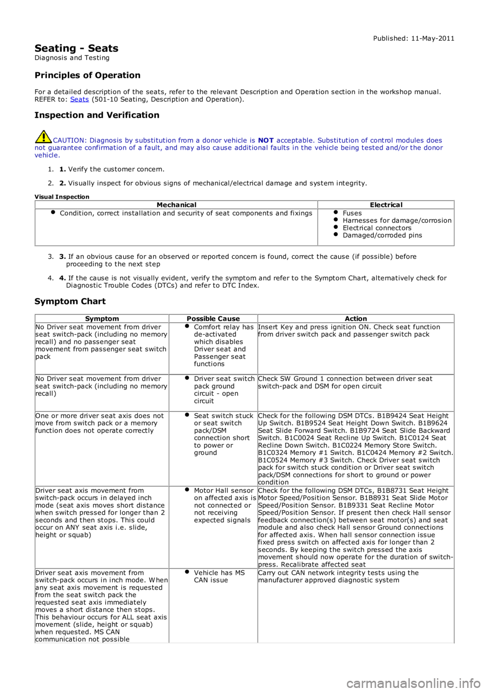
Publi s hed: 11-May-2011
Seating - Seats
Diagnosi s and Tes ti ng
Principles of Operation
For a detail ed descripti on of the seat s, refer t o the relevant Descri pti on and Opera t ion s ect ion in t he works hop manual.
REFER to: Seats (501-10 Seati ng, Des cri pti on and Operati on).
Inspection and Verification CAUTION: Di agnos is by s ubs ti tut ion from a donor vehicle is
NO T acceptabl e. Subs ti tut ion of cont rol modules does
not guarant ee confirmat ion of a faul t, and may als o caus e addit ional fault s i n t he v ehi cl e being t est ed and/or t he donor
vehi cl e.
1. Verify t he cus t omer concern.
1.
2. Vis ually ins pect for obvious s igns of mechani cal /elect rical damage and s ys t em i nt egr i ty.
2.
Visual Inspection Mechanical Electrical
Condit ion, correct ins tal lati on and s ecurit y of seat component s and fi xings Fus es
Harness es for damage/corros ion
El ect ri cal connect ors
Damaged/corroded pins
3.
If an obvious cause for an obs erved or report ed concern is found, correct t he caus e (if pos s ible) before
proceeding t o t he next s t ep
3.
4. If t he caus e is not vis ually evi dent , verify t he sympt om and refer t o t he Sympt om Ch art, al ternat ively check for
Di agnos ti c Trouble Codes (DTCs) and refer t o DTC Index.
4.
Symptom Chart Symptom Possible Cause Action
No Driver s eat movement from driver
s eat swi tch-pack (including no memory
recall ) and no pass enger seat
movement from pas s enger s eat s wi tch
pack Comfort rel ay has
de-acti vat ed
which dis ables
Dri ver s eat and
Pass enger s eat
functi ons Ins ert Key and press ignit ion ON. Check s eat funct ion
from driver swit ch pack and pas senger swi tch pack
No Driver s eat movement from driver
s eat swi tch-pack (including no memory
recall ) Dri ver s eat s wit ch
pack ground
circuit - open
circuit Check SW Ground 1 connect ion bet ween dri ver s eat
s wit ch-pack and DSM for open circuit
One or more dri ver s eat axis does not
move from s wit ch pack or a memory
funct ion does not operat e correct ly Seat s wi tch s t uck
or seat s wit ch
pack/DSM
connecti on short
to power or
ground Check for the foll owi ng DSM DTCs . B1B9424 Seat Height
Up Swit ch. B1B9524 Seat Hei ght Down Swit ch. B1B9624
Seat Sl ide Forward Swit ch. B1B9724 Seat Sl ide Backward
Swit ch. B1C0024 Seat Recli ne Up Swit ch. B1C0124 Seat
Recl ine Down Swi tch. B1C0224 Memory St ore Swi tch.
B1C0324 Memory #1 Swi tch. B1C0424 Memory #2 Swi tch.
B1C0524 Memory #3 Swi tch. Check Driver s eat s wi tch
pack for swit ch st uck condit ion or Driver seat s wit ch
pack/DSM connecti ons for s hort to ground or power
condit ion
Driver seat axis movement from
s wit ch-pack occurs i n delayed inch
mode (s eat axis moves short di s tance
when s wit ch pres s ed for l onger t han 2
s econds and t hen st ops. Thi s coul d
occur on ANY seat axis i .e. s li de,
height or s quab) Motor Hall s ens or
on affect ed axis i s
not connect ed or
not recei ving
expected si gnal s Check for the foll owi ng DSM DTCs , B1B8731 Seat Height
Motor Speed/Posi ti on Sens or. B1B8931 Seat Sl ide Mot or
Speed/Pos it ion Sens or. B1B9331 Seat Recline Motor
Speed/Pos it ion Sens or. If pres ent t hen check Hall s ens or
feedback connect ion(s ) between s eat mot or(s) and s eat
module and al so check Hall s ens or Ground connect ions
for affect ed axis . W hen hall s ens or connect ion i ss ue
fi xed pres s s wit ch on affect ed axi s for l onger t han 2
s econds. By keeping t he s wit ch pres s ed the axis
movement s hould now operate for the durati on of swi tch-
pres s. Recali brate affect ed seat
Driver seat axis movement from
s wit ch-pack occurs i n i nch mode. W hen
any s eat axi s movement i s reques ted
from the s eat s wit ch pack t he
reques ted s eat axis i mmediat el y
moves a s hort di st ance then s t ops .
This behaviour occurs for ALL seat axis
movement (s l ide, hei ght or s quab)
when reques ted. MS CAN
communicati on not pos s ible Vehi cle has MS
CAN i ss ue Carry out CAN network int egrit y t es t s us ing t he
manufacturer approved diagnost ic sys tem
Page 2189 of 3229
Publi shed: 26-Jul-2011
Seating - Heater Mats
Diagnosi s and Tes ti ng
Principles of Operation
Heated s eats incorporate heat er elements in t he cushi on and the backres t of the s eat. Each cus hion heat er el ement has at hermal sens or, whi ch suppli es a feedback temperat ure si gnal t o t he rel at ed s eat heat er modul e. The backres t heat erelement s do not have a thermal sens or, and are regulat ed at the s ame temperat ure as the cus hi on heat er elements .
For a detail ed descripti on of the seat heater mat , refer t o t he rel evant Des cript ion and Operat ion s ecti on in the workshopmanual. REFER to: Seats (501-10, Descripti on and Operat ion).
Inspection and Verification
1. Verify t he cus t omer concern.1.
2. Vis ually ins pect for obvious s igns of mechani cal or electrical damage.2.
Visual inspectionMechanicalElectrical
Seat heat er swi tches condi ti on and ins tal lati onFusesHarnes s es and connect orsSeat heat er modul eSeat heat er swi tchesSeat heat er mat
3. If an obvious cause for an obs erved or report ed concern is found, correct t he caus e (if pos s ible) beforeproceeding t o t he next s t ep.3.
4. If t he caus e is not vis ually evi dent , verify t he sympt om and refer t o t he Sympt om Chart.4.
• NOTE: If the control modul e or a component i s s us pect and the vehicle remains under manufacturer warrant y, refer t o thewarranty poli cy and procedures manual (s ect ion B1.2), or det ermine i f any prior approval programme is i n operati on, priort o the ins tall ati on of a new module/component.
• NOTE: Generic scan t ool s may not read the codes li st ed, or may read only fi ve digit codes . Mat ch the five di git s from t hes can tool to the firs t fi ve di git s of the seven digi t code l is ted to ident ify t he faul t (t he las t t wo digi ts gi ve addi ti onalinformat ion read by the manufact urer approved diagnos t ic s ys tem).
• NOTE: W hen performing el ect ri cal volt age or resi s tance tes t s, al ways us e a digit al mult imet er (DMM) accurate to threedeci mal places , and wi th an up-to-date cali brat ion cert ificate. W hen t es ti ng res is t ance, always take t he res i st ance of t heDMM leads int o account.
• NOTE: Check and recti fy bas ic faul ts before beginni ng diagnos t ic rout ines i nvol vi ng pinpoint t es t s.
• NOTE: Ins pect connect ors for s igns of water ingres s , and pins for damage and/or corros ion.
• NOTE: If DTCs are recorded and, aft er performi ng the pi npoi nt tes ts , a fault is not present , an int ermi tt ent concern maybe t he caus e. Always check for loose connect ions and corroded terminals .
DTC Index
For a compl ete lis t of all di agnos ti c troubl e codes that coul d be l ogged on t his vehicle, pleas e refer to s ect ion 100-00.
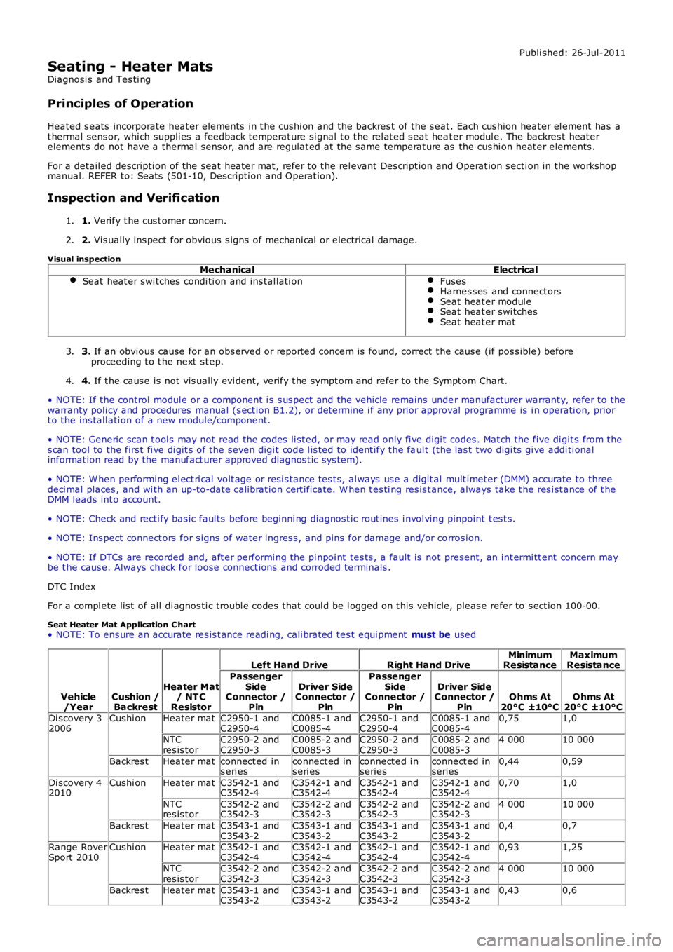
Seat Heater Mat Application C hart• NOTE: To ens ure an accurate res is t ance readi ng, cali brated tes t equi pment must be used
Vehicle/YearCushion /Backrest
Heater Mat/ NT CResistor
Left Hand DriveRight Hand DriveMinimumResistanceMaximumResistance
PassengerSideConnector /Pin
Driver SideConnector /Pin
PassengerSideConnector /Pin
Driver SideConnector /PinOhms At20°C ±10°COhms At20°C ±10°CDi scovery 32006Cushi onHeater matC2950-1 andC2950-4C0085-1 andC0085-4C2950-1 andC2950-4C0085-1 andC0085-40,751,0
NTCres is t orC2950-2 andC2950-3C0085-2 andC0085-3C2950-2 andC2950-3C0085-2 andC0085-34 00010 000
Backres tHeater matconnect ed ins eri esconnect ed ins eri esconnect ed i nseriesconnect ed inseries0,440,59
Di scovery 42010Cushi onHeater matC3542-1 andC3542-4C3542-1 andC3542-4C3542-1 andC3542-4C3542-1 andC3542-40,701,0
NTCres is t orC3542-2 andC3542-3C3542-2 andC3542-3C3542-2 andC3542-3C3542-2 andC3542-34 00010 000
Backres tHeater matC3543-1 andC3543-2C3543-1 andC3543-2C3543-1 andC3543-2C3543-1 andC3543-20,40,7
Range RoverSport 2010Cushi onHeater matC3542-1 andC3542-4C3542-1 andC3542-4C3542-1 andC3542-4C3542-1 andC3542-40,931,25
NTCres is t orC3542-2 andC3542-3C3542-2 andC3542-3C3542-2 andC3542-3C3542-2 andC3542-34 00010 000
Backres tHeater matC3543-1 andC3543-2C3543-1 andC3543-2C3543-1 andC3543-2C3543-1 andC3543-20,430,6