glove box LAND ROVER FRELANDER 2 2006 Repair Manual
[x] Cancel search | Manufacturer: LAND ROVER, Model Year: 2006, Model line: FRELANDER 2, Model: LAND ROVER FRELANDER 2 2006Pages: 3229, PDF Size: 78.5 MB
Page 1830 of 3229
• NOTE: The fus i bl e l inks are mount ed on t he inboard s i de of the BJB behind a series of removable covers .
The CJB is mount ed behind t he glovebox and recei ves it s main power s uppl y from the BJB. In addi ti on to cont aining bl adefus es , the CJB i s t he main controll er for a number of vehicle s ys t ems. Thes e functi ons are out li ned in t he rel evant s ect ionsof thi s manual .
The AJB is locat ed beneat h t he luggage compartment carpet , adjacent t he spare wheel wel l. The AJB i s a modular des ign,and compris es up t o 3 individual elements depending on vehicle specificati on. The AJB cont ains bl ade and J-cas e fuses ,and rel ays to di st ribute el ect ri cal power to sys t ems used at the rear of t he vehi cle. The AJB receives it s mai n power s upplyfrom the BJB.
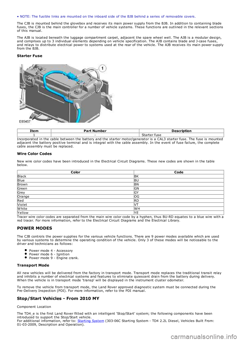
Starter Fuse
ItemPart NumberDescription
1-Starter fus e
Incorporat ed i n the cable bet ween t he bat t ery and t he s tarter mot or/generat or is a CAL3 st art er fus e. The fus e is mount edadjacent t he batt ery pos it ive t erminal and is i ntegral wi th t he cable as s embly. In the event of fus e fai lure, t he completecabl e as sembl y mus t be repl aced.
Wire Color Codes
New wi re col or codes have been i ntroduced i n the El ect ri cal Ci rcuit Di agrams . Thes e new codes are s hown i n t he tablebelow.
ColorCode
BlackBK
BlueBUBrownBN
GreenGN
GreyGYOrangeOG
RedRD
Viol etVTW hi teW H
Y ell owY E
Tracer wire col or codes are s eparat ed from the main wi re col or code by a hyphen, t hus BU-RD equat es to a blue wire wit h ared tracer. For more informat ion, refer to t he Elect rical Circui t Diagrams and the El ect ri cal Library.
POWER MODES
The CJB cont rol s the power s uppl ies for the vari ous vehi cl e functi ons. There are 9 power modes availabl e which are usedby vari ous s ys tems to det ermi ne t he operati ng condit ion of t he vehi cle. Only 3 of thes e modes wil l be noti ceable t o t hedri ver and t echnici ans as foll ows:
Power mode 4 - Acces s oryPower mode 6 - Igni ti onPower mode 9 - Engine crank.
Transport Mode
All new vehicles will be del ivered from the factory in t rans port mode. Trans port mode repl aces t he t radit ional trans i t relayand inhibi ts a number of el ect ri cal s ys t ems and feat ures t o eli mi nat e quies cent drain from the bat tery during del ivery.W hen t he vehicle i s in transport mode 't rans p' wi ll be di spl ayed i n t he ins trument cl ust er odomet er.
To remove the vehicle from t rans port mode, the Land Rover approved di agnos ti c s ys t em mus t be connect ed during t hePre-Delivery Ins pect ion (PDI). For more i nformati on, refer t o the PDI manual .
Stop/Start Vehicles - From 2010 MY
Component Locat ion
The TD4_e is t he first Land Rover fit t ed wit h an i ntell igent ‘St op/Start’ s yst em; t he fol lowing component s have beenint roduced to support t he Stop/St art vehicle.For addit ional informat ion, refer t o: Starti ng Sys t em (303-06C Starti ng Syst em - TD4 2.2L Di es el, Vehicles Bui lt From:01-03-2009, Descripti on and Operat ion).
Page 1918 of 3229
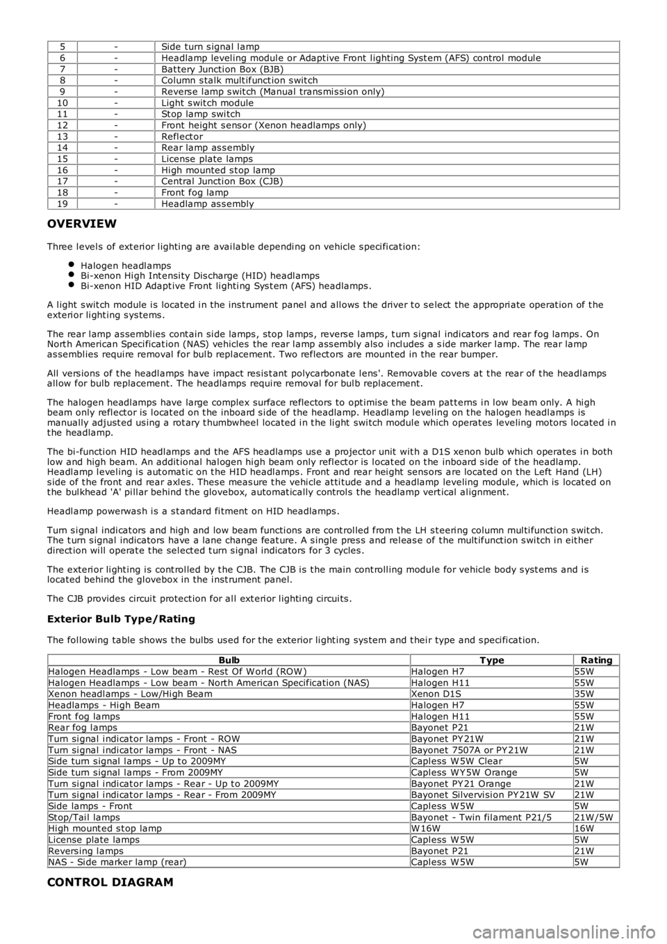
5-Side turn s ignal l amp
6-Headlamp level ing modul e or Adapt ive Front l ighti ng Sys t em (AFS) control modul e
7-Bat tery Juncti on Box (BJB)8-Column s talk mult ifunct ion s wit ch
9-Revers e l amp s wit ch (Manual trans mi s si on only)
10-Light s wit ch module11-St op lamp swi tch
12-Front height s ens or (Xenon headlamps only)
13-Refl ect or14-Rear lamp as s embly
15-License plate lamps
16-Hi gh mounted s t op lamp17-Central Juncti on Box (CJB)
18-Front fog lamp
19-Headlamp as s embly
OVERVIEW
Three l evel s of ext eri or l ighti ng are avai lable dependi ng on vehicle s peci fi cat ion:
Halogen headl ampsBi-xenon Hi gh Int ensi ty Dis charge (HID) headl ampsBi-xenon HID Adapt ive Front li ghti ng Sys t em (AFS) headlamps .
A l ight s wit ch module i s located i n t he ins t rument panel and all ows t he driver t o s elect the appropri ate operat ion of t heexteri or li ght ing s ys tems .
The rear l amp as sembl ies cont ain si de lamps , s top lamps , revers e l amps , t urn s i gnal indi cat ors and rear fog lamps . OnNort h American Speci ficat ion (NAS) vehicles the rear l amp as s embly als o incl udes a side marker l amp. The rear lampas sembl ies requi re removal for bul b repl acement. Two reflect ors are mount ed in the rear bumper.
All vers ions of t he headl amps have impact res is t ant polycarbonat e l ens '. Removable covers at t he rear of t he headl ampsall ow for bulb replacement. The headlamps requi re removal for bul b repl acement.
The halogen headl amps have large complex surface reflectors to opt imis e t he beam patt erns i n l ow beam only. A hi ghbeam only refl ect or is l ocat ed on t he inboard s i de of the headlamp. Headl amp l evel ing on t he halogen headl amps ismanually adjust ed us ing a rot ary t humbwheel located i n t he li ght swi tch modul e which operat es leveling motors located i nt he headlamp.
The bi-functi on HID headl amps and the AFS headlamps us e a projector unit wit h a D1S xenon bulb whi ch operates i n bothlow and high beam. An addit ional hal ogen hi gh beam only refl ect or is l ocat ed on t he inboard s ide of t he headlamp.Headl amp l evel ing i s aut omat ic on t he HID headl amps . Front and rear hei ght sens ors are located on the Left Hand (LH)s ide of t he front and rear axl es. Thes e meas ure t he vehi cle at ti tude and a headlamp leveling modul e, which is locat ed ont he bul khead 'A' pi ll ar behind t he glovebox, aut omat icall y cont rol s t he headlamp vert ical al ignment.
Headl amp powerwas h i s a s t andard fi tment on HID headlamps .
Turn s i gnal indi cat ors and high and low beam functi ons are cont rol led from t he LH s teeri ng column mul ti functi on s wit ch.The t urn s ignal indicators have a lane change feat ure. A s ingle pres s and rel eas e of t he mult ifunct ion s wi tch i n eit herdirect ion wi ll operat e t he sel ect ed t urn s ignal indicators for 3 cycles .
The exteri or li ght ing i s cont rol led by t he CJB. The CJB i s t he main cont roll ing modul e for vehicle body s yst ems and i slocated behind the gl ovebox in the i nst rument panel.
The CJB provides circui t protect ion for al l ext eri or l ighti ng circui ts .
Exterior Bulb Typ e/Rating
The fol lowing table shows t he bulbs us ed for t he exterior li ght ing sys tem and t hei r type and s peci fi cat ion.
BulbT ypeRating
Halogen Headlamps - Low beam - Rest O f W orl d (ROW )Halogen H755W
Halogen Headlamps - Low beam - Nort h American Specificati on (NAS)Halogen H1155WXenon headl amps - Low/Hi gh BeamXenon D1S35W
Headlamps - Hi gh BeamHalogen H755W
Front fog lampsHalogen H1155WRear fog l ampsBayonet P2121W
Turn si gnal i ndi cat or lamps - Front - ROWBayonet PY 21W21W
Turn si gnal i ndi cat or lamps - Front - NASBayonet 7507A or PY 21W21WSide turn s ignal l amps - Up t o 2009MYCapl ess W 5W Clear5W
Side turn s ignal l amps - From 2009MYCapl ess W Y 5W Orange5W
Turn si gnal i ndi cat or lamps - Rear - Up t o 2009MYBayonet PY 21 Orange21WTurn si gnal i ndi cat or lamps - Rear - From 2009MYBayonet Silvervi si on PY 21W SV21W
Side lamps - FrontCapl ess W 5W5W
St op/Tai l lampsBayonet - Twin fil ament P21/521W /5WHi gh mount ed s t op lampW 16W16W
License plate lampsCapl ess W 5W5W
Revers ing l ampsBayonet P2121WNAS - Si de marker lamp (rear)Capl ess W 5W5W
CONTROL DIAGRAM
Page 1953 of 3229
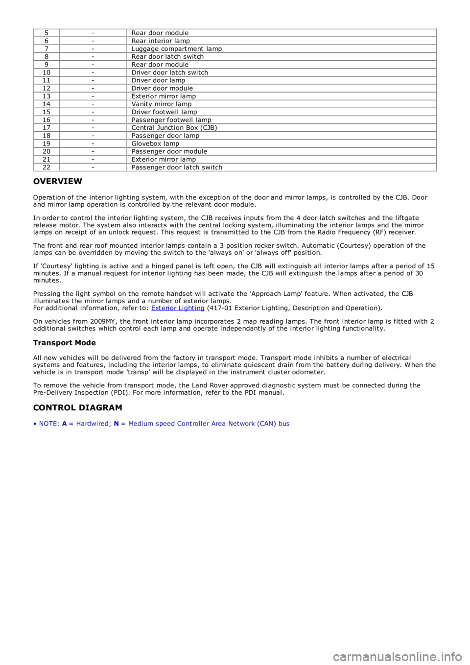
5-Rear door module
6-Rear i nterior lamp
7-Luggage compart ment lamp8-Rear door lat ch swit ch
9-Rear door module
10-Dri ver door lat ch swi tch11-Dri ver door lamp
12-Dri ver door module
13-Ext eri or mirror lamp14-Vani ty mirror l amp
15-Dri ver foot well l amp
16-Pas s enger foot well l amp17-Cent ral Junct ion Box (CJB)
18-Pas s enger door lamp
19-Glovebox lamp20-Pas s enger door module
21-Ext eri or mirror lamp
22-Pas s enger door lat ch swi tch
OVERVIEW
Operat ion of t he int erior l ighti ng s ys t em, wit h t he excepti on of the door and mi rror lamps , is controlled by the CJB. Doorand mi rror l amp operat ion i s cont rol led by t he rel evant door modul e.
In order to cont rol t he int erior l ighti ng s ys t em, the CJB recei ves i nput s from the 4 door l atch s wit ches and the l iftgat erel eas e motor. The s ys tem als o i nt eracts wit h t he cent ral locking s ys tem, i lluminating the interior lamps and the mirrorlamps on receipt of an unlock request . This reques t is trans mi tt ed t o t he CJB from the Radio Frequency (RF) receiver.
The front and rear roof mounted interior lamps contai n a 3 pos i ti on rocker s wi tch. Aut omati c (Courtes y) operati on of thelamps can be overridden by movi ng the s wi tch t o t he 'al ways on' or 'always off' positi on.
If 'Court es y' li ght ing i s acti ve and a hinged panel i s left open, t he CJB wil l ext inguis h all i nterior lamps after a period of 15mi nut es. If a manual request for int erior l ighti ng has been made, t he CJB wi ll exti nguis h the l amps aft er a peri od of 30mi nut es.
Pres s ing t he li ght symbol on t he remot e hands et wi ll act ivat e t he 'Approach Lamp' feat ure. W hen act ivated, t he CJBil lumi nat es t he mirror l amps and a number of ext eri or l amps.For addit ional informat ion, refer t o: Ext eri or Li ght ing (417-01 Ext erior Light ing, Descri pti on and Operat ion).
On vehicles from 2009MY , t he front int erior l amp incorporat es 2 map reading l amps. The front i nt eri or lamp i s fit ted wi th 2addi ti onal s wi tches which cont rol each lamp and operate i ndependant ly of t he i nt eri or light ing funct ionalit y.
Transport Mode
All new vehicles will be del ivered from the factory in t rans port mode. Trans port mode i nhi bit s a number of el ect ri cals ys t ems and feat ures , including t he i nt eri or lamps , to el imi nate qui es cent drain from t he bat t ery duri ng delivery. W hen thevehi cl e i s in trans port mode 't ransp' wi ll be dis played i n the ins trument cl us t er odomet er.
To remove the vehicle from t rans port mode, the Land Rover approved di agnos ti c s ys t em mus t be connect ed during t hePre-Delivery Ins pect ion (PDI). For more i nformati on, refer t o the PDI manual .
CONTROL DIAGRAM
• NOTE: A = Hardwi red; N = Medium s peed Cont roll er Area Net work (CAN) bus
Page 1955 of 3229
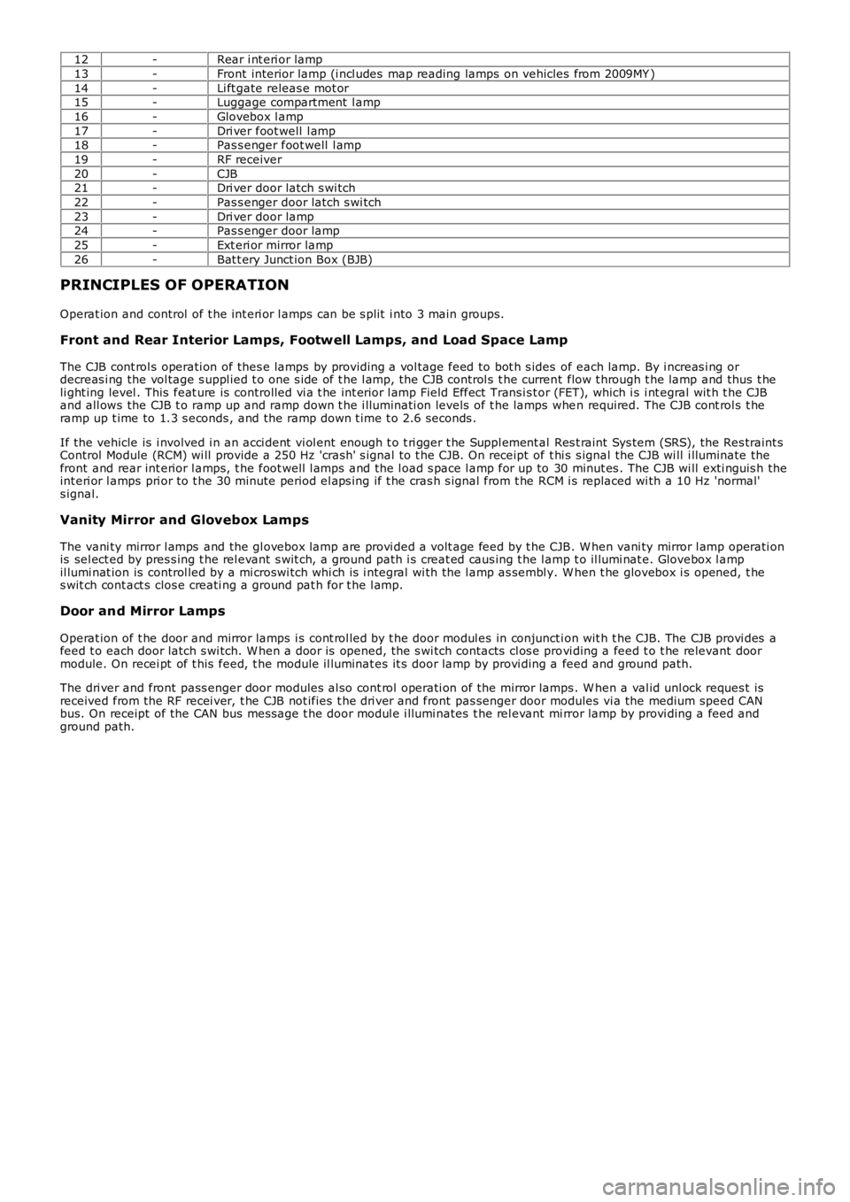
12-Rear i nt eri or lamp
13-Front interior lamp (i ncl udes map reading lamps on vehicles from 2009MY )
14-Li ft gate releas e mot or15-Luggage compartment l amp
16-Glovebox l amp
17-Dri ver foot well l amp18-Pas s enger foot well l amp
19-RF receiver
20-CJB21-Dri ver door latch s wi tch
22-Pas s enger door latch s wi tch
23-Dri ver door lamp24-Pas s enger door lamp
25-Ext eri or mirror lamp
26-Bat t ery Junct ion Box (BJB)
PRINCIPLES OF OPERATION
Operat ion and control of t he int eri or l amps can be s plit i nto 3 main groups.
Front and Rear Interior Lamps, Footwell Lamps, and Load Space Lamp
The CJB cont rol s operati on of thes e lamps by providing a vol tage feed to bot h s ides of each lamp. By i ncreas i ng ordecreas i ng the vol tage s uppl ied t o one s ide of t he l amp, the CJB control s t he current flow t hrough t he lamp and thus t heli ght ing level . This feat ure is controlled vi a t he int erior l amp Field Effect Trans is t or (FET), which i s i nt egral wit h t he CJBand all ows the CJB t o ramp up and ramp down t he i lluminati on levels of t he lamps when required. The CJB cont rol s t heramp up t ime to 1.3 s econds , and the ramp down t ime t o 2.6 seconds .
If the vehicle is i nvolved i n an acci dent vi ol ent enough t o t ri gger t he Suppl ement al Res t raint Sys tem (SRS), the Res traint sControl Module (RCM) wi ll provide a 250 Hz 'crash' s ignal to t he CJB. On receipt of t hi s s ignal the CJB wi ll i lluminate thefront and rear int erior l amps, t he foot well l amps and the l oad s pace l amp for up to 30 minut es . The CJB wi ll exti nguis h theint eri or l amps pri or to t he 30 minute period el aps ing if t he cras h s ignal from t he RCM i s replaced wi th a 10 Hz 'normal's ignal.
Vanity Mirror and Glovebox Lamps
The vani ty mirror l amps and the gl ovebox lamp are provi ded a volt age feed by t he CJB. W hen vani ty mirror l amp operati onis sel ect ed by pres s ing t he rel evant s wit ch, a ground path i s creat ed caus ing t he l amp t o il lumi nat e. Glovebox l ampil lumi nat ion is control led by a mi croswi tch whi ch is i ntegral wi th the l amp as sembl y. W hen t he glovebox i s opened, t hes wit ch cont act s clos e creati ng a ground pat h for t he l amp.
Door and Mirror Lamps
Operat ion of t he door and mirror lamps i s cont rol led by t he door modul es in conjuncti on wit h t he CJB. The CJB provi des afeed t o each door latch s wi tch. W hen a door is opened, the s wi tch contacts cl os e provi ding a feed t o t he relevant doormodule. On recei pt of t his feed, t he module il luminat es it s door lamp by provi ding a feed and ground path.
The dri ver and front pass enger door modules al so cont rol operati on of the mirror lamps . W hen a val id unl ock reques t isreceived from the RF recei ver, t he CJB not ifies t he dri ver and front pas senger door modules vi a the medium speed CANbus. On receipt of the CAN bus mes sage t he door modul e i llumi nates t he rel evant mi rror lamp by provi ding a feed andground path.
Page 1970 of 3229
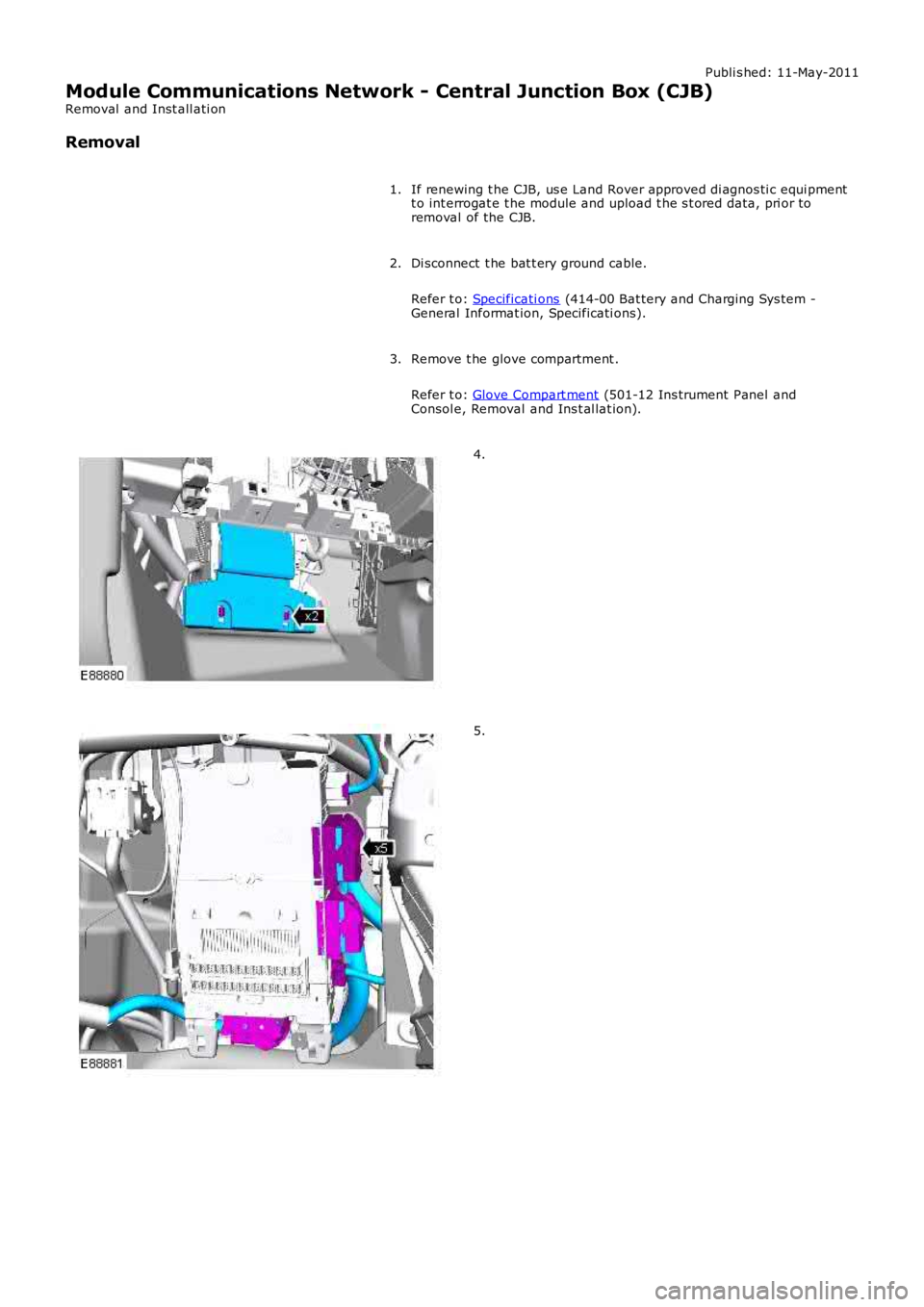
Publi s hed: 11-May-2011
Module Communications Network - Central Junction Box (CJB)
Removal and Inst all ati on
Removal
If renewing t he CJB, us e Land Rover approved di agnos ti c equi pmentt o int errogat e t he module and upload t he s t ored data, pri or toremoval of the CJB.
1.
Di sconnect t he bat t ery ground cable.
Refer t o: Specificati ons (414-00 Bat tery and Charging Sys tem -General Informat ion, Specificati ons).
2.
Remove t he glove compartment .
Refer t o: Glove Compart ment (501-12 Ins trument Panel andConsol e, Removal and Ins t al lat ion).
3.
4.
5.
Page 1972 of 3229
Publi s hed: 11-May-2011
Module Communications Network - Battery Junction Box (BJB)TD4 2.2L
Diesel
Removal and Inst all ati on
Removal
Remove t he bumper armature.
Refer t o: Front Bumper (501-19 Bumpers , Removal and Ins tall ati on).
1.
Remove t he air cleaner hous ing.
Refer t o: Air Cleaner (303-12A Intake Ai r Dis tribut ion and Fil tering -I6 3.2L Pet rol, Removal and Ins t al lat ion).
2.
Remove t he s econdary bulkhead cent er panel.
Refer t o: Secondary Bulkhead Cent er Panel - TD4 2.2L Dies el(501-02 Front End Body Panel s, Removal and Ins tal lati on).
3.
Remove t he brake boost er.
Refer t o: Brake Boost er (206-07 Power Brake Act uat ion, Removaland Inst all at ion).
4.
Remove t he ABS module.
Refer t o: Ant i-Lock Brake Sys t em (ABS) Modul e (206-09A Anti -LockControl, Removal and Ins tall ati on).
5.
Remove t he fuel fi red boos ter heater.
Refer t o: Fuel Fired Boos t er Heat er (412-02B Auxil iary Cli mateControl, Removal and Ins tall ati on).
6.
Remove both headlamps .
Refer t o: Headl amp As sembl y (417-01 Ext eri or Li ght ing, Removaland Inst all at ion).
7.
Remove t he engi ne upper s upport ins ulat or.
Refer t o: Engi ne Upper Support Ins ulat or (303-01A Engine - I6 3.2LPetrol, Removal and Ins tall ati on).
8.
Remove t he glove compartment l id.
Refer t o: Glove Compart ment (501-12 Ins trument Panel andConsol e, Removal and Ins t al lat ion).
9.
Page 1992 of 3229
Publi s hed: 11-May-2011
Module Communications Network - Battery Junction Box (BJB)I6 3.2L
Petrol
Removal and Inst all ati on
Removal
Remove t he bumper armature.
Refer t o: Front Bumper (501-19 Bumpers , Removal and Ins tall ati on).
1.
Remove t he air cleaner hous ing.
Refer t o: Air Cleaner (303-12A Intake Ai r Dis tribut ion and Fil tering -I6 3.2L Pet rol, Removal and Ins t al lat ion).
2.
Remove t he s econdary bulkhead cent er panel.
Refer t o: Secondary Bulkhead Cent er Panel - I6 3.2L Pet rol (501-02Front End Body Panel s, Removal and Ins t al lat ion).
3.
Remove t he brake boost er.
Refer t o: Brake Boost er (206-07 Power Brake Act uat ion, Removaland Inst all at ion).
4.
Remove t he ABS module.
Refer t o: Ant i-Lock Brake Sys t em (ABS) Modul e (206-09A Anti -LockControl, Removal and Ins tall ati on).
5.
Remove both headlamps .
Refer t o: Headl amp As sembl y (417-01 Ext eri or Li ght ing, Removaland Inst all at ion).
6.
Remove t he engi ne upper s upport ins ulat or.
Refer t o: Engi ne Upper Support Ins ulat or (303-01A Engine - I6 3.2LPetrol, Removal and Ins tall ati on).
7.
Remove t he glove compartment l id.
Refer t o: Glove Compart ment (501-12 Ins trument Panel andConsol e, Removal and Ins t al lat ion).
8.
Page 2072 of 3229
3-Touch Screen Dis play (TAD)
4-Integrat ed Head Unit (IHU) - Hi-Li ne
5-Bl uet ooth phone module6-Ampl ifier/t uner
7-Di git al Audio Broadcas t (DAB) recei ver
8-Navigat ion computer
OVERVIEW
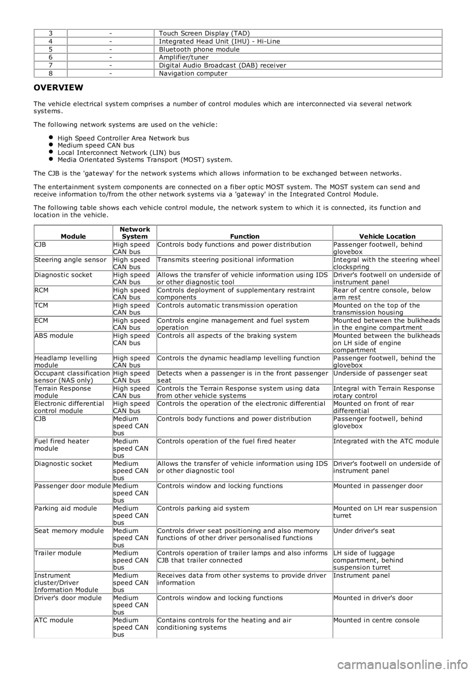
The vehi cl e elect rical s ys t em compri s es a number of control modul es which are int erconnected vi a s everal net works ys t ems .
The fol lowing net work sys tems are us ed on t he vehi cle:
High Speed Controll er Area Network busMedium speed CAN busLocal Int erconnect Network (LIN) busMedia O rient ated Sys tems Transport (MOST) s yst em.
The CJB is the 'gat eway' for the net work s yst ems whi ch allows informati on to be exchanged bet ween networks .
The entertainment s yst em components are connected on a fi ber opt ic MO ST sys t em. The MOST s ys t em can s end andreceive i nformat ion to/from t he other network s ys t ems via a 'gat eway' in the Integrat ed Control Modul e.
The fol lowing table shows each vehi cle control modul e, t he network s yst em to whi ch it i s connected, it s funct ion andlocati on in the vehicle.
ModuleNetw orkSystemFunctionVehicle Location
CJBHigh s peedCAN busControl s body functi ons and power dis t ri but ionPass enger footwell , behi ndgloveboxSt eering angle sens orHigh s peedCAN busTrans mit s s t eering pos it ional informati onInt egral wit h t he s teeri ng wheelclocks pri ngDi agnos ti c s ocketHigh s peedCAN busAll ows the trans fer of vehicle informati on usi ng IDSor other diagnos t ic t oolDri ver's footwel l on unders i de ofins trument panel
RCMHigh s peedCAN busControl s deployment of s upplementary res t raintcomponentsRear of centre cons ole, belowarm res t
TCMHigh s peedCAN busControl s automat ic t rans mi ss i on operati onMount ed on t he t op of thetransmis s ion housi ng
ECMHigh s peedCAN busControl s engine management and fuel sys t emoperati onMount ed between the bulkheadsin the engine compart ment
ABS moduleHigh s peedCAN busControl s all as pect s of the braking s yst emMount ed between the bulkheadson LH s ide of enginecompartment
Headlamp l evel li ngmoduleHigh s peedCAN busControl s t he dynami c headl amp l evell ing funct ionPass enger footwell , behi nd t heglovebox
Occupant clas si fi cat ions ensor (NAS only)High s peedCAN busDetects when a pas senger is i n t he front pas s engers eatUnders ide of pass enger seat
Terrain Res pons emoduleHigh s peedCAN busControl s t he Terrai n Res pons e s yst em us i ng dat afrom ot her vehicl e s ys t emsInt egral wit h Terrain Res pons erot ary controlElectronic different ialcont rol moduleHigh s peedCAN busControl s t he operati on of the el ect ronic di fferenti alMount ed on front of reardifferent ialCJBMedi umspeed CANbus
Control s body functi ons and power dis t ri but ionPass enger footwell , behi ndglovebox
Fuel fired heatermoduleMedi umspeed CANbus
Control s operat ion of t he fuel fi red heaterInt egrated wit h t he ATC module
Di agnos ti c s ocketMedi umspeed CANbus
All ows the trans fer of vehicle informati on usi ng IDSor other diagnos t ic t oolDri ver's footwel l on unders i de ofins trument panel
Pas senger door moduleMedi umspeed CANbus
Control s wi ndow and locki ng functi onsMount ed i n pass enger door
Parking ai d moduleMedi umspeed CANbus
Control s parking ai d s yst emMount ed on LH rear s us pensi onturret
Seat memory modul eMedi umspeed CANbus
Control s dri ver s eat posi ti oni ng and als o memoryfuncti ons of ot her driver pers onal is ed funct ionsUnder driver's s eat
Trai ler moduleMedi umspeed CANbus
Control s operat ion of t rail er lamps and als o i nformsCJB that t rai ler connect edLH s ide of l uggagecompartment , behi nds us pensi on t urret
Inst rumentclus ter/DriverInformat ion Modul e
Medi umspeed CANbus
Recei ves dat a from ot her sys t ems to provide driverinformat ionIns t rument panel
Driver's door moduleMedi umspeed CANbus
Control s wi ndow and locki ng functi onsMount ed i n dri ver's door
ATC moduleMedi umspeed CANbus
Contains controls for the heat ing and aircondi ti oni ng s ys t emsMount ed i n cent re cons ole
Page 2073 of 3229
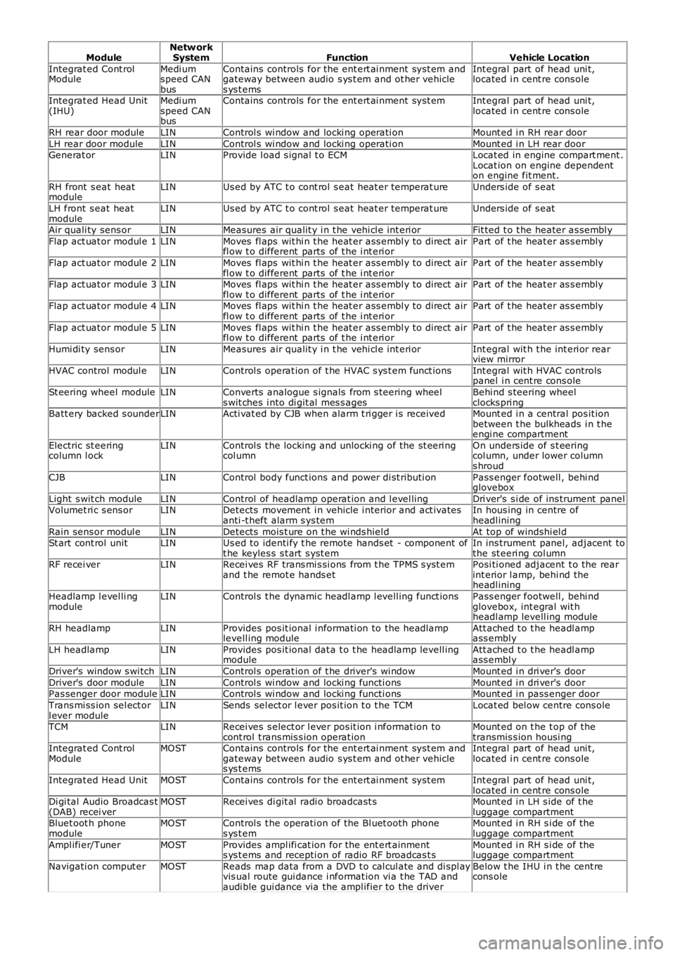
ModuleNetw orkSystemFunctionVehicle Location
Integrat ed Cont rolModuleMedi umspeed CANbus
Contains controls for the ent ert ai nment sys t em andgateway between audio s ys t em and ot her vehicles ys t ems
Int egral part of head uni t,located i n cent re cons ole
Integrat ed Head Unit(IHU)Medi umspeed CANbus
Contains controls for the ent ert ai nment sys t emInt egral part of head uni t,located i n cent re cons ole
RH rear door moduleLINControl s wi ndow and locki ng operati onMount ed i n RH rear door
LH rear door moduleLINControl s wi ndow and locki ng operati onMount ed i n LH rear doorGenerat orLINProvide l oad s ignal t o ECMLocat ed in engine compart ment .Locat ion on engine dependenton engine fit ment.
RH front s eat heatmoduleLINUs ed by ATC t o cont rol s eat heat er temperat ureUnders ide of s eat
LH front s eat heatmoduleLINUs ed by ATC t o cont rol s eat heat er temperat ureUnders ide of s eat
Air quali ty sens orLINMeasures air qualit y i n t he vehi cl e int eri orFit ted t o t he heater as sembl y
Flap act uat or modul e 1LINMoves fl aps wit hi n t he heat er ass embl y to direct airfl ow t o different parts of t he i nt eri orPart of t he heat er as s embly
Flap act uat or modul e 2LINMoves fl aps wit hi n t he heat er ass embl y to direct airfl ow t o different parts of t he i nt eri orPart of t he heat er as s embly
Flap act uat or modul e 3LINMoves fl aps wit hi n t he heat er ass embl y to direct airfl ow t o different parts of t he i nt eri orPart of t he heat er as s embly
Flap act uat or modul e 4LINMoves fl aps wit hi n t he heat er ass embl y to direct airfl ow t o different parts of t he i nt eri orPart of t he heat er as s embly
Flap act uat or modul e 5LINMoves fl aps wit hi n t he heat er ass embl y to direct airfl ow t o different parts of t he i nt eri orPart of t he heat er as s embly
Humi di ty sens orLINMeasures air qualit y i n t he vehi cl e int eri orInt egral wit h t he int eri or rearview mirror
HVAC control modul eLINControl s operat ion of t he HVAC s ys t em funct ionsInt egral wit h HVAC controlspanel i n cent re cons ole
St eering wheel moduleLINConverts analogue s ignals from s teering wheels wit ches i nto di git al mes s agesBehi nd s teering wheelclocks pri ngBatt ery backed s ounderLINActi vat ed by CJB when alarm t ri gger i s receivedMount ed i n a central pos it ionbetween t he bulkheads i n t heengi ne compartment
Electric st eeringcolumn l ockLINControl s t he locking and unlocki ng of the st eeri ngcol umnOn unders ide of s t eeringcol umn, under lower columns hroud
CJBLINControl body funct ions and power di st ributi onPass enger footwell , behi ndglovebox
Light s wit ch moduleLINControl of headlamp operat ion and l evel lingDri ver's s i de of ins trument panelVolumet ri c s ens orLINDetects movement i n vehicle i nterior and act ivatesanti -t heft alarm s ys temIn hous ing in centre ofheadl ining
Rain sens or modul eLINDetects mois t ure on t he wi nds hiel dAt top of windshi el dSt art cont rol unitLINUs ed to identi fy t he remote hands et - component oft he keyles s s t art s yst emIn ins trument panel, adjacent tothe st eeri ng col umnRF recei verLINRecei ves RF trans mi s si ons from t he TPMS s yst emand t he remot e hands etPosi ti oned adjacent t o the rearint erior l amp, behi nd theheadl ining
Headlamp l evel li ngmoduleLINControl s t he dynami c headl amp l evell ing funct ionsPass enger footwell , behi ndglovebox, int egral wit hheadl amp levell ing module
RH headlampLINProvides pos it ional i nformati on to the headlamplevell ing moduleAtt ached t o t he headl ampass embl y
LH headlampLINProvides pos it ional dat a t o t he headlamp levell ingmoduleAtt ached t o t he headl ampass embl y
Driver's window s wi tchLINControl s operat ion of t he driver's wi ndowMount ed i n dri ver's door
Driver's door moduleLINControl s wi ndow and locki ng functi onsMount ed i n dri ver's doorPas senger door moduleLINControl s wi ndow and locki ng functi onsMount ed i n pass enger door
Trans mi ss ion sel ect orl ever moduleLINSends sel ect or l ever pos it ion t o t he TCMLocat ed bel ow centre cons ole
TCMLINRecei ves s elect or l ever pos it ion i nformat ion tocont rol t rans mis s ion operat ionMount ed on t he t op of thetransmis s ion housi ngIntegrat ed Cont rolModuleMOSTContains controls for the ent ert ai nment sys t em andgateway between audio s ys t em and ot her vehicles ys t ems
Int egral part of head uni t,located i n cent re cons ole
Integrat ed Head UnitMOSTContains controls for the ent ert ai nment sys t emInt egral part of head uni t,located i n cent re cons oleDi gi tal Audio Broadcas t(DAB) recei verMOSTRecei ves di git al radi o broadcast sMount ed i n LH s ide of t heluggage compartmentBluet oot h phonemoduleMOSTControl s t he operati on of the Bl uet ooth phones ys t emMount ed i n RH s i de of theluggage compartment
Ampl ifi er/TunerMOSTProvides ampl ifi cat ion for the ent ert ainments ys t ems and recepti on of radio RF broadcas t sMount ed i n RH s i de of theluggage compartment
Navigati on comput erMOSTReads map data from a DVD t o cal cul ate and di spl ayvis ual route gui dance i nformat ion vi a t he TAD andaudi ble gui dance via the ampl ifier to the driver
Below t he IHU i n t he cent recons ole
Page 2796 of 3229
Lighting
76
L
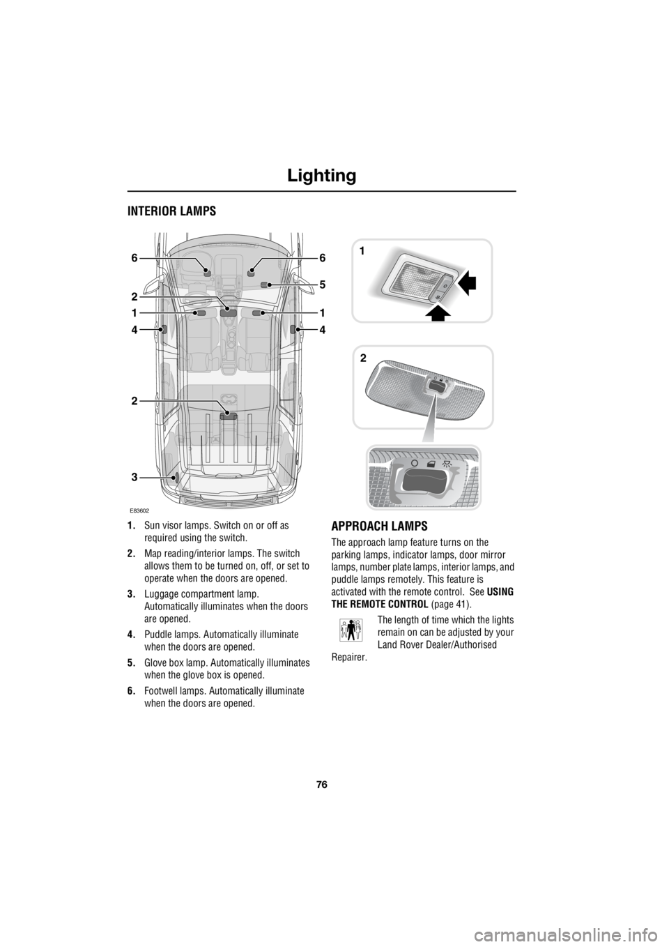
INTERIOR LAMPS
1. Sun visor lamps. Sw itch on or off as
required using the switch.
2. Map reading/interior lamps. The switch
allows them to be turn ed on, off, or set to
operate when the doors are opened.
3. Luggage compartment lamp.
Automatically illuminates when the doors
are opened.
4. Puddle lamps. Automatically illuminate
when the doors are opened.
5. Glove box lamp. Auto matically illuminates
when the glove box is opened.
6. Footwell lamps. Auto matically illuminate
when the doors are opened.APPROACH LAMPS
The approach lamp feature turns on the
parking lamps, indica tor lamps, door mirror
lamps, number plate lamps, interior lamps, and
puddle lamps remotely . This feature is
activated with the remote control. See USING
THE REMOTE CONTROL (page 41).
The length of time which the lights
remain on can be adjusted by your
Land Rover Dealer/Authorised
Repairer.
3
2
4
1
2
6
4
1
5
61
2
E83602