ground clearance LAND ROVER FRELANDER 2 2006 Repair Manual
[x] Cancel search | Manufacturer: LAND ROVER, Model Year: 2006, Model line: FRELANDER 2, Model: LAND ROVER FRELANDER 2 2006Pages: 3229, PDF Size: 78.5 MB
Page 451 of 3229
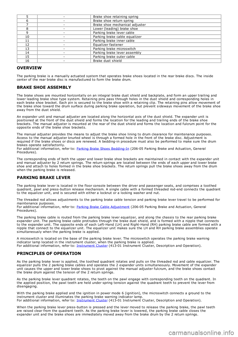
5-Brake shoe retai ni ng s pri ng
6-Brake shoe return s pri ng
7-Brake shoe mechanical adjust er8-Lower (l eadi ng) brake s hoe
9-Parki ng brake l ever cabl e
10-Parki ng brake cabl e equalizer11-Parki ng brake i nner cabl e
12-Equali zer fas t ener
13-Parki ng brake mi cros wit ch14-Parki ng brake l ever as sembl y
15-Parki ng brake outer cable
16-Brake dus t s hield
OVERVIEW
The parking brake is a manual ly actuat ed s ys t em t hat operat es brake s hoes located i n t he rear brake di scs . The ins idecent er of the rear brake dis c is manufact ured t o form the brake drum.
BRAKE SHOE ASSEMBLY
The brake s hoes are mount ed horizontal ly on an int egral brake dus t s hield and backplat e, and form an upper t rai li ng andlower l eading brake s hoe type s yst em. Retai ni ng pins pas s t hrough hol es in the dus t s hield and corres ponding hol es ineach brake s hoe bracket . Each pi n is secured t o t he brake s hoe wit h a ret ai ning cli p. The ret ai ning pins al low movement oft he brake s hoe toward the drum surface duri ng parking brake operat ion, but prevent si deways movement of the brake shoeaway from the dus t s hi eld.
An expander unit and manual adjust er are l ocat ed along t he hori zont al axis of t he dus t shi el d. The expander uni t isposi ti oned at the front of the dus t s hield and forms t he locati on for t he leading and t rai ling ends of t he brake s hoebracket s . The manual adjus t er i s mounted at t he rear of t he dust s hiel d and forms t he l ocati on and ful crum poi nt for theoppos it e ends of t he brake s hoe bracket s.
The manual adjus t er provides the means to adjust t he brake s hoe l ining t o drum clearance for maintenance purposes .Acces s t o t he manual adjus t er knurl ed wheel i s t hrough a formed hole in the front of the brake dis c. Adjust ment isrequired if t he brake s hoes or dis cs are renewed. A bedding-in procedure must al so be performed t o make s ure the drumbrakes operate sat is fact oril y.For addit ional informat ion, refer t o: Parking Brake Shoes Bedding-In (206-05 Parking Brake and Actuati on, GeneralProcedures).
The corres pondi ng ends of bot h t he upper and l ower brake shoe brackets are mai ntained i n contact wit h t he expander uni tand manual adjus t er by 2 ret urn springs . The return s pri ngs are l ocat ed bet ween t he ends of each upper and l ower brakes hoe and att ach to hol es formed in the brake shoe brackets . The ret urn springs pull t he brake s hoes away from t he drumwhen t he parking brake is released.
PARKING BRAKE LEVER
The parking brake lever is l ocat ed in t he floor cons ole bet ween the driver and pass enger s eats , and compri ses a toot hedquadrant , pawl and pres s-butt on rel eas e mechanis m. A si ngl e cabl e wi th a formed t hreaded rod-end connect s t he quadrantt o the equali zer unit , and is secured wit h eit her a locknut or a l ocking was her and nut.
The t hreaded rod all ows adjus tment s t o t he parking brake cable tens ion and parki ng brake lever travel t o be performed formaint enance purpos es.For addit ional informat ion, refer t o: Parking Brake Cabl e Adjus tment (206-05 Parki ng Brake and Actuat ion, GeneralProcedures).
The parking brake cable is routed from t he parking brake l ever equalizer, and al ong the chas si s t o t he rear parking brakeexpander uni t. The parki ng brake cabl e prot rudes t hrough t he brake dust s hiel d, and is formed wit h a nippl e that connectst o the expander unit . The oppos i te ends of each Left-Hand (LH) and Ri ght -Hand (RH) parking brake cabl e are formed wit h anipple that connect to the equali zer unit . The equal izer uni t makes sure t he LH and RH parki ng brake as s embl ies operat es imul taneous l y when the parking brake i s applied.
A micros wit ch is locat ed on t he base of the parki ng brake lever. The micros wit ch operates t he parking brake warni ngindicat or l amp l ocat ed in t he i ns t rument clus ter, when the parki ng brake i s appl ied.For addit ional informat ion, refer t o: Ins t rument Clus ter (413-01 Inst rument Cl us t er, Des cript ion and Operat ion).
PRINCIPLES OF OPERATION
As t he parking brake lever i s applied, t he toot hed quadrant rotat es and pul ls on the t hreaded rod and cable equali zer. Theequal izer pul ls t he 2 parki ng brake cables and operat es the 2 expander uni ts s i mult aneous ly. Movement of t he expanderunit caus es t he upper and l ower brake s hoes t o pivot agains t the manual adjus ter fulcrum, and t he brake s hoes cont actt he brake drum agai nst t he t ens i on of the 2 ret urn s pri ngs .
As t he parking brake lever quadrant rot ates , t he teet h on t he pawl engage wit h corresponding t eeth on the quadrant . Int he appl ied pos it ion, the pawl t eet h are held under spring t ensi on agai nst the quadrant teet h t o prevent the l ever fromdis engagi ng.
W i th the parki ng brake appli ed and the i gnit ion i n power mode 6 (ignit ion), t he mi cros wit ch connect s a ground to theins t rument clus ter and il lumi nat es t he parking brake warning i ndi cat or lamp.For addit ional informat ion, refer t o: Ins t rument Clus ter (413-01 Inst rument Cl us t er, Des cript ion and Operat ion).
W hen t he parking brake lever pres s-butt on is pres sed and t he l ever moved t o rel eas e t he parki ng brake, t he pawl teet hare rais ed clear from the quadrant t eet h. As the parki ng brake l ever i s lowered, t he parking brake cable cl oses t heexpander uni t and the brake s hoes are immediatel y moved away from the brake drum by the 2 ret urn s pri ngs .
Page 652 of 3229
Publi s hed: 11-May-2011
Engine - I6 3.2L Petrol - Valve Clearance Adjustment
General Procedures
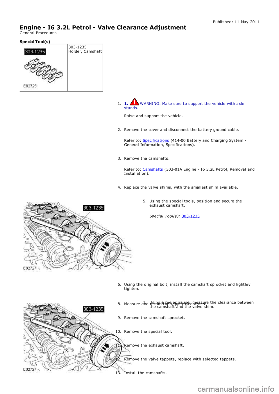
Special T ool(s) 303-1235
Hol der, Camshaft
1. W ARNING: Make sure t o s upport the vehicle wit h axle
s tands .
Rais e and s upport t he vehi cl e.
1.
Remove t he cover and dis connect the bat tery ground cabl e.
Refer t o: Specificati ons (414-00 Bat tery and Charging Sys tem -
General Informat ion, Specificati ons).
2.
Remove t he camshaft s .
Refer t o: Camshafts (303-01A Engine - I6 3.2L Pet rol , Removal and
Inst all at ion).
3.
Replace t he val ve s hi ms , wit h t he s mall es t s him avai lable.
4. Us ing t he s peci al t ools , posi ti on and s ecure the
exhaus t cams haft.
Speci al Tool (s ): 303-1235 5.
Us ing t he original bol t, i nst all t he camshaft sprocket and li ght ley
t ighten.
6. Us ing a feeler gauge, meas ure the cl earance bet ween
t he camshaft and the valve s him.
7.
Meas ure and record t he tappet cl earances .
8.
Remove t he camshaft sprocket.
9.
Remove t he s pecial t ool .
10.
Remove t he exhaus t cams haft .
11.
Remove t he val ve tappets , repl ace wit h s elect ed t appet s.
12.
Inst all t he camshaft s .
13.
Page 654 of 3229
Publi s hed: 11-May-2011
Engine - I6 3.2L Petrol - Valve Clearance Check
General Procedures
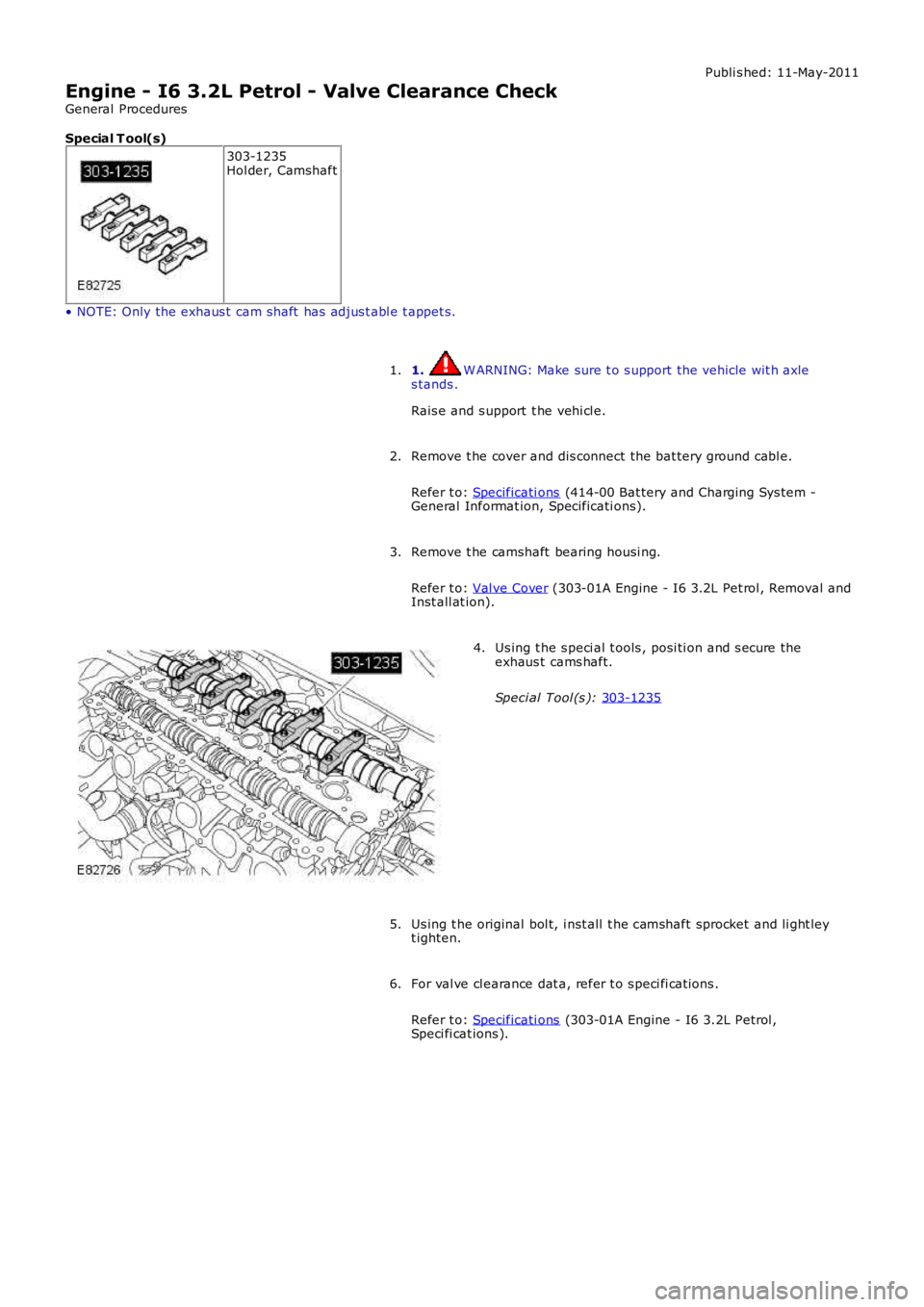
Special T ool(s) 303-1235
Hol der, Camshaft
• NOTE: Only the exhaus t cam shaft has adjus t abl e t appet s. 1. W ARNING: Make sure t o s upport the vehicle wit h axle
s tands .
Rais e and s upport t he vehi cl e.
1.
Remove t he cover and dis connect the bat tery ground cabl e.
Refer t o: Specificati ons (414-00 Bat tery and Charging Sys tem -
General Informat ion, Specificati ons).
2.
Remove t he camshaft bearing housi ng.
Refer t o: Val ve Cover (303-01A Engine - I6 3.2L Pet rol , Removal and
Inst all at ion).
3. Us ing t he s peci al t ools , posi ti on and s ecure the
exhaus t cams haft.
Speci al Tool (s ): 303-1235 4.
Us ing t he original bol t, i nst all t he camshaft sprocket and li ght ley
t ighten.
5.
For val ve cl earance dat a, refer t o s peci fi cat ions .
Refer t o: Specificati ons (303-01A Engine - I6 3.2L Petrol ,
Speci fi cat ions ).
6.
Page 672 of 3229
Publi s hed: 11-May-2011
Engine - I6 3.2L Petrol - Camshafts
Removal and Inst all ati on
Removal
1. W ARNING: Make sure t o s upport the vehicle wit h axles tands .
Rais e and s upport t he vehi cl e.
1.
Remove t he cover and dis connect the bat tery ground cabl e.
Refer t o: Specificati ons (414-00 Bat tery and Charging Sys tem -General Informat ion, Specificati ons).
2.
Remove t he camshaft bearing housi ng.
Refer t o: Val ve Cover (303-01A Engine - I6 3.2L Pet rol , Removal andInst all at ion).
3.
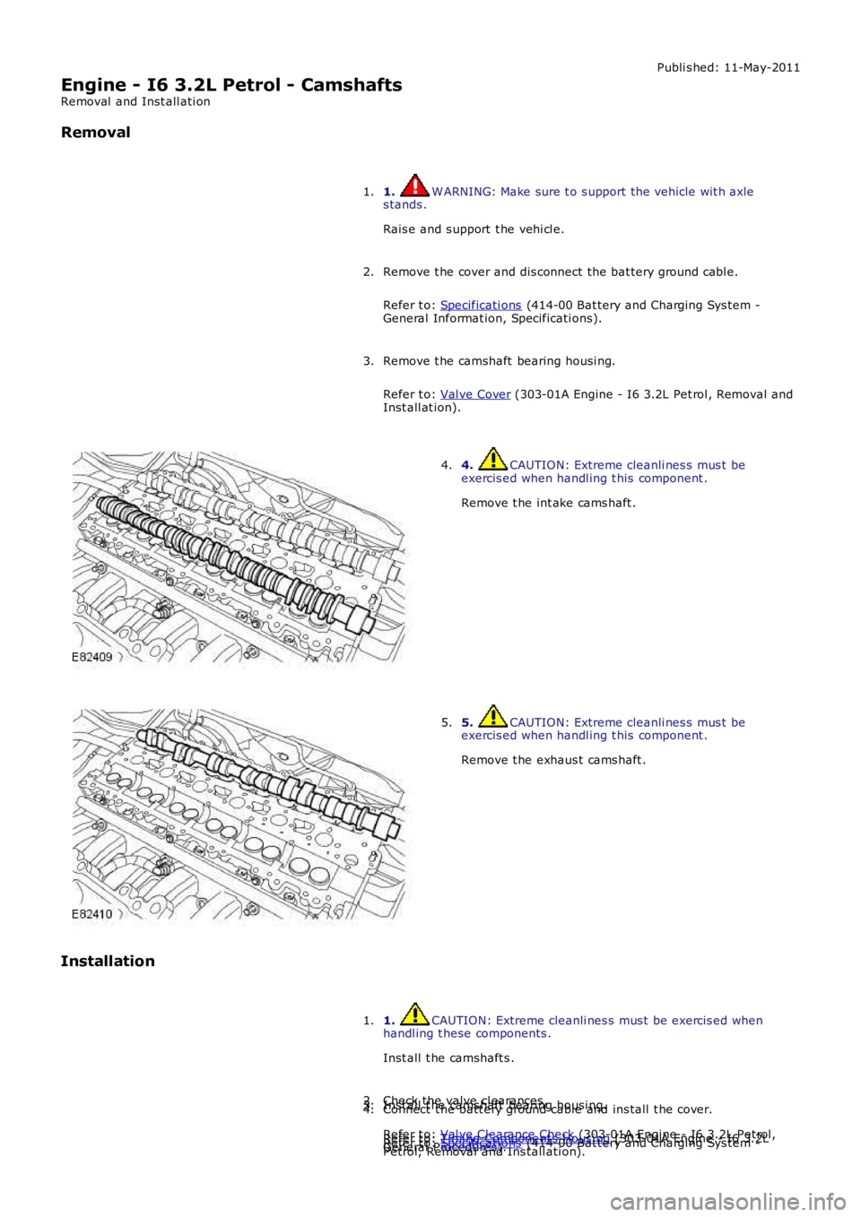
4. CAUTION: Extreme cleanli nes s mus t beexercis ed when handl ing t his component .
Remove t he int ake cams haft .
4.
5. CAUTION: Extreme cleanli nes s mus t beexercis ed when handl ing t his component .
Remove t he exhaus t cams haft .
5.
Installation
1. CAUTION: Extreme cleanli nes s mus t be exercis ed whenhandl ing t hese components .
Inst all t he camshaft s .
1.
Check the valve cl earances .
Refer t o: Val ve Clearance Check (303-01A Engine - I6 3.2L Petrol ,General Procedures).
2.Inst all t he camshaft bearing housi ng.
Refer t o: Timi ng Component s Hous i ng (303-01A Engine - I6 3.2LPetrol, Removal and Ins tall ati on).
3.Connect t he batt ery ground cable and ins tall t he cover.
Refer t o: Specificati ons (414-00 Bat tery and Charging Sys tem -
4.
Page 692 of 3229
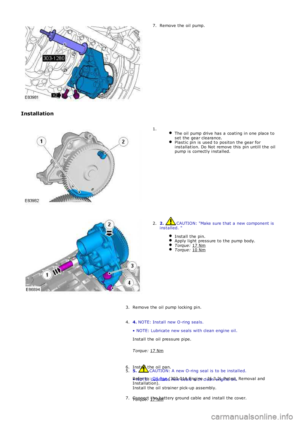
Remove t he oil pump.
7.
Installation
The oil pump drive has a coat ing i n one place t o
s et the gear clearance. Plas t ic pin is us ed t o posi ton the gear for
i ns t allat ion. Do Not remove this pin unt ill t he oil
pump i s correct ly i nst all ed. 1.
2. CAUTION: "Make sure t hat a new component is
i ns t alled. "
Inst all t he pin. Apply l ight pres s ure t o t he pump body.
T orque:
17 Nm T orque:
10 Nm 2.
Remove t he oil pump l ocking pi n.
3.
4. NOTE: Ins t al l new O-ri ng seal s.
• NOTE: Lubri cat e new s eals wi th cl ean engi ne oil .
Inst all t he oil pres s ure pi pe.
T orque: 17 Nm 4.
5. CAUTION: A new O-ring seal is to be ins tall ed.
• NOTE: Lubri cat e new s eals wi th cl ean engi ne oil .
Inst all t he oil s trainer pick-up as sembl y.
T orque: 17 Nm 5.
Inst all t he oil pan.
Refer t o: Oil Pan (303-01A Engi ne - I6 3.2L Pet rol, Removal and
Inst all at ion).
6.
Connect t he batt ery ground cable and ins tall t he cover.
7.
Page 2756 of 3229
Introduction
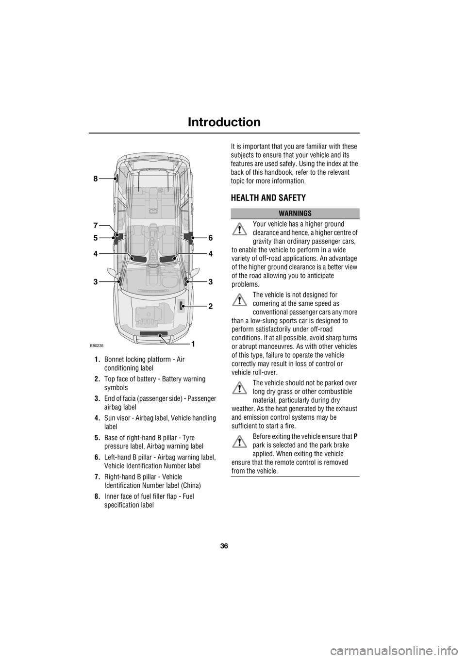
36
L
1. Bonnet locking platform - Air
conditioning label
2. Top face of battery - Battery warning
symbols
3. End of facia (passenger side) - Passenger
airbag label
4. Sun visor - Airbag label, Vehicle handling
label
5. Base of right-hand B pillar - Tyre
pressure label, Ai rbag warning label
6. Left-hand B pillar - Airbag warning label,
Vehicle Identification Number label
7. Right-hand B pillar - Vehicle
Identification Number label (China)
8. Inner face of fuel filler flap - Fuel
specification label It is important that you are familiar with these
subjects to ensure that your vehicle and its
features are used safely. Using the index at the
back of this handbook, re fer to the relevant
topic for more information.
HEALTH AND SAFETY
E80235
6
4
3
2
1
5
4
3
8
7
WARNINGS
Your vehicle has a higher ground
clearance and hence, a higher centre of
gravity than ordina ry passenger cars,
to enable the vehicle to perform in a wide
variety of off-road app lications. An advantage
of the higher ground clea rance is a better view
of the road allowing you to anticipate
problems.
The vehicle is not designed for
cornering at the same speed as
conventional passenge r cars any more
than a low-slung sports car is designed to
perform satisfactori ly under off-road
conditions. If at all possible, avoid sharp turns
or abrupt manoeuvres. As with other vehicles
of this type, failure to operate the vehicle
correctly may result in loss of control or
vehicle roll-over.
The vehicle should no t be parked over
long dry grass or other combustible
material, particul arly during dry
weather. As the heat ge nerated by the exhaust
and emission control systems may be
sufficient to start a fire.
Before exiting the vehicle ensure that P
park is selected and the park brake
applied. When exiting the vehicle
ensure that the remote control is removed
from the vehicle.