wheel bolts LAND ROVER FRELANDER 2 2006 Repair Manual
[x] Cancel search | Manufacturer: LAND ROVER, Model Year: 2006, Model line: FRELANDER 2, Model: LAND ROVER FRELANDER 2 2006Pages: 3229, PDF Size: 78.5 MB
Page 17 of 3229
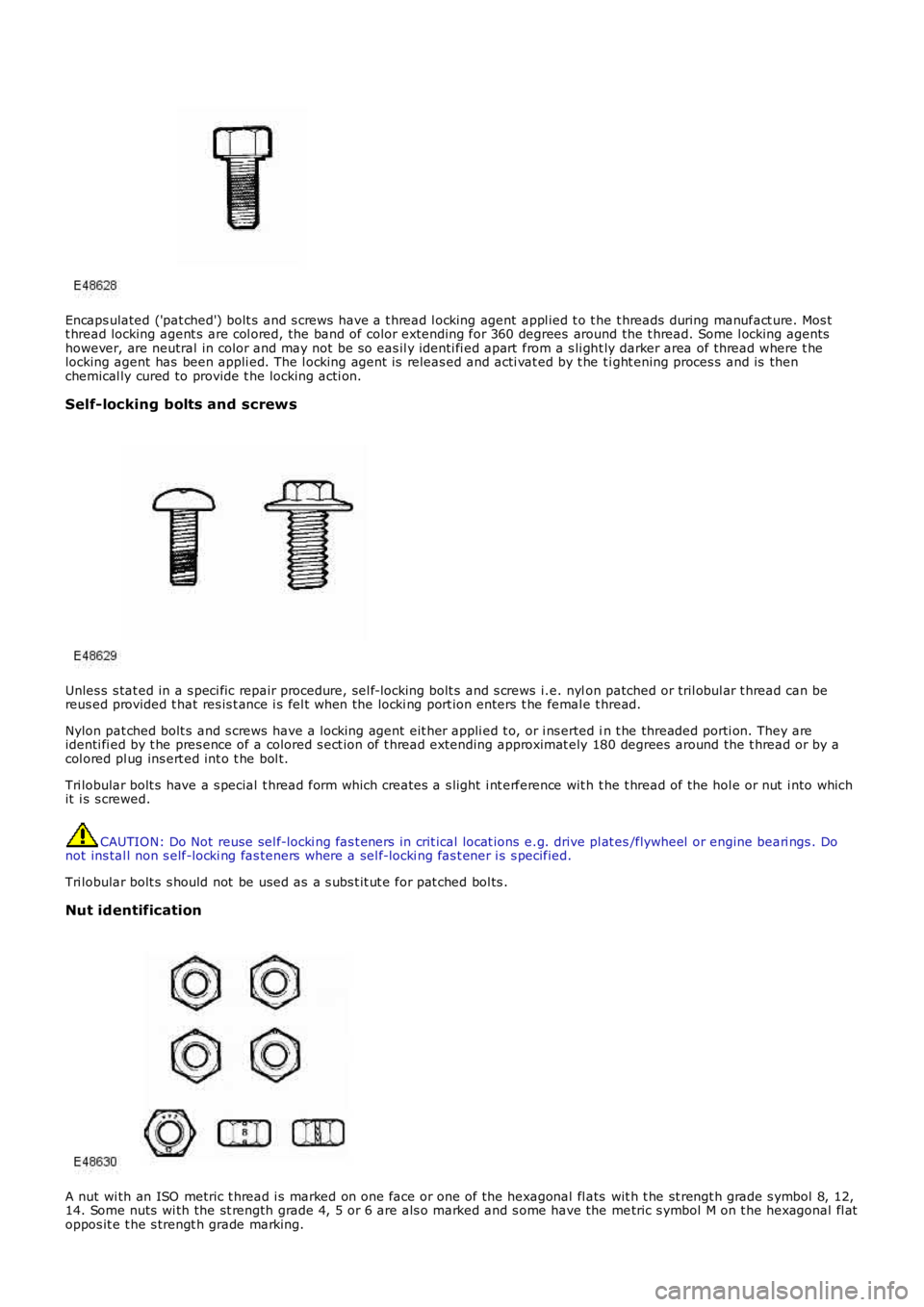
Encaps ulated ('pat ched') bolt s and s crews have a t hread l ocking agent appl ied t o t he t hreads during manufact ure. Mos tt hread locking agent s are col ored, the band of color extending for 360 degrees around the t hread. Some l ocking agentshowever, are neutral in color and may not be s o eas il y identi fi ed apart from a s li ght ly darker area of thread where t helocking agent has been appli ed. The l ocking agent is releas ed and acti vat ed by t he ti ght ening proces s and is thenchemical ly cured to provide t he locking acti on.
Self-locking bolts and screws
Unles s s tat ed in a s peci fic repair procedure, sel f-locki ng bolt s and s crews i.e. nylon patched or tril obul ar t hread can bereus ed provided t hat res is t ance i s fel t when the locki ng port ion enters t he femal e thread.
Nylon pat ched bolt s and s crews have a l ocking agent eit her appli ed t o, or i ns erted in t he threaded porti on. They areidenti fi ed by t he pres ence of a colored s ect ion of t hread extending approximat ely 180 degrees around the t hread or by acol ored pl ug ins ert ed int o t he bol t.
Tri lobular bolt s have a s pecial t hread form which creates a s light i nt erference wit h t he t hread of the hol e or nut i nto whichit i s s crewed.
CAUTION: Do Not reuse sel f-locki ng fas t eners in crit ical locat ions e.g. drive pl at es/flywheel or engine beari ngs . Donot ins tal l non s elf-locki ng fas teners where a sel f-locki ng fas t ener i s s pecified.
Tri lobular bolt s s hould not be used as a s ubs t it ut e for pat ched bol ts .
Nut identification
A nut wi th an ISO metric t hread i s marked on one face or one of the hexagonal fl ats wit h t he st rengt h grade s ymbol 8, 12,14. Some nuts wi th the st rength grade 4, 5 or 6 are als o marked and s ome have the metric s ymbol M on t he hexagonal fl atoppos it e t he s trengt h grade marking.
Page 420 of 3229
Publi s hed: 11-May-2011
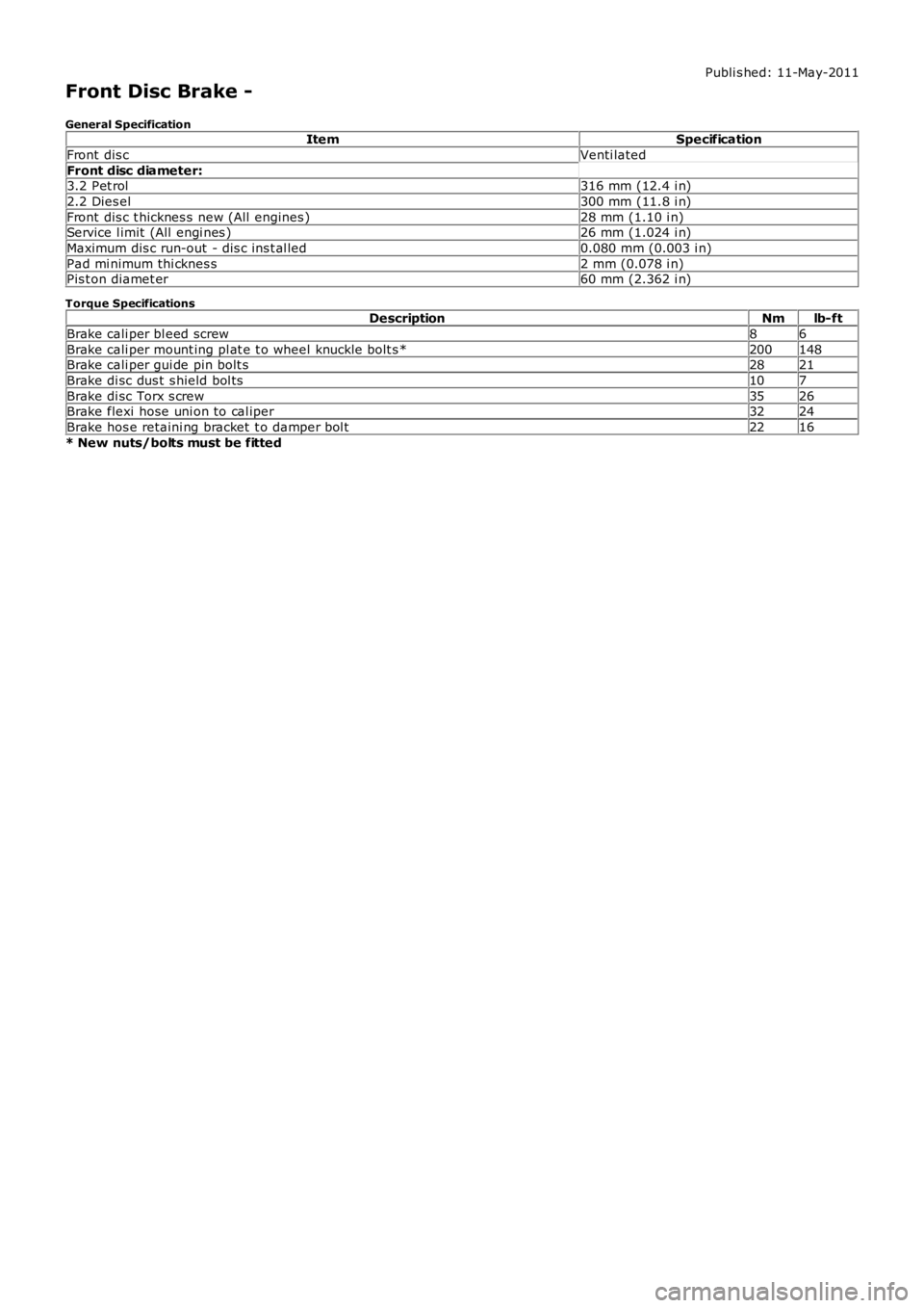
Front Disc Brake -
General SpecificationItemSpecification
Front dis cVenti lated
Front disc diameter:3.2 Pet rol316 mm (12.4 i n)
2.2 Dies el300 mm (11.8 i n)
Front dis c t hicknes s new (All engines )28 mm (1.10 i n)Service l imit (All engi nes )26 mm (1.024 i n)
Maximum dis c run-out - dis c ins t al led0.080 mm (0.003 i n)
Pad mi nimum thi cknes s2 mm (0.078 i n)Pis t on diamet er60 mm (2.362 i n)
Torque SpecificationsDescriptionNmlb-ft
Brake cali per bl eed screw86
Brake cali per mount ing pl at e t o wheel knuckle bolt s *200148Brake cali per gui de pin bolt s2821
Brake di sc dus t s hield bol ts107
Brake di sc Torx s crew3526Brake flexi hose uni on to cal iper3224
Brake hos e retaini ng bracket t o damper bol t2216
* New nuts/bolts must be fitted
Page 433 of 3229
Publi s hed: 11-May-2011
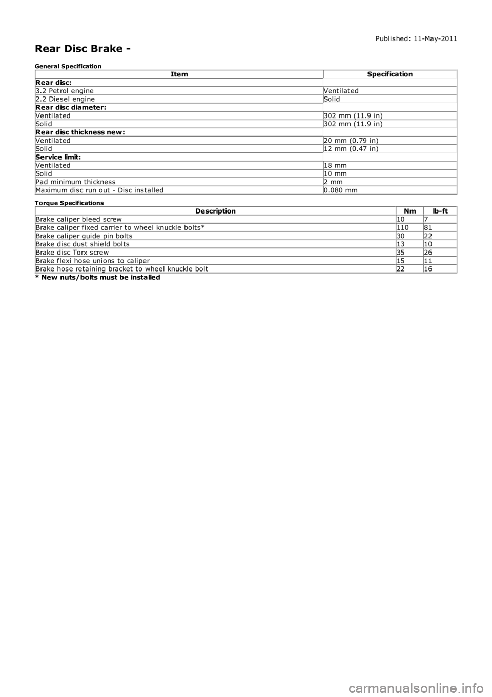
Rear Disc Brake -
General SpecificationItemSpecification
Rear disc:
3.2 Pet rol engineVent il at ed2.2 Dies el engineSol id
Rear disc diameter:
Venti lat ed302 mm (11.9 in)Soli d302 mm (11.9 in)
Rear disc thickness new :
Venti lat ed20 mm (0.79 in)Soli d12 mm (0.47 in)
Service limit:
Venti lat ed18 mmSoli d10 mm
Pad mi nimum thi cknes s2 mm
Maximum dis c run out - Dis c ins t al led0.080 mm
Torque Specifications
DescriptionNmlb-ftBrake cali per bl eed screw107
Brake cali per fixed carrier t o wheel knuckl e bolt s*11081
Brake cali per gui de pin bolt s3022Brake di sc dus t s hield bol ts1310
Brake di sc Torx s crew3526
Brake flexi hose uni ons to cali per1511Brake hos e retaini ng bracket t o wheel knuckle bolt2216
* New nuts/bolts must be installed
Page 570 of 3229
Publi s hed: 11-May-2011
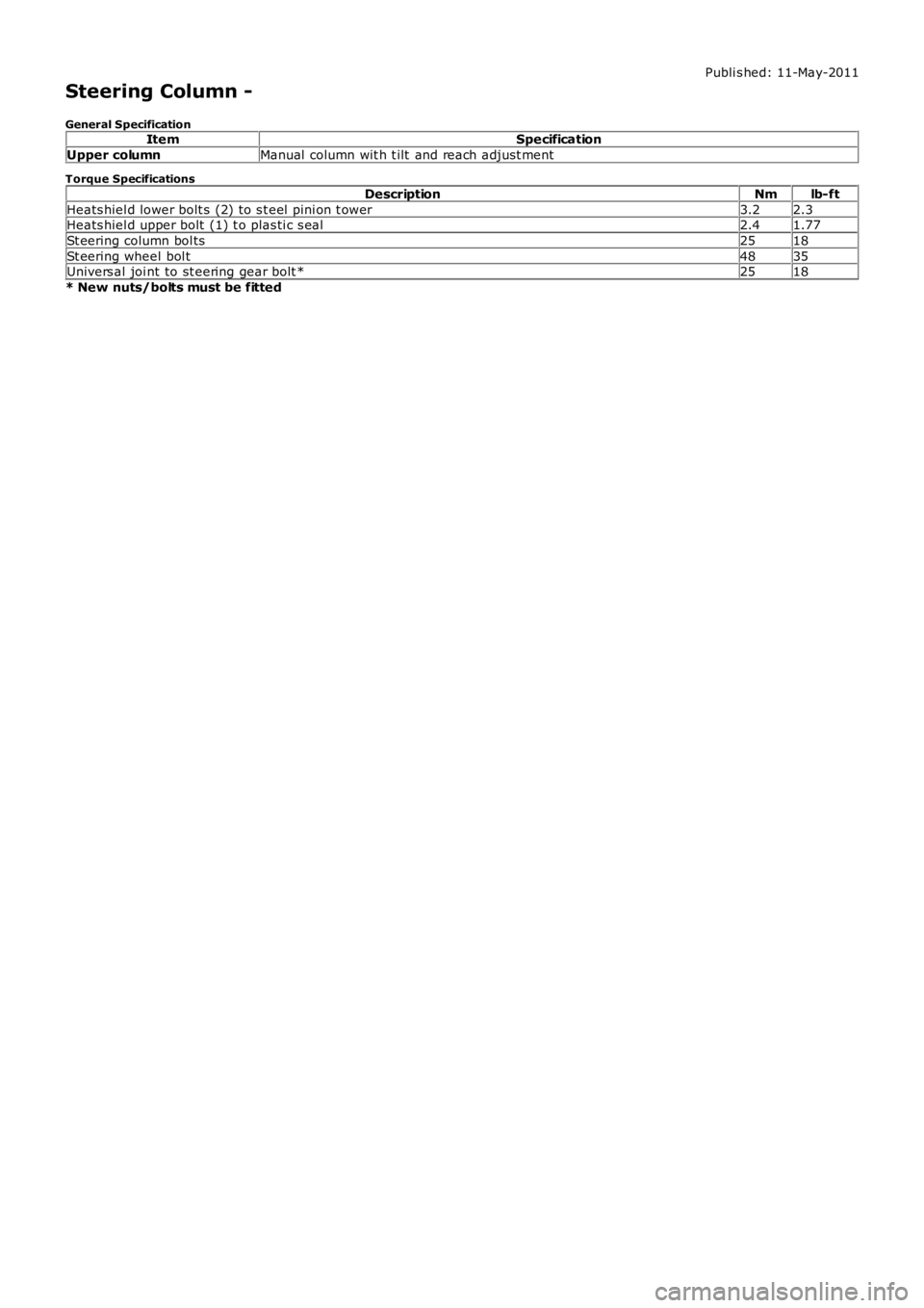
Steering Column -
General SpecificationItemSpecification
Upper columnManual column wit h t ilt and reach adjust ment
Torque Specifications
DescriptionNmlb-ft
Heats hiel d lower bolt s (2) to s t eel pi ni on t ower3.22.3Heats hiel d upper bolt (1) t o plas ti c s eal2.41.77
St eering column bol ts2518
St eering wheel bol t4835Univers al joi nt to st eering gear bolt *2518
* New nuts/bolts must be fitted
Page 604 of 3229
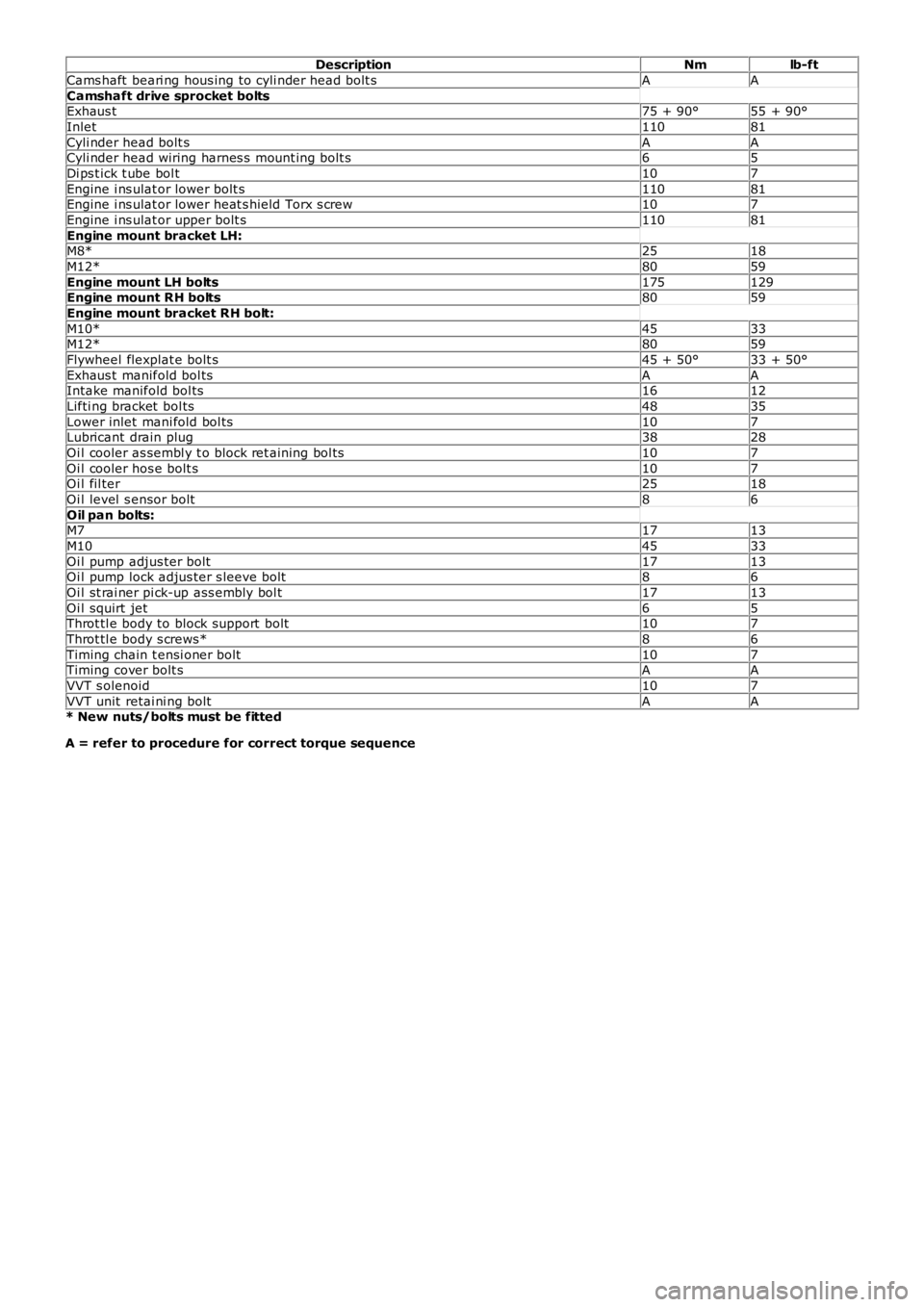
DescriptionNmlb-ft
Cams haft beari ng hous ing to cyli nder head bolt sAA
Camshaft drive sprocket boltsExhaus t75 + 90°55 + 90°
Inlet11081
Cyli nder head bolt sAACyli nder head wiring harnes s mount ing bolt s65
Di ps t ick t ube bol t107
Engine i ns ulat or lower bolt s11081Engine i ns ulat or lower heat s hield Torx s crew107
Engine i ns ulat or upper bolt s11081
Engine mount bracket LH:M8*2518
M12*8059
Engine mount LH bolts175129Engine mount RH bolts8059
Engine mount bracket RH bolt:
M10*4533M12*8059
Flywheel flexplat e bolt s45 + 50°33 + 50°
Exhaus t manifold bol tsAAIntake manifold bol ts1612
Lifti ng bracket bol ts4835
Lower inlet mani fold bol ts107Lubricant drain plug3828
Oi l cooler as sembl y t o block ret aining bol ts107
Oi l cooler hos e bolt s107Oi l fil ter2518
Oi l level s ensor bolt86
Oil pan bolts:M71713
M104533
Oi l pump adjus ter bolt1713Oi l pump lock adjus ter s leeve bolt86
Oi l st rai ner pi ck-up ass embly bol t1713
Oi l squirt jet65Throt tl e body to block support bolt107
Throt tl e body s crews*86
Timing chain t ensi oner bolt107Timing cover bolt sAA
VVT s olenoid107
VVT unit retai ni ng boltAA* New nuts/bolts must be fitted
A = refer to procedure for correct torque sequence
Page 753 of 3229
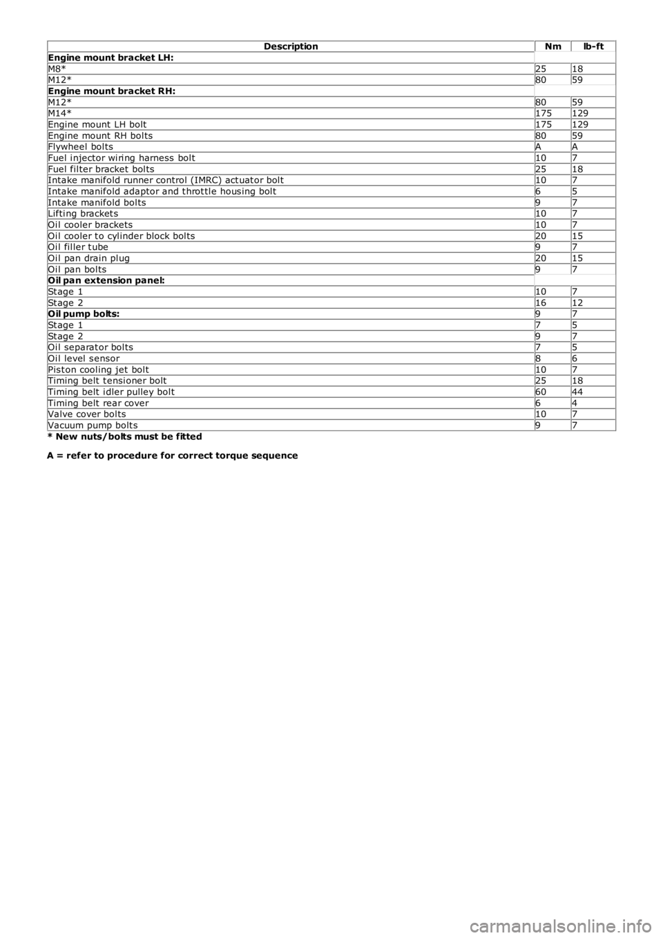
DescriptionNmlb-ft
Engine mount bracket LH:
M8*2518M12*8059
Engine mount bracket RH:
M12*8059M14*175129
Engine mount LH bolt175129
Engine mount RH bol ts8059Flywheel bol tsAA
Fuel i njector wi ri ng harness bol t107
Fuel fil ter bracket bol ts2518Intake manifold runner control (IMRC) act uat or bol t107
Intake manifold adaptor and t hrot tl e hous i ng bol t65
Intake manifold bol ts97Lifti ng bracket s107
Oi l cooler brackets107
Oi l cooler t o cyl inder block bol ts2015Oi l fil ler t ube97
Oi l pan drain pl ug2015
Oi l pan bol ts97Oil pan extension panel:
St age 1107
St age 21612Oil pump bolts:97
St age 175
St age 297Oi l separat or bol ts75
Oi l level s ensor86
Pis t on cool ing jet bol t107Timing belt t ensi oner bolt2518
Timing belt i dler pulley bol t6044
Timing belt rear cover64Valve cover bol ts107
Vacuum pump bolt s97
* New nuts/bolts must be fitted
A = refer to procedure for correct torque sequence
Page 1409 of 3229
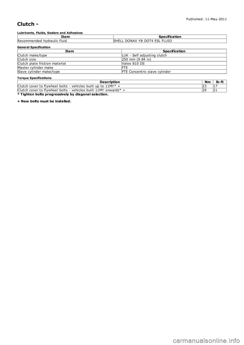
Publi s hed: 11-May-2011
Clutch -
Lubricants, Fluids, Sealers and AdhesivesItemSpecification
Recommended hydraul ic fluidSHELL DONAX Y B DOT4 ESL FLUID
General Specification
ItemSpecification
Clut ch make/t ypeLUK - Self adjus ti ng clutchClut ch s ize250 mm (9.84 in)
Clut ch plat e frict ion mat eri alVal eo 810 DS
Mas ter cylinder makeFTESlave cyli nder make/t ypeFTE Concent ric s lave cylinder
Torque Specifications
DescriptionNmlb-ft
Clut ch cover t o fl ywheel bolt s - vehi cles buil t up to 11MY * +2317Clut ch cover t o fl ywheel bolt s - vehi cles buil t 11MY onwards* +2921
* T ighten bolts progressively by diagonal selection.
+ New bolts must be installed.
Page 2607 of 3229
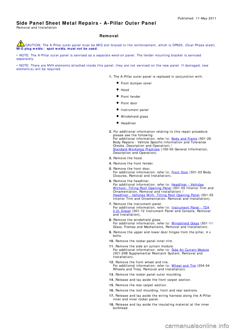
Publ is hed: 11-May-2011
Side Panel Sheet Metal Repairs - A-Pillar Outer Panel
Removal and Installation
Removal
CAUTION: The A-Pillar outer panel must be MIG slot brazed to the reinforcement, which is DP600, (Dual Phase steel).
MIG plug we lds / spot we lds, must not be used.
• NOTE: The A-Pillar outer panel is serviced as a separate weld-on panel. The fender mounting bracket is serviced
separately.
• NOTE: There are NVH elements attached inside this panel; they are not serviced on the new panel. If damaged, new
element(s) will be required.
1. The A-Pillar out er panel is replaced in conjunct ion wit h:
Front bumper cover
Hood
Front fender
Front door
Instrument panel
Windshield glass
Headliner
2. Fo r a d d i t i o na l i nf o rma t i o n re l a t i ng t o t hi s re p a i r p ro ce d ure
please see the following:
Fo r a d d i t i o na l i nf o rma t i o n, re f e r t o : Body and Frame
(501-26
Body Repairs - Vehicle Specific Information and Tolerance
Checks, Description and Operation) /
St a nd a rd W o rks ho p P ra ct i ce s
(100-00 Ge ne ra l I nf o rma t i o n,
Description and Operation).
3. Remove the hood.
4. Remove the front fender.
5. Remove the front door.
Fo r a d d i t i o na l i nf o rma t i o n, re f e r t o : Front Door
(501-03 Body
Closures, Removal and Installation).
6. Remove the headliner.
Fo r a d d i t i o na l i nf o rma t i o n, re f e r t o : Headliner - Vehicles
Without: Tilting Roof Opening Panel (501-05 Int eri or Tri m and
Ornamentation, Removal and Installation) /
Headliner - Vehicles With: Tilting Roof Opening Panel
(501-05
Int erior Trim and Ornamentat ion, Removal and Installat ion).
7. Re move t he i ns t rume nt pa ne l .
Fo r a d d i t i o na l i nf o rma t i o n, re f e r t o : Instrument Panel - TD4
2.2L Di es el (501-12 Ins t rument Panel and Cons ole, Removal
and Installation).
8. Remove the windshield glass.
Fo r a d d i t i o na l i nf o rma t i o n, re f e r t o : Windshield Glass
(501-11
Glass, Frames and Mechanisms, Removal and Installation).
9. Remove t he upper and l ower door hi nges from t he pi l lar, 4 x
bolts.
10. Re mo ve t he ro cke r p a ne l i nne r t ri m.
11. Re mo ve t he s i d e a i r curt a i n mo d ul e .
Fo r a d d i t i o na l i nf o rma t i o n, re f e r t o : Si d e A i r Curt a i n Mo d ul e
(501-20B Suppl ement al Res t rai nt Sys t em, Removal and
Installation).
12. Remove the front wheel and tire.
Fo r a d d i t i o na l i nf o rma t i o n, re f e r t o : Wheel and Tire
(204-04
Wheels and Tires, Removal and Installation).
13. Remove the rocker panel outer moulding.
14. Release and lay aside the front carpet section.
15. Re mo ve t he re a r ca rp e t s e ct i o n.
16. Remove the roof moulding, front and rear sections.
17. Release and lay aside the wiring harness along the A-Pillar
i nne r a nd i nne r ro cke r p a ne l .
18. Release and lay aside the insulating material at the inner
bulkhead.
Page 2704 of 3229
18. WARNING: Make sure that a new steering column flexible coupling bolt is
installed.
Connect the steering column to the steering gear.
Torque: 25 Nm18.
Connect and s ecure t he cat alys t moni t or s ens or el ect ri cal connect ors . 19.
Install the 2 subframe mounting bolts and remove the jack. 20.
Install the engine undershield.
Refer to: Engine Undershield
(501-02 Front End Body Panel s, Removal and
Installation). 21.
Install the wheels and tires.
Refer to: W heel and Tire
(204-04 W heels and Tires , Removal and Ins t all at i on). 22.
Refill and bleed the power steering.
Refer to: Power Steering System Bleeding
(211-00 St eeri ng Sys t em - General
Informat ion, General Procedures). 23.
Using only four wheel alignment equipment approved by Land Rover, check and adjust
the wheel alignment. 24.
Page 2715 of 3229
1. CAUTION: Make sure that new bolts are installed.
Clean the component mating faces.
With assistance, install the subframe.With assistance, align and secure the differential.Tighten the rear bolts.
Torque: 110 Nm
Tighten the front bolts.
Torque: 175 Nm
1.
2.
CAUTION: Make sure that new bolts are installed.
Align the suspension arms to the subframe and install the bolts, do
not fully tighten at this stage. 2.
Using the special tool, support the subframe. 3.
Connect the transmission breather lines. 4.
5. CAUTIONS:
Make sure that no components catch.
Make sure that new bolts are installed.
With assistance, position the subframe to the body and tighten the
bolts.
Torque: 175 Nm
5.
6.
CAUTION: Make sure that new bolts are installed.
Install the stabilizer clamp bolts, but do not tighten fully at this
stage. 6.
Connect the Active On-demand Coupling module electrical connector. 7.
Re mo ve t he p o we rt ra i n j a ck.
General Equi pment : P o w e rt ra i n Ja ck
8.
9.
CAUTION: Make sure that new bolts are installed.
Install the trailing arm to body brackets.
Torque: 110 Nm9.
10.
CAUTION: Make sure that the brake hose is not twisted
and is correctly located.
Clean the component mating faces.
Install the brake caliper anchor plate.
Torque: 110 Nm
Repeat the above procedure for the other side.
10.
Secure the wheel speed sensor and lead.
11.