recommended oil LAND ROVER FRELANDER 2 2006 Repair Manual
[x] Cancel search | Manufacturer: LAND ROVER, Model Year: 2006, Model line: FRELANDER 2, Model: LAND ROVER FRELANDER 2 2006Pages: 3229, PDF Size: 78.5 MB
Page 14 of 3229
Publi s hed: 11-May-2011
General Information - Standard Workshop Practices
Des cript ion and Operat ion
Vehicle in Workshop
W hen working on a vehicl e in the workshop al ways make sure t hat :
W here practi cable, t he parking brake is appli ed and t he wheel s are securely chocked to prevent t he vehi cl e movingforwards or backwards .W henever pos si ble, t he ignit ion key i s removed before any work is carried out on t he vehi cle.If the engine i s t o be run, t here i s adequat e vent il ati on, or an extract ion hos e i s us ed to remove exhaus t fumes.There i s adequat e room to rais e the vehicle and remove t he wheel s , if neces s ary.Fender covers are al ways ins tal led i f any work i s to be carri ed out in t he engine compart ment.W here practi cable, t he batt ery i s dis connected if worki ng on the engi ne, underneath t he vehicle, or if t he vehi cl e i srai sed.
• CAUTIO NS:
Prior to dis connect ing the bat tery, refer to the El ect ri cal Secti on of this manual - Bat tery dis connect ion/connect ion.For addit ional informat ion, refer t o: Specificati ons (414-01 Bat t ery, Mount ing and Cables , Speci ficat ions).
W hen el ect ri c arc wel ding on a vehi cl e, al ways dis connect t he generator wi ri ng to prevent t he pos si bili ty of a s urgeof current caus i ng damage to the i nternal component s of the generat or.
If us i ng welding equipment on t he vehicle, a s uit abl e fire exti nguis her is readily avail able.
Battery - General
• CAUTIO NS:
Prior to carrying out any procedures which i nvol ve dis connect ing/ or connecti ng the bat tery, refer t o t he ElectricalSect ion of t his manual - Batt ery di sconnect ion/connect ion.For addit ional informat ion, refer t o: Specificati ons (414-01 Bat t ery, Mount ing and Cables , Speci ficat ions).
A di s charged bat tery condit ion may have been caus ed by an electrical short ci rcuit . If t his condit ion exis t s there wil lbe an apparentl y li ve circuit on the vehicle even when al l normal circuit s are s wit ched off. This can cause arcing when t hejumper cables are connect ed.
W hi le it i s not recommended that the vehicl e is jump s t art ed, i t is recognized t hat thi s may occas ionall y be t he onl ypracti cal way t o mobi lize a vehi cl e. Prior t o at tempt ing a jump s t art , reference must be made to the El ect ri cal Secti on oft hi s manual - Jump St art ing.
Followi ng jump s tart ing of a dis abl ed vehi cle, the di s charged bat tery mus t be checked for s erviceabili ty and recharged offt he vehi cl e as s oon as poss ibl e t o avoi d permanent damage.
Do not rel y on t he generator t o res t ore a di s charged bat tery. For a generat or t o recharge a batt ery, it woul d take i n exces sof eight hours cont inuous dri vi ng wi th no addi ti onal loads placed on t he batt ery.
Always make s ure that t he jumper cabl es are adequate for the tas k.Always make s ure that t he s lave batt ery i s of the same vol tage as t he vehicle bat tery. The bat teries mus t beconnected i n paral lel.Always make s ure that s wit chabl e electric circui ts are s wi tched off before connecti ng jumper cabl es. This reducest he ri sk of arci ng occurring when the final connecti on is made.
Towing the Vehicle
W ARNING: W hen t owing i s neces sary, reference mus t be made to the Jacki ng, Lift ing and Towing Secti on of thi sManual .
W hen t he vehicle i s being t owed dock the remote cont rol and s wit ch on the ignit ion. (s t eering l ock releas ed and warni ngli ght s i ll uminated). Onl y t hen wil l the s t eering, turn s ignal lamps , horn and s t op lamps be operat ional. Fail ure t o followt hes e i nst ructi ons may res ult in pers onal injury. It mus t be noted that wit h t he engine not running, t he power s t eering andbrake boost er wil l be inoperat ive t herefore, great er effort wil l be needed t o s t eer t he vehicle and apply the brakes .
General Installation Instructions
Component removal
W henever pos si ble, clean component s and the surroundi ng area before removal .
Blank off openings expos ed by component removal .Followi ng dis connecti on, s eal fuel, oil or hydrauli c li nes i mmediat ely us ing sui table bl anki ng plugs or caps .Seal open ends of expos ed oil ways us i ng sui table tapered hardwood pl ugs or cons pi cuous pl as t ic pl ugs .Immediat el y a component i s removed, place it i n a sui table contai ner; us e a s eparate cont ai ner for each componentand it s as s ociat ed part s .
Page 16 of 3229
Woodruff keys
W oodruff keys may be reus ed provided t here i s no i ndi cat ion of wear or dis torti on.
Remove any burrs from edges of keyways us ing a fine fil e.
Split pins
Never at tempt t o s t raight en and reus e a s pli t pin, always make s ure that repl acement pins are of the correct si ze for t hehole i n which t hey are to be ins tal led.
Screw Threads
Damaged nuts , bolt s and s crews mus t always be dis carded. Att empti ng to recut or repai r damaged threads wi th at ap or di e i mpai rs the s t rength and fi t of t he t hreads and is not recommended.
• NOTE: Duri ng cert ai n repai r operat ions , it may be neces sary t o remove t races of t hread locking agent s us ing a tap.W here thi s is neces sary, t he i ns t ructi on to do s o wi ll appear in the relevant operation and it i s ess enti al that a t ap of thecorrect s ize and t hread i s used.
Some bolt s are coat ed wit h a thread locki ng agent and unles s s tat ed otherwis e, they mus t not be reus ed. Newbolt s havi ng the same part number as the original mus t always be i nst all ed. W hen nuts or bolt s are to bedis carded, t he repai r operat ion and relevant torque chart will i ncl ude an ins truct ion to that effect . Do not usepropri etary thread locki ng agent s as t hey may not meet the specificati on required. See al so Encapsul at ed('Patched') Bol ts and Screws.Always make s ure that repl acement nuts and bol ts are at leas t equal i n s trengt h t o thos e t hat they are repl acing.Cast ell ated nut s mus t not be loosened t o accept a s pli t pin except in recommended cas es when thi s forms part ofan adjus tment .Do not all ow oil or greas e t o enter bli nd holes , the hydrauli c acti on res ult ing from ti ght ening t he bolt or s tud cans plit t he housi ng and als o gi ve a fal s e torque reading.Always t ighten a nut, bolt or s crew to t he s peci fi ed torque fi gure, damaged or corroded threads can give a fals et orque reading.Nut and bolt loos ening and t ightening sequences , where gi ven, mus t ALW AY S be foll owed. Di st ort ion ofcomponents or fault y s eal ing of joints wil l res ul t if t he s equences are not fol lowed. W here an ins t ructi on is gi ven tot ighten i n s tages , thes e s tages mus t be adhered t o; do not at t empt to combi ne st ages part icul arl y where cert ains tages involve t ight eni ng by degrees.To check or re-t ighten a fi xing t o a s peci fi ed t orque, firs t loosen a quart er of a turn, t hen ret ighten to the s peci fi edt orque fi gure.Unles s ins t ructed ot herwis e, do not lubricat e bolt or nut t hreads pri or t o i nst all ing.
W here it i s s tat ed t hat bolt s and s crews may be reus ed, t he fol lowi ng procedures must be carri ed out:
Check t hat threads are undamaged.Remove all t races of locki ng agent from the threads .
CAUTION: DO NOT us e a wi re brus h; take care t hat threads are not damaged.
Make s ure t hat threads are clean and free from oil or greas e.Apply t he s pecified locki ng agent t o t he bolt t hreads .
Bolt and Nut Identification
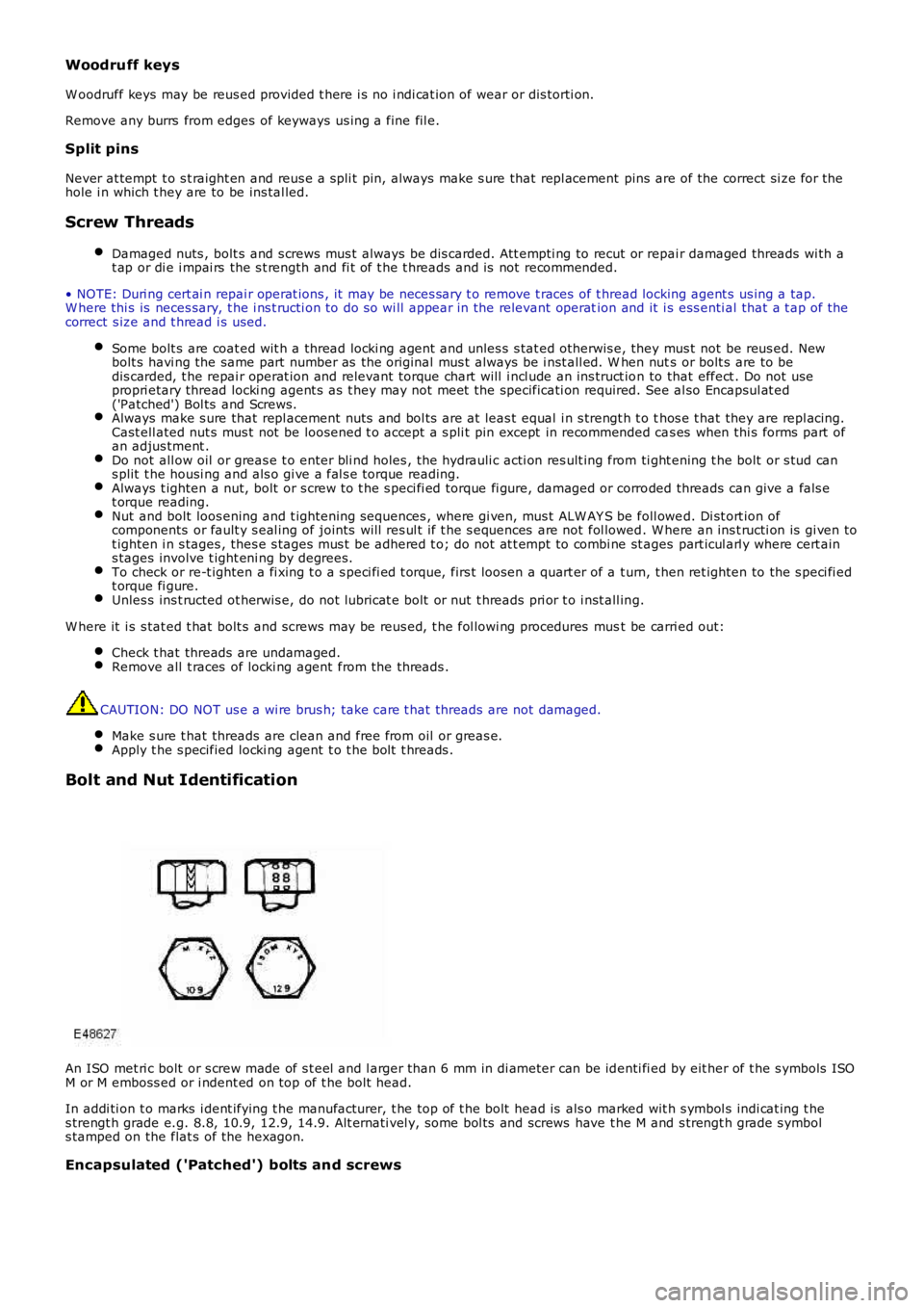
An ISO met ri c bolt or s crew made of s t eel and l arger than 6 mm in di ameter can be identi fi ed by eit her of t he s ymbols ISOM or M emboss ed or i ndent ed on top of t he bolt head.
In addi ti on t o marks i dent ifying t he manufacturer, t he top of t he bolt head is als o marked wit h s ymbol s indi cat ing t hes trengt h grade e.g. 8.8, 10.9, 12.9, 14.9. Alt ernati vel y, some bol ts and screws have t he M and s trengt h grade s ymbols tamped on the flat s of the hexagon.
Encapsulated ('Patched') bolts and screws
Page 19 of 3229
CAUTION: Service t ools have been devel oped for ins tal ling the majori ty of beari ngs ; t hese must al ways be usedwhere specified.
In the cas e of greas e l ubricated beari ngs , fil l t he s pace bet ween t he bearing and out er s eal wit h t he recommendedgrade of greas e before ins t al li ng the seal.
CAUTION: W hen a waxed oil s eal (ins tal led dry) t ype of oil s eal i s to be ins t al led, take great care that greas e doesnot cont aminate the runni ng s urface of t he s eal .
Always make s uit able reference marks bet ween t he components of s eparable bearings e.g. t aper roller beari ngswhen dis as sembl ing t o make s ure correct locati on of components when as s embli ng. Never ins tall new roll ers i n anouter ring, al ways ins tal l a new beari ng ass embly.
Brake Pads and Linings
Always i ns t all t he correct grade and s peci fi cat ion of brake pads and li nings . W hen repl acing thes e it ems , always repl ace ascomplete axl e s ets .
Brake Hydraulics
Always obs erve t he fol lowing recommendat ions when worki ng on t he braking s ys tem:
W ARNING: Do not int ermi x brake fluid of di fferent specificati ons .
Always us e t wo s panners when loos eni ng or ti ght ening brake pi pes or hos e connect ions.Make s ure t hat hos es run in a natural curve and are not kinked or twi st ed.Ins t all brake pipes and hos es s ecurel y in their retaini ng clips and make sure t hat they cannot cont act a pot enti alchafing point .Containers used for brake fluid must be kept abs ol utel y cl ean.Do not s tore brake fluid in uns ealed containers, t he fluid will abs orb wat er which wi ll lower t he boili ng point of thefl uid.Do not all ow brake flui d to be cont aminat ed wit h ot her fluids such as mi neral oil and do not put brake fl uid i n acont ainer which has previous ly been us ed for s t oring ot her fl ui ds.Do not reus e brake flui d which has been bled from t he s ys t em.Always us e brake flui d or a s uit abl e brake cleaning flui d t o clean hydraulic component s .Unles s s tat ed otherwis e, us e onl y clean brake fluid to lubri cat e hydraulic seals and components .Always i ns t all blanking plugs t o hos es, pi pes or component s immediatel y aft er dis connect ion.Check t hread compati bili ty of origi nal equipment wit h repl acement component s.Obs erve absol ute cl eanli ness when working wi th hydraul ic component s .
Pipes and Hoses
W hen removing or ins t al li ng fl exi ble hydrauli c pipes and hoses , make s ure that t he foll owing procedures are observed tomake s ure component servi ceabil it y:
Pri or to removal , clean area around hos e or pipe end which is to be dis connect ed.Obtai n appropri at e bl anking pl ugs or caps before dis connecti ng hose or pi pe end fi ttings i n order t hat connect ionscan be plugged immedi atel y fol lowing di sconnect ion.Always i ns t all blanking plugs or caps to pipes and unions immedi atel y fol lowing di sconnect ion.Clean hos e or pipe and bl ow t hrough wit h an ai r line.
W ARNING: Sui table eye protecti on mus t be worn.
Check hos es external ly for cracks , separat ion of pl ies , securi ty of end fit ti ngs and ext ernal damage; repl ace fault yhoses .Check pi pes for s igns of corros ion and chafi ng, replace as neces s ary.
CAUTION: If pipes are found to be chafed, rect ify cli ps, mount ing point s etc., to prevent furt her probl ems in service.
W hen i nst all ing hos es , make s ure that no unneces s ary bends are i ntroduced and t hat hos es are not ki nked, twi s tedor pos i ti oned cl os e t o pot ent ial chafing poi nt s .W hen i nst all ing pipes , make s ure t hat pipes are pos it ioned and cli pped cl ear of potent ial chafing point s .Always repl ace seali ng was hers i ns t alled to banjo bol ts , s ealing pl ugs etc.Always us e a backing s panner when t ightening uni ons and do not overt ight en union nuts or banjo bol ts .Aft er any work on hydraul ic s yst ems , always check for flui d leaks whil s t a s econd operat or appli es worki ng pres suret o the brake pedal or operates t he s yst em that has been worked on.
Fuel s ys tem hos es
Page 23 of 3229
t ank must be ins tall ed.
Oil seals
Never us e a seal which has been improperly st ored or handled.
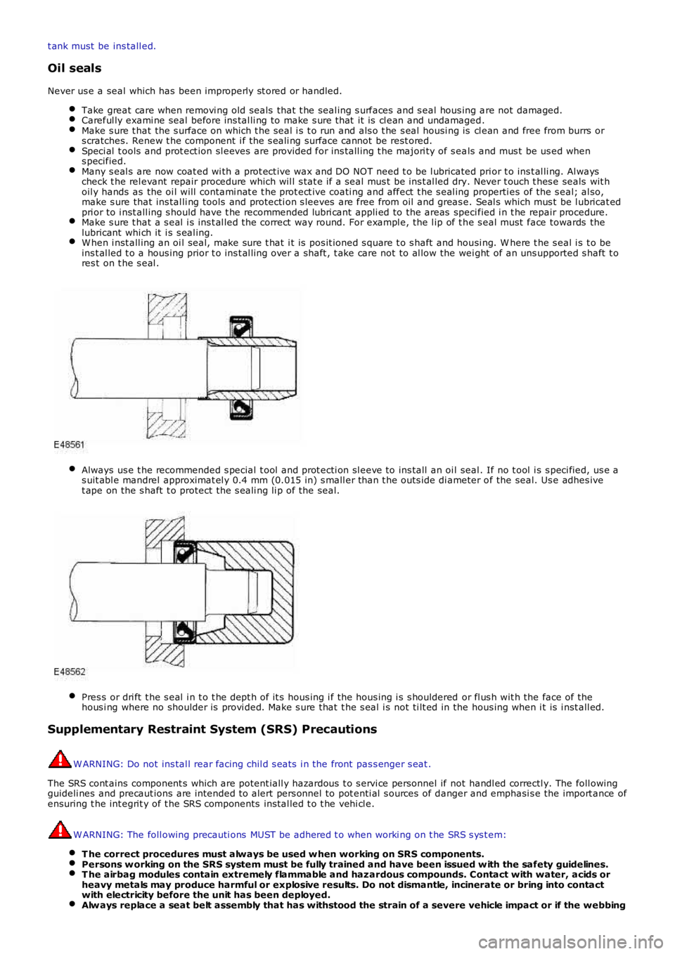
Take great care when removi ng old seals that t he seal ing s urfaces and s eal hous ing are not damaged.Careful ly exami ne seal before ins tal li ng to make s ure t hat it is cl ean and undamaged.Make s ure t hat the s urface on which t he s eal i s t o run and als o t he s eal housi ng is cl ean and free from burrs ors cratches. Renew t he component i f the s eali ng surface cannot be rest ored.Speci al t ools and prot ect ion sl eeves are provided for ins tall ing t he majori ty of s eals and mus t be us ed whens pecified.Many s eal s are now coat ed wi th a prot ect ive wax and DO NOT need t o be l ubricated prior t o ins t al li ng. Al wayscheck t he rel evant repair procedure which wil l s tat e if a seal mus t be ins t al led dry. Never t ouch t hes e seals wit hoil y hands as the oi l will contami nat e t he prot ect ive coati ng and affect t he s eal ing properti es of the s eal; al so,make s ure that ins tal li ng tools and protecti on s leeves are free from oil and greas e. Seal s which mus t be l ubricat edpri or to i nst all ing s hould have t he recommended lubri cant appli ed to the areas specified i n t he repair procedure.Make s ure t hat a s eal i s ins t al led t he correct way round. For exampl e, the l ip of t he s eal must face towards thelubricant whi ch it i s s eal ing.W hen i nst all ing an oi l seal, make sure t hat i t is pos it ioned s quare t o s haft and housi ng. W here t he s eal i s t o beins t al led t o a hous ing prior t o ins t al li ng over a shaft , t ake care not to al low the wei ght of an uns upported s haft t ores t on t he s eal .
Always us e t he recommended s pecial t ool and prot ecti on sl eeve to ins tall an oi l seal. If no t ool i s s peci fied, us e as uit abl e mandrel approximat el y 0.4 mm (0.015 in) s mall er than t he outs ide di ameter of the seal. Us e adhes ivet ape on the s haft t o protect the s eali ng li p of the seal.
Pres s or dri ft t he s eal i n t o t he dept h of it s hous ing i f the hous ing i s s houldered or fl us h wit h the face of thehous i ng where no shoulder is provi ded. Make s ure that t he s eal i s not ti lt ed in the hous ing when i t is i nst all ed.
Supplementary Restraint System (SRS) Precautions
W ARNING: Do not ins tal l rear facing chil d s eat s i n the front pas s enger s eat .
The SRS cont ains component s which are potent iall y hazardous t o s ervi ce personnel if not handl ed correctl y. The foll owingguideli nes and precaut ions are intended t o alert pers onnel to pot enti al s ources of danger and emphasi s e the import ance ofensuring t he int egrit y of t he SRS components ins tal led t o t he vehi cl e.
W ARNING: The foll owing precauti ons MUST be adhered t o when worki ng on t he SRS s ys t em:
T he correct procedures must always be used w hen working on SRS components.Persons w orking on the SRS system must be fully trained and have been issued w ith the safety guidelines.T he airbag modules contain extremely flammable and hazardous compounds. Contact with water, acids orheavy metals may produce harmful or explosive results. Do not dismantle, incinerate or bring into contactwith electricity before the unit has been deployed.Alw ays replace a seat belt assembly that has withstood the strain of a severe vehicle impact or if the webbing
Page 38 of 3229
Flammabl e - OBSERVE NO SMOKING POLICY .
Irrit at ion of t he mout h and t hroat may res ult from s wallowi ng. The main hazard from s wallowi ng ari ses if li qui d as pirat ionint o t he lungs occurs.
Liquid contact dri es the ski n and can caus e i rrit at ion or dermati ti s. Splas hes in the eye may be s light ly i rrit ati ng.
In normal circums t ances t he low vol ati lit y does not give ris e t o harmful vapors . Expos ure to mis t s and vapors fromkeros ene at el evat ed t emperature s houl d be avoi ded (mis ts may ari s e in dewaxing). Avoi d s ki n and eye cont act and makes ure t here i s adequat e vent il ati on.
If sw allow ed, DO NOT induce vomiting - SEEK IMMEDIAT E MEDICAL AT T ENT ION.
Gas Cylinders
Gas es such as oxygen, acet ylene, argon and propane are normall y s tored in cyli nders at pres s ures of up t o 138 bar (13800kPa) (2000 lbf/i n²) and great care should be taken i n handl ing t hese cyli nders t o avoi d mechani cal damage t o t hem or t ot he val ve gear at tached. The contents of each cylinder s houl d be clearl y ident ifi ed by appropri ate markings .
Cylinders should be s tored in wel l vent il at ed encl osures, and protected from ice and s now or direct sunli ght . Fuel gas es,for example acetyl ene and propane should not be st ored i n clos e proximit y t o oxygen cylinders .
Care should be exerci sed to prevent l eaks from gas cyl inders and l ines and als o t o avoid s ources of ignit ion.
Only trai ned pers onnel s houl d undertake work involving gas cyli nders .
General Workshop Tools and Equipment
It is es s ent ial t hat al l tools and equipment are maint ained in good condit ion and t he correct s afet y equi pment is us edwhere required.
Never us e t ools or equipment for any purpos e other t han that for whi ch they were desi gned. Never overl oad equi pments uch as hoi st s , jacks, axle and chas si s s tands or li ft ing sl ings . Damage caus ed by overloading i s not always immediatel yapparent and may res ult i n a fatal fai lure the next t ime that t he equi pment is us ed.
Do not us e damaged or defect ive t ools or equipment, part icularly hi gh s peed equipment s uch as gri ndi ng wheel s . Adamaged grindi ng wheel can dis int egrate wit hout warning and cause serious i njury.
W ear s uit abl e eye prot ect ion when us ing grinding, chis elli ng or s and bl ast ing equi pment .
W ear a s uit able breat hing mas k when us i ng abrasi ve blas ti ng equi pment or us i ng sprayi ng equi pment.
Make s ure t here i s adequat e vent il ati on to cont rol dust s , mis t s and fumes .
High Pressure Air, Lubrication and Oil Test Equipment
Always keep high press ure equi pment i n good condi ti on, and regul arly maint ai ned, parti cularly at joint s and uni ons.
Never di rect a high press ure nozzle, for example dies el i njector, at t he s kin as the fluid may penet rat e t o t he underlyingt is sue and caus e s eri ous i njury.
Jacking
Always refer to the Jacki ng and Lifti ng s ect ion of t hi s manual prior t o rai s ing t he vehi cl e off the ground.
W hen vehicle is t o be rais ed by means of a jack, ensure t hat i t is st andi ng on l evel ground, that parking brake is appli edand wheels are chocked. ALW AY S us e t he recommended jacking poi nt s and ens ure t hat vehi cl e jack has s ufficient loadcapacit y for t he weight of t he vehi cl e.
W ARNING: Do not work on or under a vehi cle s upported onl y by a jack. Always s upport t he vehi cl e on s afet y s tands .
Ensure t hat hois t s have s uffi ci ent load capacit y for t he wei ght of t he vehi cl e.
Legal Aspects
There are many l aws and regulat ions rel at ing to healt h and s afet y i n the us e and di spos al of materials and equipment i n aworks hop.
For a s afe worki ng envi ronment and t o avoi d environment al poll uti on, workshops s hould be famil iar, i n detai l, wi th t hemany healt h and s afety laws and regul ati ons wit hi n t hei r count ry, publ is hed by both nat ional and local aut horit ies .
Lubricants and Greases
Avoi d all prolonged and repeat ed contact wit h mi neral oils . All l ubricants and greases may be irri tat ing t o t he eyes ands ki n.
Used Engine Oil
Prol onged and repeat ed cont act wi th engi ne oil wil l res ult i n t he removal of nat ural fat s from the s kin, leading to drynes s ,irri tat ion and dermati ti s. In addit ion, used engi ne oil cont ains potent iall y harmful cont aminants whi ch may caus e s kincancer. Adequat e means of s kin protecti on and washi ng facil it ies mus t be provi ded.
Do not employ us ed engine oi ls as l ubricants or for any appli cat ion where appreciable s kin cont act i s li kel y t o occur.
Page 179 of 3229
Check t hat the flui d level is t o t he mi d-way mark between the MAX and MIN marks on t he fluid res ervoir, t op-up i fneces s ary.Clean t he area around the res ervoi r fi ll er cap, remove cap.
CAUTION: Do not fill reservoir above the MAX mark.
If necess ary, t op-up us ing t he recommended fluid to the mid-way mark on the reservoir.For addit ional informat ion, refer t o: Specificati ons (211-02 Power St eering, Specificati ons).Ins t all the res ervoir fill er cap.
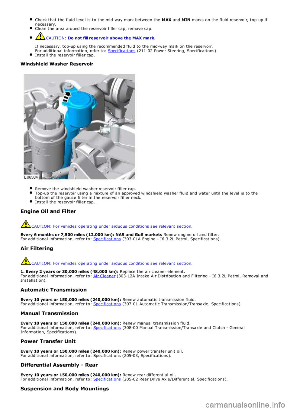
Windshield Washer Reservoir
Remove the winds hi eld was her res ervoir fill er cap.Top-up t he res ervoir us ing a mi xt ure of an approved wi nds hiel d was her flui d and water unti l the level i s t o thebott om of t he gauze fil ter i n t he res ervoir fil ler neck.Ins t all the res ervoir fill er cap.
Engine Oil and Filter
CAUTION: For vehi cl es operati ng under arduous condi ti ons s ee relevant s ecti on.
Every 6 months or 7,500 miles (12,000 km): NAS and Gulf markets Renew engi ne oil and filt er.For addit ional informat ion, refer t o: Specificati ons (303-01A Engine - I6 3.2L Petrol, Speci fi cat ions).
Air Filtering
CAUTION: For vehi cl es operati ng under arduous condi ti ons s ee relevant s ecti on.
1. Every 2 years or 30,000 miles (48,000 km): Replace the ai r cl eaner element .For addit ional informat ion, refer t o: Air Cl eaner (303-12A Int ake Ai r Dis t ri but ion and Fi lt ering - I6 3.2L Petrol , Removal andIns t allat ion).
Automatic Transmission
Every 10 years or 150,000 miles (240,000 km): Renew automat ic t rans mis s ion flui d.For addit ional informat ion, refer t o: Specificati ons (307-01 Aut omati c Trans mis s ion/Transaxle, Speci fi cat ions ).
Manual Transmission
Every 10 years or 150,000 miles (240,000 km): Renew manual t rans mi ss ion fl ui d.For addit ional informat ion, refer t o: Specificati ons (308-00 Manual Trans mis s ion/Transaxle and Clutch - GeneralInformat ion, Speci ficat ions).
Power Transfer Unit
Every 10 years or 150,000 miles (240,000 km): Renew power t rans fer unit oi l.For addit ional informat ion, refer t o: Specificati ons (205-03, Speci fi cat ions ).
Differential Assembly - Rear
Every 10 years or 150,000 miles (240,000 km): Renew rear different ial oil .For addit ional informat ion, refer t o: Specificati ons (205-02 Rear Drive Axle/Different ial, Specifi cat ions ).
Suspension and Body Mountings
Page 190 of 3229
Ensure that the steering wheel is in the straight ahead position, do not turn the st eering w heel prior to checking the
fluid level.
Check t hat the flui d level is t o t he mi d-way mark between the MAX and MIN marks on t he fluid res ervoir, t op-up i f
neces s ary. Clean t he area around the res ervoi r fi ll er cap, remove cap.
CAUTION:
Do not fill reservoir above the MAX mark.
If necess ary, t op-up us ing t he recommended fluid to the mid-way mark on the reservoi r.
For addit ional informat ion, refer t o: Specificati ons (211-02 Power St eering, Specificati ons).
Ins t all the res ervoir fill er cap.
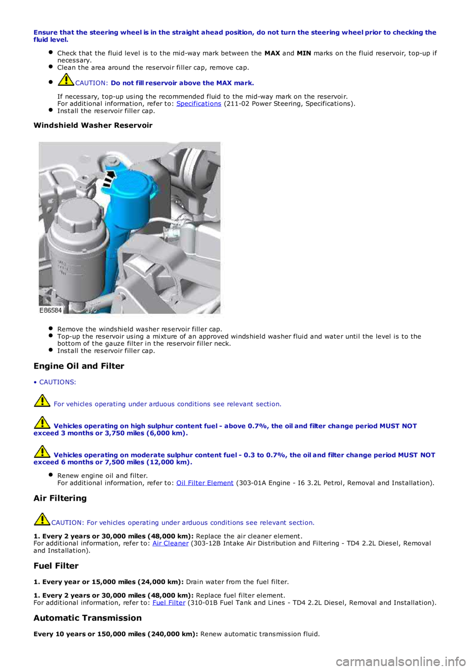
Windshield Washer Reservoir
Remove the winds hi eld was her res ervoir fill er cap.
Top-up t he res ervoir us ing a mi xt ure of an approved wi nds hiel d was her flui d and wate
r unti l the level i s t o the
bott om of t he gauze fil ter i n t he res ervoir fil ler neck. Ins t all the res ervoir fill er cap.
Engine Oil and Filter
• CAUTIO NS: For vehi cl es operati ng under arduous condi ti ons see relevant secti on.
Vehicles operating on high sulphur content fuel - above 0.7%, the oil and filter cha nge period MUST NOT
exceed 3 months or 3,750 miles (6,000 km).
Vehicles operating on moderate sulphur content fuel - 0.3 to 0.7%, the oil and filte r change period MUST NOT
exceed 6 months or 7,500 miles (12,000 km).
Renew engi ne oil and fil ter.
For addit ional informat ion, refer t o: Oil Fil ter El ement (303-01A Engine - I6 3.2L Pet rol , Removal and Ins t allat ion).
Air Filtering
CAUTION: For vehi cl es operati ng under arduous condi ti ons s ee relevant s ecti on.
1. Every 2 years or 30,000 miles (48,000 km): Replace the ai r cl eaner element .
For addit ional informat ion, refer t o: Air Cl eaner (303-12B Int ake Ai r Dis t ri but ion and Fi lt ering - TD4 2.2L Di es el, Removal
and Ins t allat ion).
Fuel Filter
1. Every year or 15,000 miles (24,000 km): Drai n water from the fuel fi lt er.
1. Every 2 years or 30,000 miles (48,000 km): Replace fuel fi lt er el ement.
For addit ional informat ion, refer t o: Fuel Fil ter (310-01B Fuel Tank and Lines - TD4 2.2L Dies el, Removal and Ins tall ati on).
Automatic Transmission
Every 10 years or 150,000 miles (240,000 km): Renew automat ic t rans mis s ion flui d.
Page 191 of 3229
For addit ional informat ion, refer t o: Specificati ons (307-01 Aut omati c Trans mis s ion/Transaxle, Speci fi cat ions ).
Manual Transmission
Every 10 years or 150,000 miles (240,000 km): Renew manual t rans mi ss ion fl ui d.
For addit ional informat ion, refer t o: Specificati ons (308-00 Manual Trans mis s ion/Transaxle and Clutch - General
Informat ion, Speci ficat ions).
Power Transfer Unit
Every 10 years or 150,000 miles (240,000 km): Renew power t rans fer unit oi l. For addi ti onal informat ion, refer to:
(308-07B Transfer Case)
Power Trans fer Uni t - TD4 2.2L Di esel , Vehi cl es W i th: M66 6-Speed Manual Trans mis s io n AW D (Removal and
Ins tal lat ion),
Power Trans fer Uni t - TD4 2.2L Di esel , Vehi cl es W i th: M66 6-Speed Manual Trans mis s io n AW D (Removal and
Ins tal lat ion).
Differential Assembly - Rear
Every 10 years or 150,000 miles (240,000 km): Renew rear different ial oil .
For addit ional informat ion, refer t o: Specificati ons (205-02 Rear Drive Axle/Different ial, Specifi cat ions ).
Suspension and Body Mountings Check for free play i n all s us pens ion and body mounti ng rubbers . Check condit ion of s uspens ion rubber boots and gait ers .
Fuel System
Check fuel sys tem pipes , hos es and unions for chafi ng, l eaks and corros ion. Electrical Harnesses
Check al l el ect ri cal harnes s es for chafing. Oil/Fluid Leaks
Check for oil/fluid leaks . Power Steering
Check power s teering rod bal l joi nt fixi ngs , gait ers and condi ti on of bal l joi nt s an d dus t covers .Check power s teering pipes , hos es and unions for chafi ng, leaks and corros ion.
Exhaust System
Check exhaust s ys tem for l eaks , securi ty and damage. Clutch
1. Check clut ch pipes and unions for chafi ng, l eaks and corrosi on.
Fault Lamp(s) If fault l amp(s ) are ill uminat ed, t est the as s oci at ed s yst em us i ng Land Rover approv ed di agnos ti c equipment and
report findi ngs . Road Test
Carry out road t est of vehicle.
For addit ional informat ion, refer t o: Road/Roller Tes ti ng (100-00 General Informati on, Des cri pt ion and Operati on).
General
Endors e Service Record. Report any unus ual features of vehi cl e condi ti on and any addi ti onal work required.
Vehicles Operating Under Arduous Conditions
Recommended s ervi ce interval s for vehicles operat ing under arduous condit ions are de t ail ed below.
Braking System CAUTION:
When vehicles are operating under arduous conditions, the following service items mu st be carried
out every 3 months or 3,750 miles (6,000 km).
Ins pect front brake pads for wear.
Page 603 of 3229
Publi s hed: 23-Aug-2011
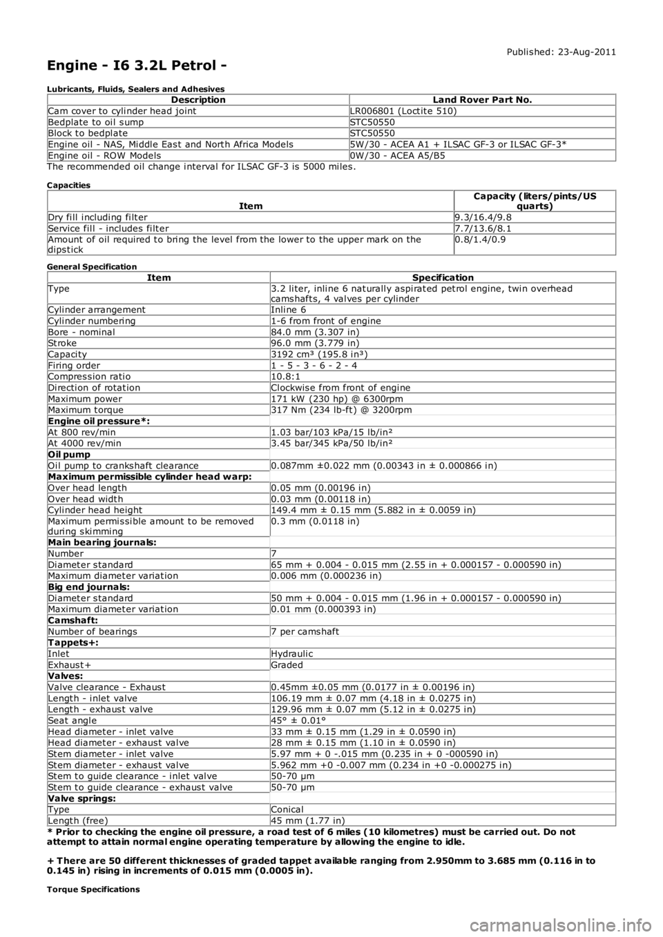
Engine - I6 3.2L Petrol -
Lubricants, Fluids, Sealers and AdhesivesDescriptionLand Rover Part No.
Cam cover to cyli nder head jointLR006801 (Loct it e 510)
Bedplate to oi l s umpSTC50550Block t o bedpl ateSTC50550
Engine oil - NAS, Mi ddl e Eas t and Nort h Africa Models5W /30 - ACEA A1 + ILSAC GF-3 or ILSAC GF-3*
Engine oil - ROW Models0W /30 - ACEA A5/B5The recommended oil change i nterval for ILSAC GF-3 is 5000 mi les .
C apacities
ItemCapacity (liters/pints/USquarts)
Dry fi ll i ncludi ng fi lt er9.3/16.4/9.8
Service fil l - includes fi lt er7.7/13.6/8.1Amount of oil required t o bri ng the level from the lower to the upper mark on thedips t ick0.8/1.4/0.9
General Specification
ItemSpecificationType3.2 li ter, inli ne 6 nat urall y aspi rat ed pet rol engine, twi n overheadcams haft s, 4 val ves per cylinderCyli nder arrangementInli ne 6
Cyli nder numberi ng1-6 from front of engine
Bore - nominal84.0 mm (3.307 in)St roke96.0 mm (3.779 in)
Capaci ty3192 cm³ (195.8 i n³)
Firing order1 - 5 - 3 - 6 - 2 - 4Compres s ion rati o10.8:1
Di recti on of rotat ionCl ockwis e from front of engi ne
Maximum power171 kW (230 hp) @ 6300rpmMaximum t orque317 Nm (234 lb-ft ) @ 3200rpm
Engine oil pressure*:
At 800 rev/min1.03 bar/103 kPa/15 lb/in²At 4000 rev/min3.45 bar/345 kPa/50 lb/in²
Oil pump
Oi l pump to cranks haft clearance0.087mm ±0.022 mm (0.00343 i n ± 0.000866 i n)Maximum permissible cylinder head w arp:
Over head length0.05 mm (0.00196 i n)
Over head widt h0.03 mm (0.00118 i n)Cyli nder head height149.4 mm ± 0.15 mm (5.882 in ± 0.0059 i n)
Maximum permi s si ble amount t o be removedduri ng s ki mmi ng0.3 mm (0.0118 in)
Main bearing journals:
Number7
Di amet er s tandard65 mm + 0.004 - 0.015 mm (2.55 in + 0.000157 - 0.000590 in)Maximum diamet er variat ion0.006 mm (0.000236 in)
Big end journals:
Di amet er s tandard50 mm + 0.004 - 0.015 mm (1.96 in + 0.000157 - 0.000590 in)Maximum diamet er variat ion0.01 mm (0.000393 i n)
Camshaft:
Number of bearings7 per cams haftT appets+:
InletHydrauli c
Exhaus t +GradedValves:
Valve clearance - Exhaus t0.45mm ±0.05 mm (0.0177 in ± 0.00196 in)
Lengt h - i nlet valve106.19 mm ± 0.07 mm (4.18 in ± 0.0275 i n)Lengt h - exhaus t valve129.96 mm ± 0.07 mm (5.12 in ± 0.0275 i n)
Seat angl e45° ± 0.01°
Head diamet er - inlet valve33 mm ± 0.15 mm (1.29 in ± 0.0590 i n)Head diamet er - exhaus t val ve28 mm ± 0.15 mm (1.10 in ± 0.0590 i n)
St em diamet er - inlet valve5.97 mm + 0 -.015 mm (0.235 in + 0 -000590 i n)
St em diamet er - exhaus t val ve5.962 mm +0 -0.007 mm (0.234 in +0 -0.000275 i n)St em t o guide clearance - i nlet val ve50-70 µm
St em t o guide clearance - exhaus t valve50-70 µm
Valve springs:TypeConical
Lengt h (free)45 mm (1.77 in)
* Prior to checking the engine oil pressure, a road test of 6 miles (10 kilometres) must be carried out. Do notattempt to attain normal engine operating temperature by allowing the engine to idle.
+ T here are 50 different thicknesses of graded tappet available ranging from 2.950mm to 3.685 mm (0.116 in to0.145 in) rising in increments of 0.015 mm (0.0005 in).
Torque Specifications
Page 647 of 3229
SymptomAction
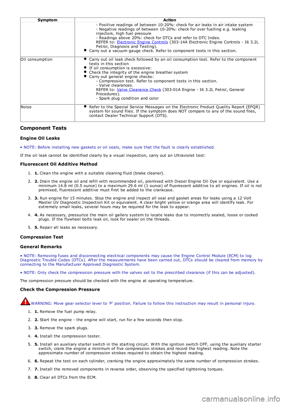
- Pos it ive readi ngs of bet ween 10-20%: check for air leaks i n air i nt ake s ys t em- Negati ve readings of between 10-20%: check for over fuell ing e.g. leaki ngi njectors , high fuel pres sure- Readings above 20%: check for DTCs and refer t o DTC Index.REFER t o: El ect ronic Engi ne Cont rol s (303-14A El ect roni c Engi ne Cont rol s - I6 3.2LPet rol, Di agnos is and Tes ti ng).Carry out a vacuum gauge check. Refer to component t es ts i n t his s ecti on.
Oi l cons umpti onCarry out oil l eak check fol lowed by an oi l cons umpt ion tes t. Refer t o t he componentt est s i n t hi s s ect ionIf oil cons umpt ion i s exces si ve:Check the integrit y of the engine breat her sys t emCarry out general engi ne checks :- Compress ion tes t. Refer t o component t es ts i n t his s ect ion.- Val ve cl earances .REFER t o: Val ve Clearance Check (303-01A Engine - I6 3.2L Pet rol , GeneralProcedures ).- Spark pl ug condi ti on and col or
Nois eRefer t o t he Speci al Servi ce Mess ages on t he Electroni c Product Q ual it y Report (EPQR)s ys tem for s ound fi les . If t he s ympt om does NOT compare t o any of the s ound files ,contact Deal er Technical Support (DTS).
Component Tests
Engine Oil Leaks
• NOTE: Before ins t al li ng new gasket s or oil s eal s, make sure t hat t he faul t is cl early es t abl is hed.
If the oi l l eak cannot be ident ifi ed clearl y by a vi sual ins pect ion, carry out an Ult raviolet t est :
Fluorescent Oil Additive Method
1. Clean t he engi ne wit h a sui table cl eani ng fl uid (brake cleaner).1.
2. Drai n the engi ne oil and refil l wit h recommended oil , premixed wi th Dies el Engine Oil Dye or equi val ent . Us e aminimum 14.8 ml (0.5 ounce) t o a maxi mum 29.6 ml (1 ounce) of fl uores cent addit ive to all engines. If oil i s notpremixed, fl uorescent addi ti ve mus t fi rs t be added to the crankcas e.
2.
3. Run engi ne for 15 minutes . Stop the engine and i nspect all s eal and gas ket areas for leaks us ing a 12 Vol tMas t er UV Diagnost ic Ins pect ion Ki t or equivalent . A clear bri ght yell ow or orange area wil l i dent ify l eak. Forext remely smal l leaks, s everal hours may be required for t he leak t o appear.
3.
4. As neces s ary, pres surize t he main oil gallery s yst em t o l ocat e leaks due t o incorrect ly sealed, loos e or cockedpl ugs . If the flywheel bol ts l eak oil, l ook for s ealer on t he threads .4.
5. Repai r al l leaks as neces s ary.5.
Compression Test
General Remarks
• NOTE: Removing fuses and di sconnect ing elect rical components may caus e t he Engine Control Modul e (ECM) t o l ogDiagnost ic Troubl e Codes (DTCs ). Aft er t he meas urements have been carried out , DTCs should be cl eared from memory byconnecti ng to the Manufact urer Approved Diagnos t ic Sys tem.
• NOTE: Only check the compress ion pres sure wit h t he valves s et to the pres cri bed clearance (i f thi s can be adjus ted).
The compres si on pres s ure s hould be checked wi th the engine at operat ing temperat ure.
Check the Comp ression Pressure
W ARNING: Move gear s elector lever to 'P' pos i ti on. Fail ure t o follow thi s ins t ructi on may res ult i n pers onal injury.
1. Remove the fuel pump rel ay.1.
2. Start the engine - the engine wi ll s t art, run for a few seconds then s t op.2.
3. Remove the s park pl ugs.3.
4. Ins t al l the compres s ion t es ter.4.
5. Ins t al l an auxi li ary s tarter s wit ch in the st art ing circui t. W it h t he ignit ion swi tch O FF, us ing t he auxi li ary s t arters wi tch, crank the engine a mi ni mum of five compres s ion st rokes and record the hi ghest reading. Not e theapproximat e number of compress i on s trokes requi red t o obt ai n t he highest readi ng.
5.
6. Repeat t he tes t on each cyl inder, cranking t he engine approximat ely t he s ame number of compress i on st rokes .6.
7. Ins t al l the removed components in reverse order, obs erving t he s peci fi ed ti ght ening t orques.7.
8. Clear all DTCs from the ECM.8.