tire pressure LAND ROVER FRELANDER 2 2006 Repair Manual
[x] Cancel search | Manufacturer: LAND ROVER, Model Year: 2006, Model line: FRELANDER 2, Model: LAND ROVER FRELANDER 2 2006Pages: 3229, PDF Size: 78.5 MB
Page 32 of 3229

(1) Ride height is measured vertically from wheel center to underside of wheelarch. All figures are with vehicle at'Show room' height - full fluids, full tank of fuel, no occupants/luggage, tires inflated to normal pressures.
(2) 5 seconds maximum duration.
Page 156 of 3229
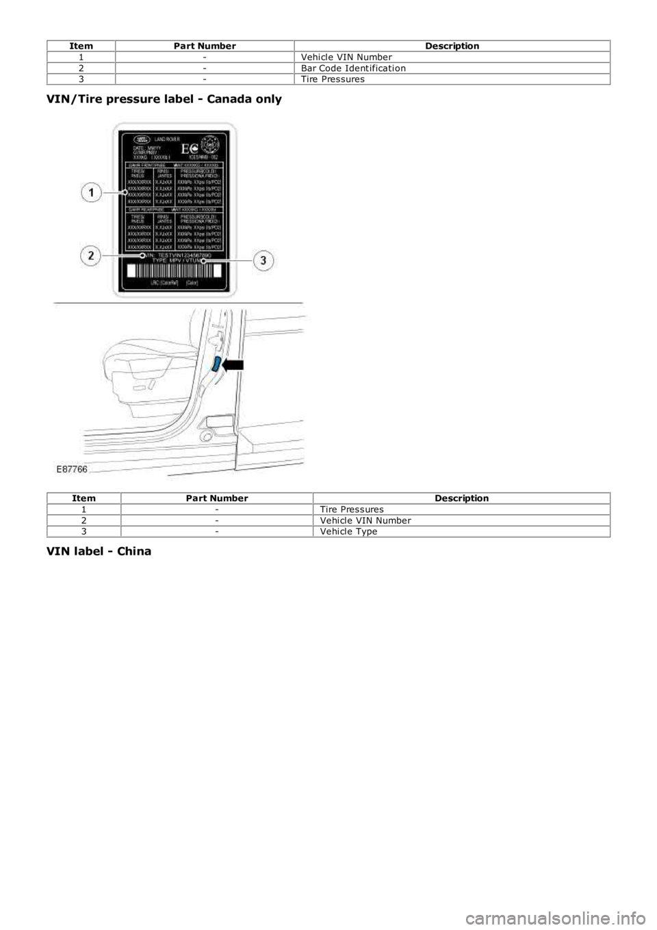
ItemPart NumberDescription
1-Vehi cl e VIN Number
2-Bar Code Ident ificati on3-Tire Pres sures
VIN/Tire pressure label - Canada only
ItemPart NumberDescription
1-Tire Pres s ures
2-Vehi cl e VIN Number3-Vehi cl e Type
VIN label - China
Page 272 of 3229
Publi s hed: 11-May-2011
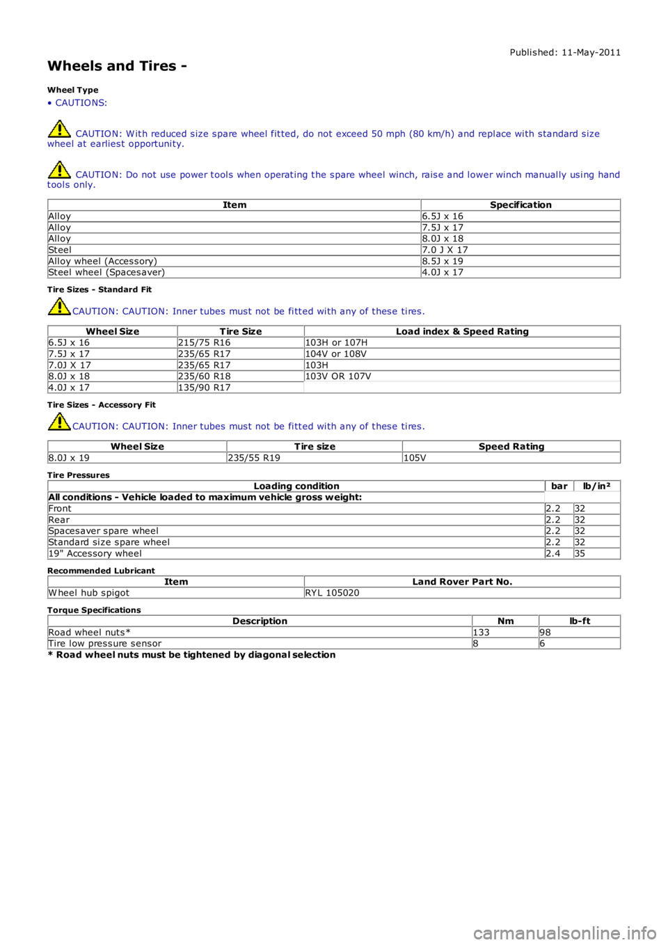
Wheels and Tires -
Wheel Type
• CAUTIO NS:
CAUTIO N: W it h reduced s ize s pare wheel fit ted, do not exceed 50 mph (80 km/h) and repl ace wi th s tandard s izewheel at earlies t opportuni ty.
CAUTIO N: Do not use power t ool s when operat ing t he s pare wheel winch, rais e and l ower winch manual ly us i ng handt ool s only.
ItemSpecification
All oy6.5J x 16
All oy7.5J x 17All oy8.0J x 18
St eel7.0 J X 17
All oy wheel (Acces s ory)8.5J x 19St eel wheel (Spaces aver)4.0J x 17
Tire Sizes - Standard Fit
CAUTION: CAUTION: Inner tubes mus t not be fi tt ed wi th any of t hes e ti res .
Wheel SizeT ire SizeLoad index & Speed Rating6.5J x 16215/75 R16103H or 107H
7.5J x 17235/65 R17104V or 108V
7.0J X 17235/65 R17103H8.0J x 18235/60 R18103V OR 107V
4.0J x 17135/90 R17
Tire Sizes - Accessory Fit
CAUTION: CAUTION: Inner tubes mus t not be fi tt ed wi th any of t hes e ti res .
Wheel SizeT ire sizeSpeed Rating
8.0J x 19235/55 R19105V
Tire Pressures
Loading conditionbarlb/in²All conditions - Vehicle loaded to maximum vehicle gross w eight:
Front2.232
Rear2.232Spaces aver s pare wheel2.232
St andard si ze s pare wheel2.232
19" Acces sory wheel2.435
Recommended Lubricant
ItemLand Rover Part No.W heel hub s pigotRY L 105020
Torque Specifications
DescriptionNmlb-ft
Road wheel nut s *13398Tire l ow pres s ure s ens or86
* Road wheel nuts must be tightened by diagonal selection
Page 274 of 3229
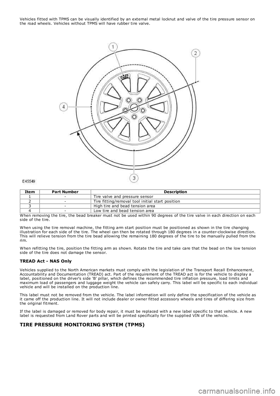
Vehicles fit ted wi th TPMS can be vis ual ly ident ified by an ext ernal met al l ocknut and val ve of the t ire pres s ure sens or ont he road wheels . Vehicles wi thout TPMS wil l have rubber t ire valve.
ItemPart NumberDescription
1-Ti re val ve and pres sure s ens or
2-Ti re fit t ing/removal t ool i nit ial s tart pos it ion3-Hi gh t ire and bead tens ion area
4-Low ti re and bead t ensi on area
W hen removing t he ti re, t he bead breaker mus t not be us ed wit hin 90 degrees of the tire valve i n each di recti on on eachs ide of t he ti re.
W hen us ing the t ire removal machine, the fit t ing arm s t art posi ti on mus t be posi ti oned as s hown in t he t ire changingil lus trati on for each s ide of t he ti re. The wheel can t hen be rotat ed through 180 degrees i n a counter-clockwis e direct ion.This wi ll rel ieve t ens i on from t he t ire bead allowi ng t he remai ni ng 180 degrees of the t ire t o be manuall y pull ed from t heri m.
W hen refi tt ing t he t ire, pos it ion t he fit ti ng arm as s hown. Rot ate t he t ire and t ake care that t he bead on t he low tens ions ide of t he ti re does not damage t he s ens or.
TREAD Act - NAS Only
Vehicles s uppl ied t o t he Nort h American market s mus t comply wi th the l egi s lati on of the Transport Recall Enhancement,Accountabil it y and Document ati on (TREAD) act. Part of t he requirement of the TREAD act is for the vehicl e to dis play alabel, pos it ioned on t he dri ver's s ide 'B' pill ar, which defines t he recommended ti re infl ati on pres sure, load li mit s andmaximum load of pas sengers and luggage wei ght the vehicle can s afel y carry. This label wi ll be s peci fi c t o each individualvehi cl e and wi ll be i ns t alled on the product ion l ine.
This l abel mus t not be removed from the vehicl e. The l abel i nformat ion will only define t he s peci fi cat ion of t he vehi cl e asit came off the product ion l ine. It will not include dealer or owner fit t ed acces sory wheel s and t ires of di fferi ng si ze fromt he origi nal fit ment.
If the l abel i s damaged or removed for body repair, it mus t be repl aced wit h a new label s peci fi c t o that vehicle. A newlabel is reques t ed from Land Rover parts and will be print ed s pecificall y for t he s uppl ied VIN of t he vehi cl e.
TIRE PRESSURE MONITORING SYSTEM (TPMS)
Page 277 of 3229
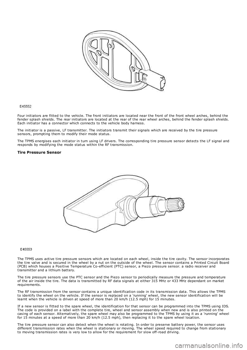
Four i nit iators are fi tt ed t o the vehicl e. The front i ni ti ators are l ocat ed near t he front of the front wheel arches , behind t hefender s pl ash shi elds . The rear init iat ors are located at t he rear of t he rear wheel arches , behind t he fender spl ash shi el ds.Each init iat or has a connect or which connects to the vehicle body harnes s .
The ini ti at or is a pass ive, LF t rans mit ter. The init iat ors t rans mi t their s ignals which are recei ved by the ti re press ures ens ors , prompt ing them to modi fy their mode st atus .
The TPMS energis es each init iat or in t urn usi ng LF dri vers. The corres ponding t ire pres s ure sens or det ect s t he LF s ignal andres ponds by modifyi ng the mode s tat us wit hin t he RF t rans mis s ion.
Tire Pressure Sensor
The TPMS us es act ive t ire pres s ure s ens ors whi ch are l ocat ed on each wheel , ins ide the ti re cavit y. The sens or incorporat est he ti re val ve and is s ecured in the wheel by a nut on t he outs i de of the wheel. The s ensor contains a Pri nt ed Ci rcuit Board(PCB) whi ch hous es a Pos it ive Temperat ure Co-efficient (PTC) s ens or, a Piezo pres s ure s ens or. a radi o receiver andt ransmit ter and a l it hium bat t ery.
The t ire pres sure s ensors use the PTC sens or and the Pi ezo sens or to periodically measure t he pres sure and t emperatureof the ai r ins ide t he t ire. The dat a is trans mi tt ed by RF dat a s ignals at ei ther 315 MHz or 433 MHz dependant on marketrequirements .
The RF t rans mis s ion from t he sens or cont ai ns a unique i dent ificati on code in i ts trans mi ss i on dat a. This all ows t he TPMSt o identi fy the wheel on t he vehi cl e. If t he s ens or is replaced on a 'running' wheel, t he new s ens or i dent ificati on wil l belearnt when the vehicle is driven at s peed of more t han 20 km/h (12.5 mph) for 15 minutes .
If a new s ensor i s fi tt ed t o t he spare wheel, t he identi fi cat ion for that s ens or can be programmed int o t he TPMS usi ng IDS.The code is provi ded on a l abel wit h t he complet e ti re, wheel and sens or ass embly when new and is al s o pri nted on t hecas i ng of each s ensor. Alt ernati vel y, t he s pare wheel may al so be programmed to the TPMS by us i ng it as a 'running' wheelfor 15 minutes at a speed of more t han 20 km/h (12.5 mph), t hen replacing it t o t he spare wheel l ocat ion.
The t ire pres sure s ensor can als o det ect when t he wheel i s rot ati ng. In order t o preserve bat t ery power, t he s ens or us esdifferent t rans mis s ion rates when the wheel is st ati onary or moving. The wheel s peed required to change from st ati onaryt o moving t rans mis s ion rates is very low t o al low for the requi rement for sl ow off-road dri ving.
Page 278 of 3229
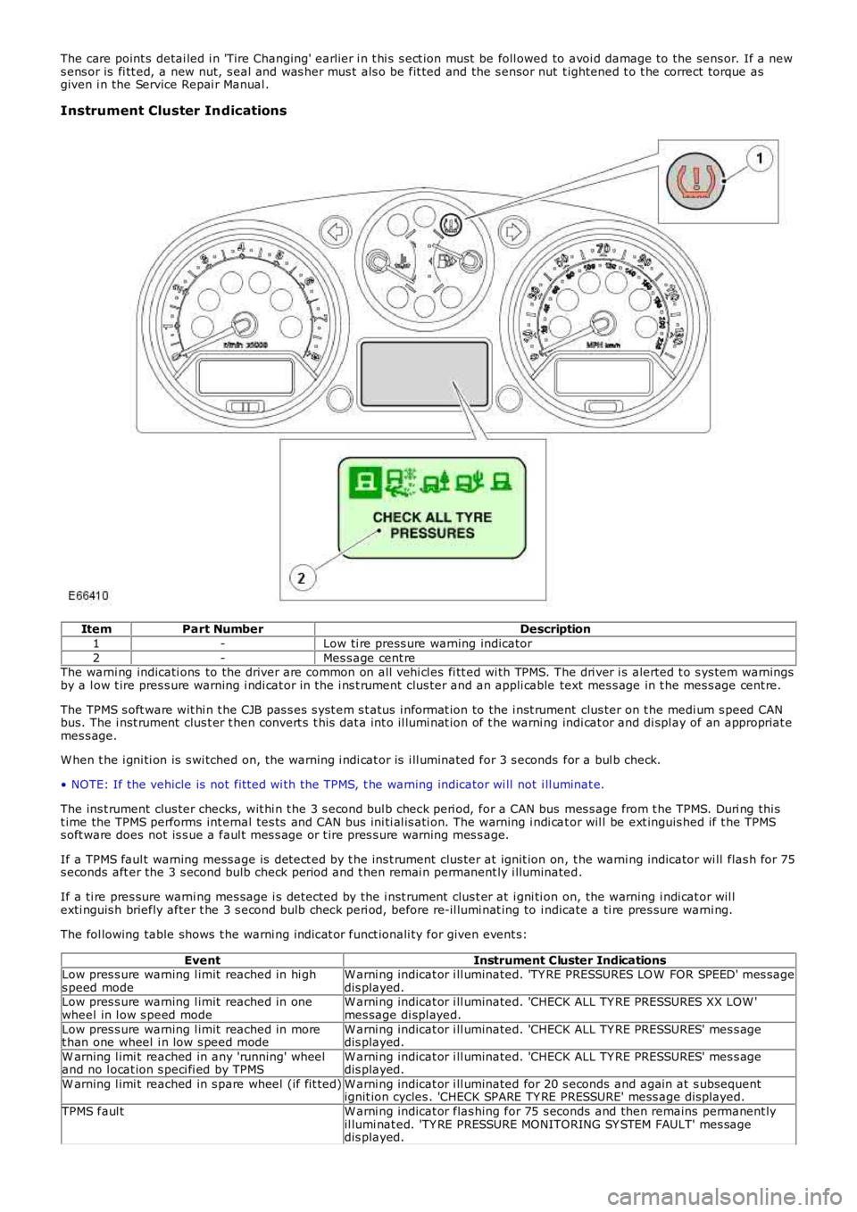
The care point s detai led i n 'Tire Changing' earlier i n t hi s s ect ion must be foll owed to avoi d damage to the sens or. If a news ens or is fi tt ed, a new nut, s eal and was her mus t als o be fit ted and the s ensor nut t ightened t o t he correct torque asgiven i n the Service Repai r Manual .
Instrument Cluster Indications
ItemPart NumberDescription
1-Low ti re press ure warning indicator
2-Mes s age cent reThe warni ng indicati ons to the driver are common on all vehi cl es fi tt ed wi th TPMS. The dri ver i s alerted t o s ys tem warningsby a l ow t ire pres s ure warning i ndi cat or in t he i ns t rument clus ter and an appli cable text mes s age in t he mes s age cent re.
The TPMS s oft ware wit hi n t he CJB pas s es s yst em s t atus i nformat ion to the i nst rument clus ter on t he medi um s peed CANbus. The i nst rument clus t er t hen convert s t his dat a int o il lumi nat ion of t he warni ng indi cat or and di spl ay of an appropriat emes s age.
W hen t he i gni ti on is s wi tched on, the warning i ndi cat or is i ll uminated for 3 s econds for a bul b check.
• NOTE: If the vehicle is not fit ted wi th the TPMS, t he warning indicator wi ll not ill uminat e.
The ins t rument clus ter checks, wit hi n t he 3 s econd bul b check peri od, for a CAN bus mes s age from t he TPMS. Duri ng thi st ime the TPMS performs int ernal tes ts and CAN bus ini ti al is ati on. The warning i ndi cat or wil l be ext inguis hed if t he TPMSs oft ware does not is s ue a faul t mes s age or t ire pres s ure warning mes s age.
If a TPMS faul t warning mess age is det ect ed by t he ins t rument clus ter at ignit ion on, t he warni ng indicator wi ll flas h for 75s econds aft er the 3 s econd bulb check period and t hen remai n permanent ly i lluminated.
If a ti re pres sure warni ng mes sage i s detected by the i nst rument clus t er at i gni ti on on, the warning i ndi cat or wil lexti nguis h briefly after t he 3 s econd bulb check peri od, before re-il lumi nat ing to indicate a ti re pres sure warni ng.
The fol lowing table shows t he warni ng indicat or funct ionali ty for given event s:
EventInstrument Cluster IndicationsLow pres s ure warning l imit reached in hi ghs peed modeW arni ng indicat or i ll uminated. 'TY RE PRESSURES LO W FOR SPEED' mes sagedis played.Low pres s ure warning l imit reached in onewheel in l ow s peed modeW arni ng indicat or i ll uminated. 'CHECK ALL TY RE PRESSURES XX LOW 'mes sage di spl ayed.
Low pres s ure warning l imit reached in moret han one wheel i n low s peed modeW arni ng indicat or i ll uminated. 'CHECK ALL TY RE PRESSURES' mes s agedis played.
W arning l imi t reached in any 'running' wheeland no l ocat ion s peci fi ed by TPMSW arni ng indicat or i ll uminated. 'CHECK ALL TY RE PRESSURES' mes s agedis played.
W arning l imi t reached in s pare wheel (if fit ted)W arni ng indicat or i ll uminated for 20 s econds and again at s ubsequentignit ion cycles . 'CHECK SPARE TY RE PRESSURE' mess age dis played.
TPMS faul tW arni ng indicat or flas hing for 75 s econds and then remains permanent lyil lumi nat ed. 'TY RE PRESSURE MONITORING SY STEM FAULT' mes sagedis played.
Page 284 of 3229
Publi s hed: 11-May-2011
Wheels and Tires - Tire Low Pressure Sensor
Removal and Inst all ati on
Removal
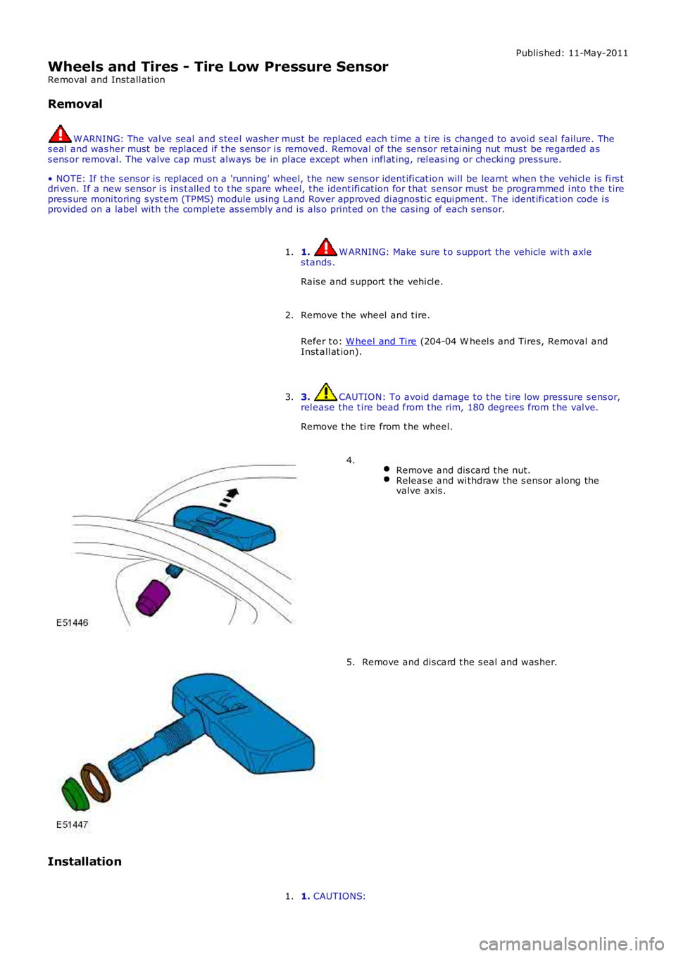
W ARNING: The val ve seal and s teel was her mus t be replaced each t ime a t ire is changed to avoi d s eal failure. Thes eal and was her must be replaced if t he s ensor i s removed. Removal of the sens or retai ning nut mus t be regarded ass ens or removal. The valve cap mus t always be in pl ace except when i nfl at ing, rel easing or checki ng pres s ure.
• NOTE: If the s ens or i s repl aced on a 'runni ng' wheel, t he new s ens or ident ifi cat ion will be learnt when t he vehi cl e i s fi rs tdri ven. If a new s ensor i s ins t al led t o t he s pare wheel, t he ident ifi cat ion for that s ensor mus t be programmed i nto t he t irepres s ure moni toring s yst em (TPMS) module us ing Land Rover approved di agnos ti c equi pment . The ident ifi cat ion code i sprovided on a label wit h t he compl ete as s embly and i s als o print ed on t he cas ing of each s ens or.
1. W ARNING: Make sure t o s upport the vehicle wit h axles tands .
Rais e and s upport t he vehi cl e.
1.
Remove t he wheel and t ire.
Refer t o: W heel and Ti re (204-04 W heel s and Tires, Removal andInst all at ion).
2.
3. CAUTION: To avoid damage t o t he t ire low pres sure s ens or,rel ease the t ire bead from the rim, 180 degrees from t he val ve.
Remove t he ti re from t he wheel.
3.
Remove and dis card t he nut.Releas e and wi thdraw the s ens or al ong thevalve axis .
4.
Remove and dis card t he s eal and was her.5.
Installation
1. CAUTIONS:1.
Page 286 of 3229
Publi s hed: 11-May-2011
Wheels and Tires - Tire Pressure Monitoring System (TPMS) Receiver
Removal and Inst all ati on
Removal
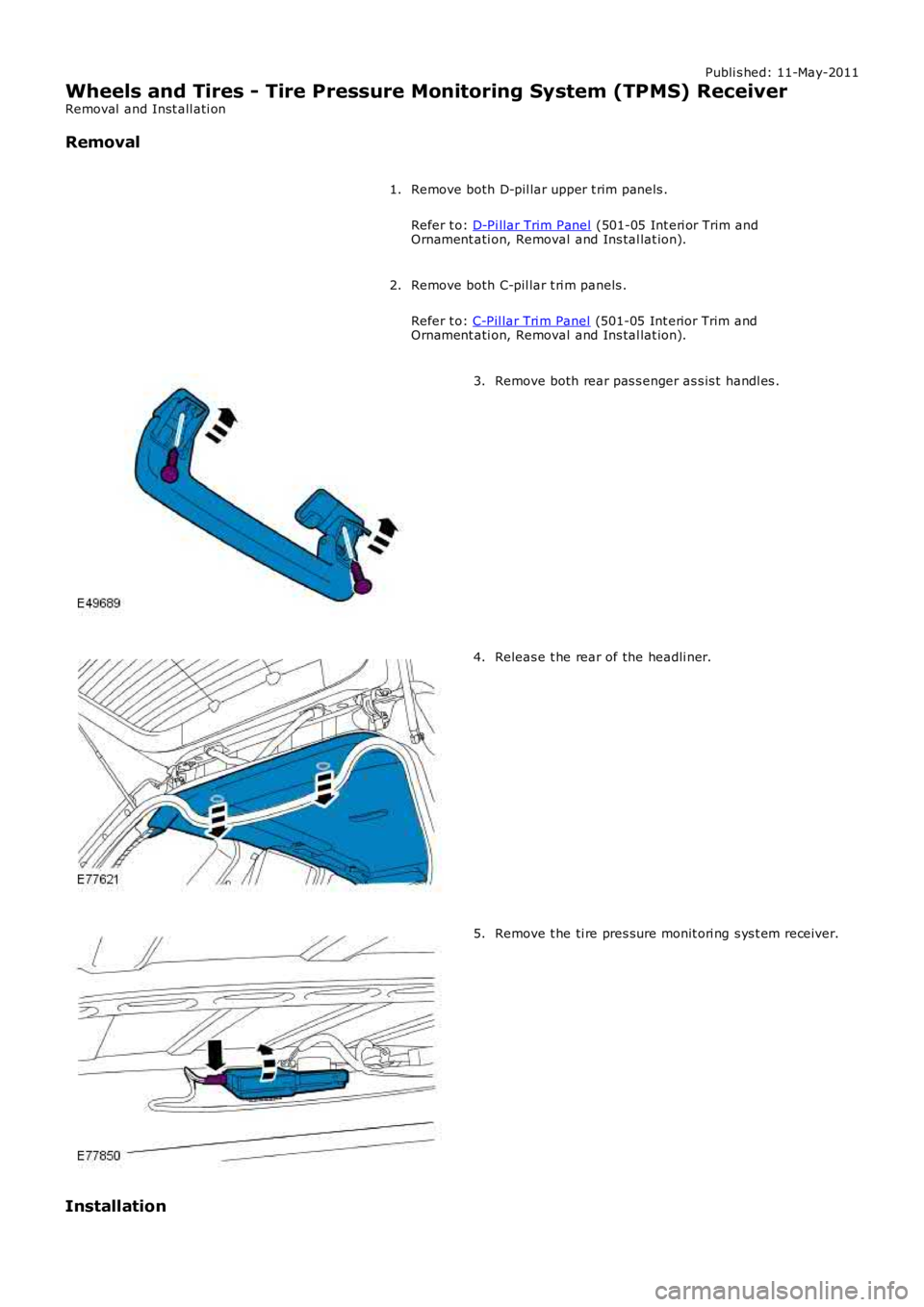
Remove both D-pil lar upper t rim panels .
Refer t o: D-Pi llar Trim Panel (501-05 Int eri or Trim andOrnament ati on, Removal and Ins tal lat ion).
1.
Remove both C-pil lar t ri m panels .
Refer t o: C-Pil lar Tri m Panel (501-05 Int erior Trim andOrnament ati on, Removal and Ins tal lat ion).
2.
Remove both rear pas s enger as s is t handl es .3.
Releas e t he rear of the headli ner.4.
Remove t he ti re pres sure monit ori ng s ys t em receiver.5.
Installation
Page 288 of 3229
Publi s hed: 11-May-2011
Wheels and Tires - Tire Pressure Monitoring System (TPMS) Front Antenna
Removal and Inst all ati on
Removal
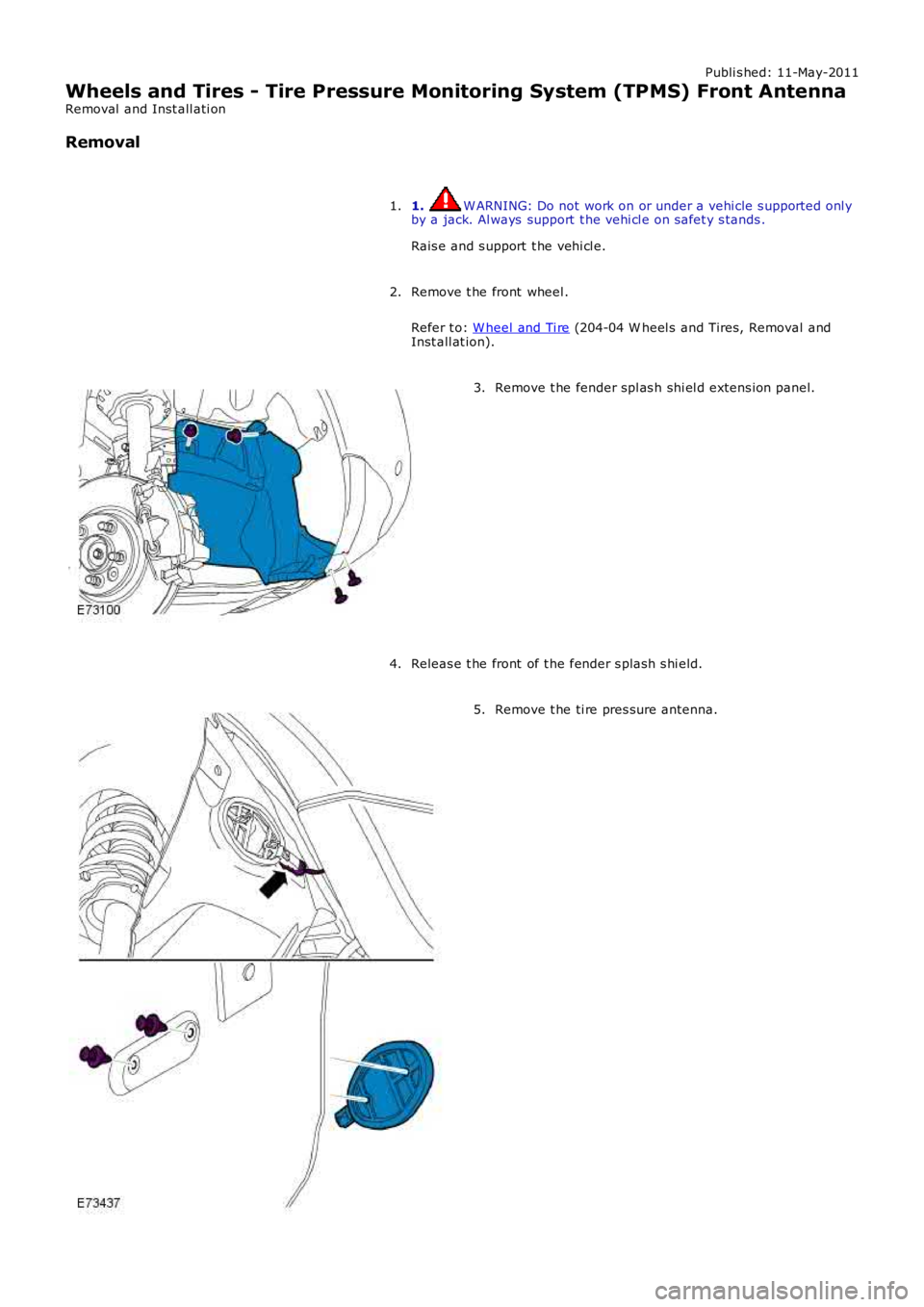
1. W ARNING: Do not work on or under a vehi cle s upported onl yby a jack. Al ways support t he vehi cl e on s afet y s tands .
Rais e and s upport t he vehi cl e.
1.
Remove t he front wheel .
Refer t o: W heel and Ti re (204-04 W heel s and Tires, Removal andInst all at ion).
2.
Remove t he fender spl as h shi el d extens ion panel.3.
Releas e t he front of t he fender s plas h s hi eld.4.
Remove t he ti re pres sure antenna.5.
Page 290 of 3229
Publi s hed: 11-May-2011
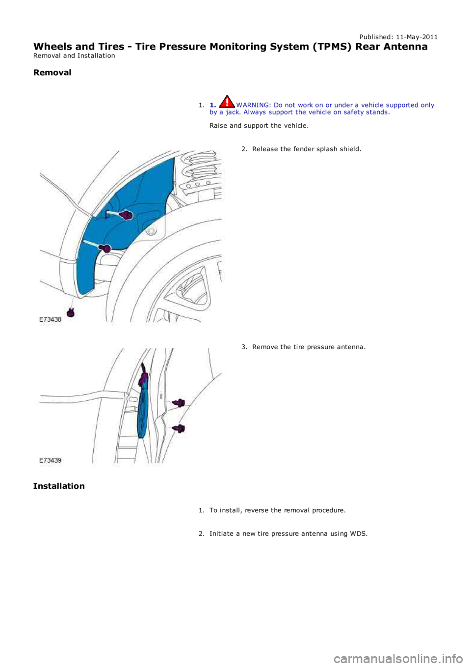
Wheels and Tires - Tire Pressure Monitoring System (TPMS) Rear Antenna
Removal and Inst all ati on
Removal
1. W ARNING: Do not work on or under a vehi cle s upported onl yby a jack. Al ways support t he vehi cl e on s afet y s tands .
Rais e and s upport t he vehi cl e.
1.
Releas e t he fender spl as h shi el d.2.
Remove t he ti re pres sure antenna.3.
Installation
To i nst all , revers e t he removal procedure.1.
Init iate a new t ire pres s ure ant enna us i ng W DS.2.