stop start Lexus ES350 2019 / LEXUS 2019 ES350 (OM06130U) Owner's Guide
[x] Cancel search | Manufacturer: LEXUS, Model Year: 2019, Model line: ES350, Model: Lexus ES350 2019Pages: 444, PDF Size: 14.22 MB
Page 236 of 444
2364-5. Using the driving support systems
■ABS (Anti-lock Brake System)
Helps to prevent wheel lock when the
brakes are applied suddenly, or if the
brakes are applied while driving on a
slippery road surface
■Brake assist
Generates an increased level of brak-
ing force after the brake pedal is
depressed when the system detects a
panic stop situation
■VSC (Vehicle Stability Control)
Helps the driver to control skidding
when swerving sudden ly or turning on
slippery road surfaces
■Enhanced VSC (Enhanced Vehi-
cle Stability Control)
Provides cooperative control of the
ABS, TRAC, VSC and EPS.
Helps to maintain directional stability
when swerving on slippery road sur-
faces by controlling steering perfor-
mance.
■Secondary Collision Brake (SCB)
When the airbag sensor detects a colli-
sion, the brakes and brake lights are
automatically controlled to reduce the
vehicle speed and that helps reduce
the possibility of further damage due to
a secondary collision
■TRAC (Traction Control)
Helps to maintain drive power and pre-
vent the drive wheels from spinning
when starting the vehicle or accelerat-
ing on slippery roads
■Active Cornering Assist (ACA)
Helps to prevent the vehicle from drift-
ing to the outer side by performing
inner wheel brake control when
attempting to acce lerate during cor-
nering
■Hill-start assist control
Helps to reduce the backward move-
ment of the vehicle when starting on an
uphill
■EPS (Electric Power Steering)
Employs an electric motor to reduce
the amount of effort needed to turn the
steering wheel
■AVS (Adaptive Variable Suspen-
sion System) (if equipped)
By independently controlling the
damping force of th e shock absorbers
for each of the 4 wheels according to
the road and driving conditions, this
system helps riding comfort with supe-
rior vehicle stability, and helps good
vehicle posture.
Also, the damping force changes
depending on the selected driving
Driving assist systems
To keep driving safety and perfor-
mance, the following systems oper-
ate automatically in response to
various driving situations. Be aware,
however, that these systems are
supplementary and should not be
relied upon too heavily when oper-
ating the vehicle.
Summary of the driving assist
systems
Page 237 of 444
2374-5. Using the driving support systems
4
Driving
mode. (P.202)
■When the TRAC/VSC systems are
operating
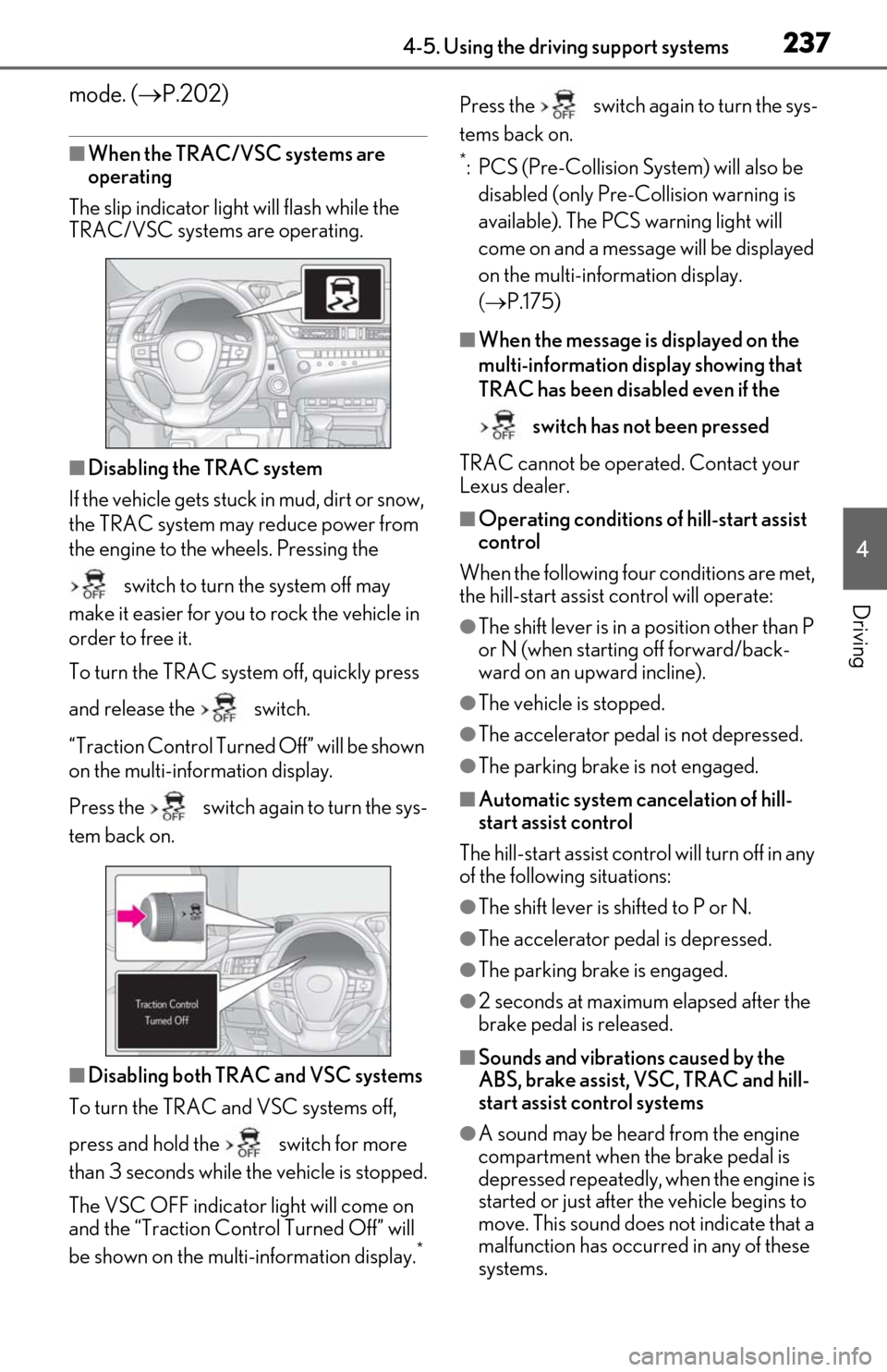
The slip indicator light will flash while the
TRAC/VSC systems are operating.
■Disabling the TRAC system
If the vehicle gets stuck in mud, dirt or snow,
the TRAC system may reduce power from
the engine to the wheels. Pressing the
switch to turn the system off may
make it easier for you to rock the vehicle in
order to free it.
To turn the TRAC system off, quickly press
and release the switch.
“Traction Control Turned Off” will be shown
on the multi-information display.
Press the switch again to turn the sys-
tem back on.
■Disabling both TRAC and VSC systems
To turn the TRAC and VSC systems off,
press and hold the switch for more
than 3 seconds while the vehicle is stopped.
The VSC OFF indicator light will come on
and the “Traction Cont rol Turned Off” will
be shown on the multi-information display.
*
Press the switch again to turn the sys-
tems back on.
*: PCS (Pre-Collision System) will also be disabled (only Pre-Collision warning is
available). The PCS warning light will
come on and a message will be displayed
on the multi-information display.
( P.175)
■When the message is displayed on the
multi-information display showing that
TRAC has been disabled even if the
switch has not been pressed
TRAC cannot be operated. Contact your
Lexus dealer.
■Operating conditions of hill-start assist
control
When the following four conditions are met,
the hill-start assist control will operate:
●The shift lever is in a position other than P
or N (when starting off forward/back-
ward on an up ward incline).
●The vehicle is stopped.
●The accelerator pedal is not depressed.
●The parking brake is not engaged.
■Automatic system cancelation of hill-
start assist control
The hill-start assist control will turn off in any
of the following situations:
●The shift lever is shifted to P or N.
●The accelerator pedal is depressed.
●The parking brake is engaged.
●2 seconds at maximum elapsed after the
brake pedal is released.
■Sounds and vibrations caused by the
ABS, brake assist, VSC, TRAC and hill-
start assist control systems
●A sound may be heard from the engine
compartment when the brake pedal is
depressed repeatedly, when the engine is
started or just after the vehicle begins to
move. This sound does not indicate that a
malfunction has occurred in any of these
systems.
Page 239 of 444
2394-5. Using the driving support systems
4
Driving
WARNING
●When driving over bumps in the road
●When driving over roads with potholes
or uneven surfaces
■TRAC/VSC may not operate effec-
tively when
Directional control and power may not
be achievable while driving on slippery
road surfaces, even if the TRAC/VSC
system is operating.
Drive the vehicle carefully in conditions
where stability and power may be lost.
■Active Cornering Assist does not
operate effectively when
●Do not rely solely upon Active Cor-
nering Assist. Active Cornering Assist
may not operate effectively when
accelerating down slopes or driving on
slippery road surfaces.
●When Active Cornering Assist fre-
quently operates, Active Cornering
Assist may temporarily stop operating
to ensure proper operation of the
brakes, TRAC, VSC.
■Hill- start assist control does not
operate effectively when
●Do not overly rely on hill-start assist
control. Hill-start assist control may
not operate effectively on steep
inclines and roads covered with ice.
●Unlike the parking brake, hill-start
assist control is not intended to hold
the vehicle stationary for an extended
period of time. Do not attempt to use
hill-start assist control to hold the vehi-
cle on an incline, as doing so may lead
to an accident.
■When the TRAC/VSC is activated
The slip indicator light flashes. Always
drive carefully. Re ckless driving may
cause an accident. Exercise particular
care when the indicator light flashes.
■When the TRAC/VSC systems are
turned off
Be especially careful and drive at a speed
appropriate to the road conditions. As
these are the systems to help ensure
vehicle stability and driving force, do not
turn the TRAC/VSC systems off unless
necessary.
■Secondary Collision Brake
Do not overly rely on the Secondary Col-
lision Brake. This system is designed to
help reduce the possibility of further
damage due to a secondary collision,
however, that effect changes according
to various conditions. Overly relying on
the system may result in death or serious
injury.
■Replacing tires
Make sure that all ti res are of the speci-
fied size, brand, tread pattern and total
load capacity. In addition, make sure that
the tires are inflated to the recom-
mended tire inflation pressure level.
The ABS, TRAC and VSC systems will
not function correctly if different tires are
installed on the vehicle.
Contact your Lexus dealer for further
information when replacing tires or
wheels.
■Handling of tires and the suspension
Using tires with any kind of problem or
modifying the suspensi on will affect the
driving assist systems, and may cause a
system to malfunction.
Page 270 of 444
2705-6. Using the other interior features
■The power outlet can be used when
The engine switch is in ACCESSORY or
IGNITION ON mode.
■When stopping the engine
Disconnect electrical devices such as
mobile battery packs.
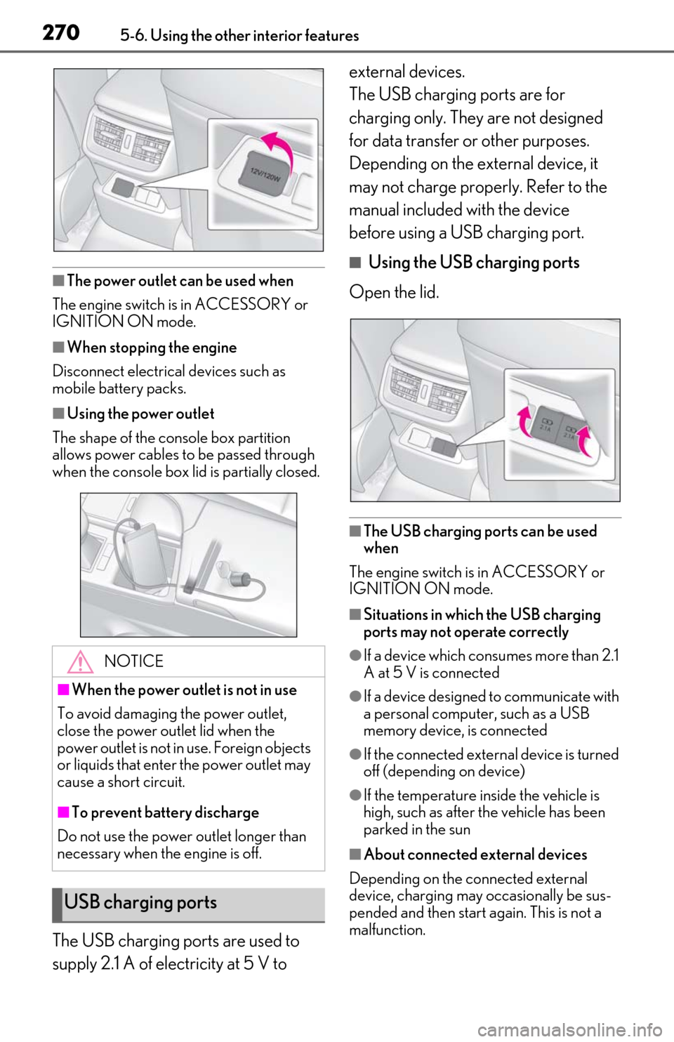
■Using the power outlet
The shape of the console box partition
allows power cables to be passed through
when the console box lid is partially closed.
The USB charging ports are used to
supply 2.1 A of electricity at 5 V to external devices.
The USB charging ports are for
charging only. They are not designed
for data transfer or other purposes.
Depending on the external device, it
may not charge properly. Refer to the
manual included with the device
before using a USB charging port.
■Using the USB charging ports
Open the lid.
■The USB charging ports can be used
when
The engine switch is in ACCESSORY or
IGNITION ON mode.
■Situations in whic h the USB charging
ports may not operate correctly
●If a device which consumes more than 2.1
A at 5 V is connected
●If a device designed to communicate with
a personal computer, such as a USB
memory device, is connected
●If the connected external device is turned
off (depending on device)
●If the temperature inside the vehicle is
high, such as after the vehicle has been
parked in the sun
■About connected external devices
Depending on the connected external
device, charging may occasionally be sus-
pended and then start again. This is not a
malfunction.
NOTICE
■When the power outlet is not in use
To avoid damaging the power outlet,
close the power outlet lid when the
power outlet is not in use. Foreign objects
or liquids that enter the power outlet may
cause a short circuit.
■To prevent battery discharge
Do not use the power outlet longer than
necessary when the engine is off.
USB charging ports
Page 272 of 444
2725-6. Using the other interior features
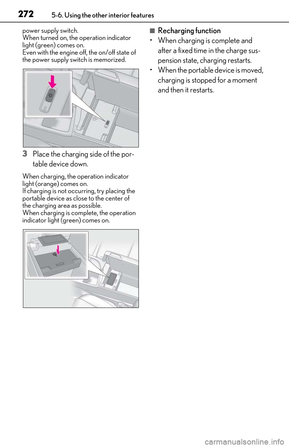
power supply switch.
When turned on, the operation indicator
light (green) comes on.
Even with the engine off, the on/off state of
the power supply switch is memorized.
3Place the charging side of the por-
table device down.
When charging, the operation indicator
light (orange) comes on.
If charging is not occurring, try placing the
portable device as close to the center of
the charging area as possible.
When charging is complete, the operation
indicator light (green) comes on.
■Recharging function
• When charging is complete and
after a fixed time in the charge sus-
pension state, ch arging restarts.
• When the portable device is moved, charging is stopped for a moment
and then it restarts.
Page 273 of 444
2735-6. Using the other interior features
5
Interior features
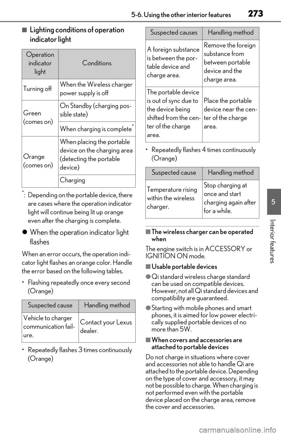
■Lighting conditions of operation
indicator light
*: Depending on the portable device, there are cases where the operation indicator
light will continue being lit up orange
even after the char ging is complete.
When the operation indicator light
flashes
When an error occurs , the operation indi-
cator light flashes an orange color. Handle
the error based on the following tables.
• Flashing repeatedly once every second (Orange)
• Repeatedly flashes 3 times continuously (Orange) • Repeatedly flashes 4 times continuously
(Orange)
■The wireless charger can be operated
when
The engine switch is in ACCESSORY or
IGNITION ON mode.
■Usable portable devices
●Qi standard wireless charge standard
can be used on compatible devices.
However, not all Qi standard devices and
compatibility ar e guaranteed.
●Starting with mobile phones and smart
phones, it is aimed for low power electri-
cally supplied portable devices of no
more than 5W.
■When covers and accessories are
attached to portable devices
Do not charge in situations where cover
and accessories not able to handle Qi are
attached to the portable device. Depending
on the type of cover and accessory, it may
not be possible to charge. When charging is
not performed even with the portable
device placed on the charge area, remove
the cover and accessories.
Operation indicator light
Conditions
Turning offWhen the Wireless charger
power supply is off
Green
(comes on)
On Standby (charging pos-
sible state)
When charging is complete*
Orange
(comes on)
When placing the portable
device on the charging area
(detecting the portable
device)
Charging
Suspected causeHandling method
Vehicle to charger
communication fail-
ure.Contact your Lexus
dealer.
Suspected causesHandling method
A foreign substance
is between the por-
table device and
charge area.Remove the foreign
substance from
between portable
device and the
charge area.
The portable device
is out of sync due to
the device being
shifted from the cen-
ter of the charge
area.
Place the portable
device near the cen-
ter of the charge
area.
Suspected causeHandling method
Temperature rising
within the wireless
charger.Stop charging at
once and start
charging again after
for a while.
Page 285 of 444
2855-6. Using the other interior features
5
Interior features
3Within 1 minute of pressing the
HomeLink
® button, after the
garage door operation has
stopped, press the “Learn” or
“Smart” button on the garage door
opener motor. Within 5 seconds of
the establishment of 2-way com-
munication with the garage door
opener, both garage door opera-
tion indicators in the vehicle will
flash rapidly (green) and the light
on the garage door opener motor
will blink twice, indicating that 2-
way communication is enabled.
■Reprogramming a single Home-
Link
® button
When the following procedure is per-
formed, buttons which already have
devices registered to them can be
overwritten:
1 With one hand, press and hold the
desired HomeLink
® button.
2 When the HomeLink
® indicator
starts flashing (orange), continue to
hold the HomeLink
® button and
perform “Programming Home-
Link
®” 1 (it takes 20 seconds for
the HomeLink
® indicator to start
flashing).
■Before programming
●Install a new battery in the transmitter.
●The battery side of the transmitter must
be pointed away from the HomeLink®.
Press the appropriate HomeLink®
button. The HomeLink
® indicator light
should turn on.
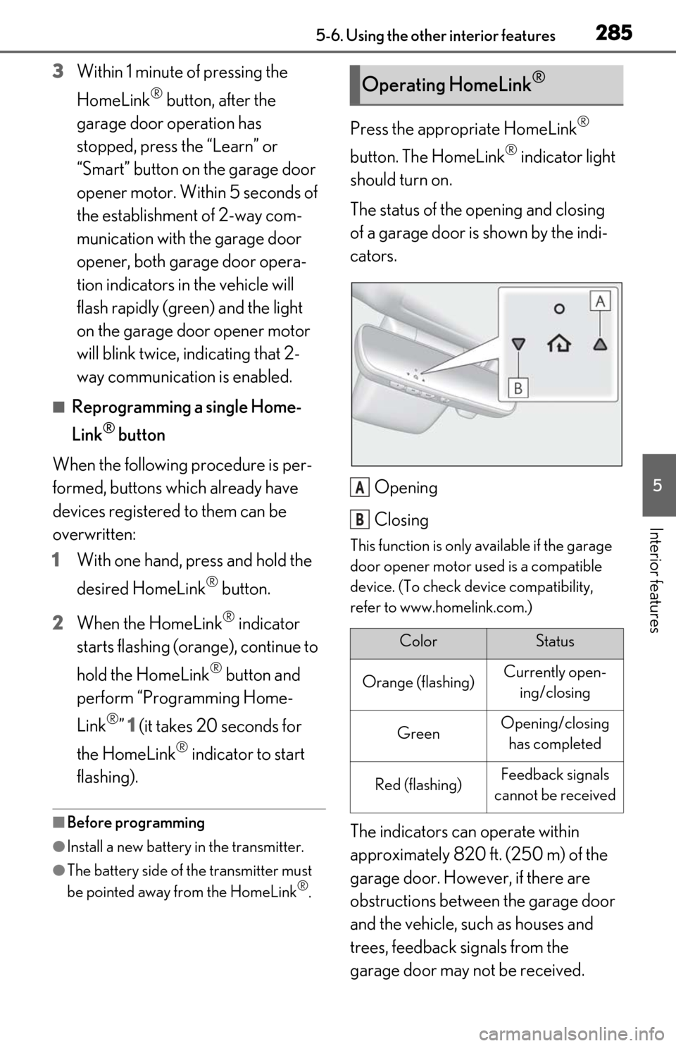
The status of the opening and closing
of a garage door is shown by the indi-
cators.
Opening
Closing
This function is only available if the garage
door opener motor used is a compatible
device. (To check device compatibility,
refer to www.homelink.com.)
The indicators can operate within
approximately 820 ft. (250 m) of the
garage door. However, if there are
obstructions between the garage door
and the vehicle, such as houses and
trees, feedback signals from the
garage door may not be received.
Operating HomeLink®
ColorStatus
Orange (flashing)Currently open-ing/closing
GreenOpening/closing has completed
Red (flashing)Feedback signals
cannot be received
A
B
Page 321 of 444
3216-3. Do-it-yourself maintenance
6
Maintenance and care
When replacing tires or wheels, tire
pressure warning valves and transmit-
ters must also be installed.
When new tire pressure warning
valves and transmitters are installed,
new ID codes must be registered in the
tire pressure warning computer and
the tire pressure warning system must
be initialized. ( P.323)
■When replacing the tires and wheels
If the ID code of the tire pressure warning
valve and transmitter is not registered, the
tire pressure warning system will not work
properly. After driving for about 20 min-
utes, the tire pressure warning light blinks
for 1 minute and stays on to indicate a sys-
tem malfunction.
■The tire pressure warning system
must be initialized in the following
circumstances:
When rotating the tires.
When the tire inflation pressure is
changed when changing traveling
speed.
When the tire inflation pressure is
changed such as when changing tire
size. (When there are multiple spec-
ified pressures)
After registering the ID codes.
( P.323)
When the tire pressure warning system
is initialized, the current tire inflation
pressure is set as the benchmark pres-
sure.
■How to initialize the tire pressure
warning system
1 Park the vehicle in a safe place and
stop the engine for 20 minutes or
more.
Initialization cannot be performed while
the vehicle is moving.
2 Adjust the tire inflation pressure to
the specified cold tire inflation pres-
sure level.
Make sure to adjust the tire pressure to the
specified cold tire infl ation pressure level.
The tire pressure warning system will oper-
ate based on this pressure level.
3 Start the engine. ( P.137)
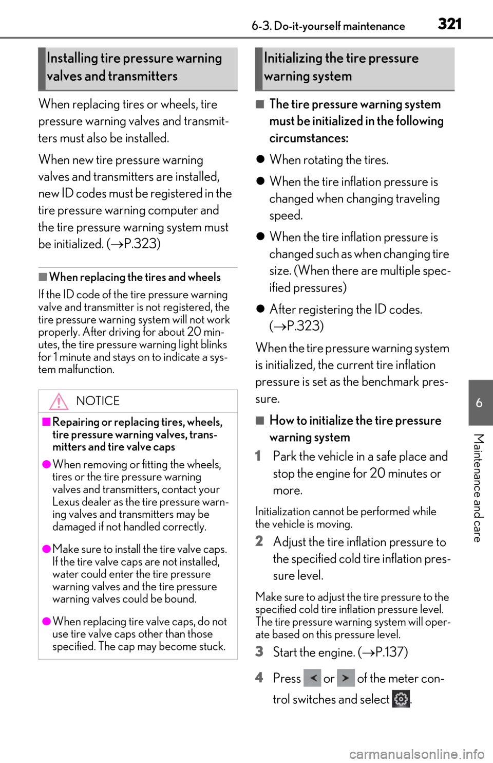
4 Press or of the meter con-
trol switches and select .
Installing tire pressure warning
valves and transmitters
NOTICE
■Repairing or replacing tires, wheels,
tire pressure warning valves, trans-
mitters and tire valve caps
●When removing or fitting the wheels,
tires or the tire pressure warning
valves and transmitters, contact your
Lexus dealer as the tire pressure warn-
ing valves and transmitters may be
damaged if not handled correctly.
●Make sure to install the tire valve caps.
If the tire valve caps are not installed,
water could enter the tire pressure
warning valves and the tire pressure
warning valves could be bound.
●When replacing tire valve caps, do not
use tire valve caps other than those
specified. The cap may become stuck.
Initializing the tire pressure
warning system
Page 339 of 444
339
7
7
When trouble arises
When trouble arises
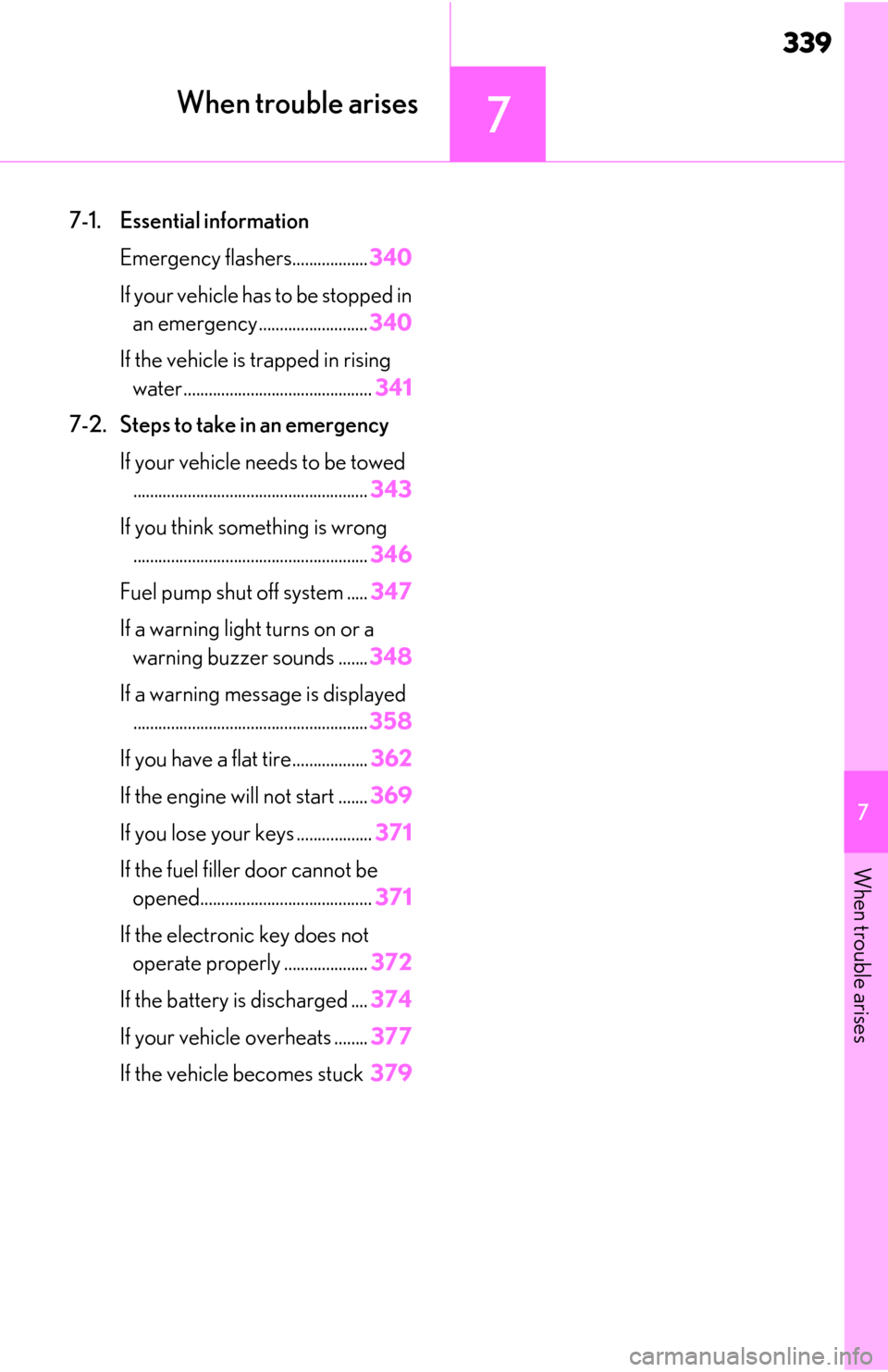
7-1. Essential informationEmergency flashers.................. 340
If your vehicle has to be stopped in an emergency .......................... 340
If the vehicle is trapped in rising water............................................. 341
7-2. Steps to take in an emergency If your vehicle needs to be towed........................................................ 343
If you think something is wrong ........................................................ 346
Fuel pump shut off system ..... 347
If a warning light turns on or a warning buzzer sounds ....... 348
If a warning message is displayed ........................................................ 358
If you have a flat tire.................. 362
If the engine wi ll not start .......369
If you lose your keys .................. 371
If the fuel filler door cannot be opened......................................... 371
If the electronic key does not operate properly .................... 372
If the battery is discharged .... 374
If your vehicle overheats ........ 377
If the vehicle becomes stuck 379
Page 347 of 444
3477-2. Steps to take in an emergency
7
When trouble arises
Vehicle pulls heavily to one side
when driving on a level road
Loss of brake effectiveness, spongy
feeling, pedal almost touches the
floor
Follow the procedure below to restart
the engine after the system is activated.
1Turn the engine switch to ACCES-
SORY mode or turn it off.
2 Restart the engine.Fuel pump shut off system
To minimize the risk of fuel leakage
when the engine stalls or when an
airbag inflates upon collision, the
fuel pump shut off system stops the
supply of fuel to the engine.
Restarting the engine
NOTICE
■Before starting the engine
Inspect the ground under the vehicle.
If you find that fuel has leaked onto the
ground, the fuel sy stem has been dam-
aged and is in need of repair. Do not
restart the engine.