ECU Lexus GS250 2014 Manual PDF
[x] Cancel search | Manufacturer: LEXUS, Model Year: 2014, Model line: GS250, Model: Lexus GS250 2014Pages: 688, PDF Size: 152.64 MB
Page 511 of 688
511 6-3. Do-it-yourself maintenance
6
Maintenance and care
GS350_250_OM_OM30E16E_(EE)
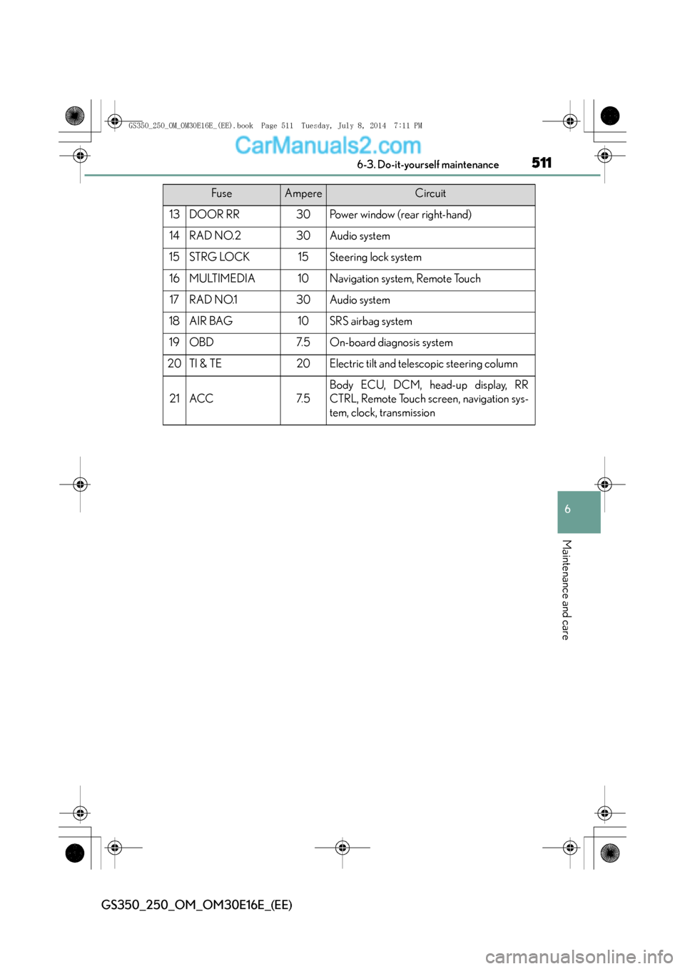
13DOOR RR30Power window (rear right-hand)
14RAD NO.230Audio system
15STRG LOCK15Steering lock system
16MULTIMEDIA10Navigation system, Remote Touch
17RAD NO.130Audio system
18AIR BAG10SRS airbag system
19OBD7. 5On-board diagnosis system
20TI & TE20Electric tilt and telescopic steering column
21ACC7. 5
Body ECU, DCM, head-up display, RR
CTRL, Remote Touch screen, navigation sys-
tem, clock, transmission
FuseAmpereCircuit
GS350_250_OM_OM30E16E_(EE).book Page 511 Tuesday, July 8, 2014 7:11 PM
Page 512 of 688
5126-3. Do-it-yourself maintenance
GS350_250_OM_OM30E16E_(EE)
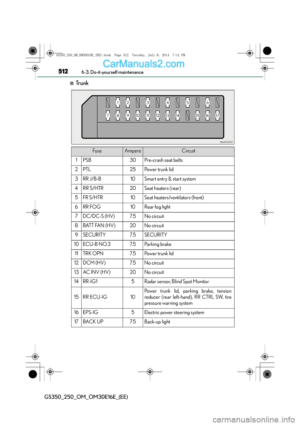
■Tr u n k
FuseAmpereCircuit
1PSB30Pre-crash seat belts
2PTL25Power trunk lid
3RR J/B-B10Smart entry & start system
4RR S/HTR20Seat heaters (rear)
5FR S/HTR10Seat heaters/ventilators (front)
6RR FOG10Rear fog light
7DC/DC-S (HV)7. 5No circuit
8BATT FAN (HV)20No circuit
9SECURITY7. 5SECURITY
10ECU-B NO.37. 5Pa r k in g b ra ke
11TRK OPN7. 5Power trunk lid
12DCM (HV)7. 5No circuit
13AC INV (HV)20No circuit
14RR-IG15Radar sensor, Blind Spot Monitor
15RR ECU-IG10
Power trunk lid, parking brake, tension
reducer (rear left-hand), RR CTRL SW, tire
pressure warning system
16EPS-IG5Electric power steering system
17BACK UP7. 5Back-up light
GS350_250_OM_OM30E16E_(EE).book Page 512 Tuesday, July 8, 2014 7:11 PM
Page 520 of 688
5206-3. Do-it-yourself maintenance
GS350_250_OM_OM30E16E_(EE)
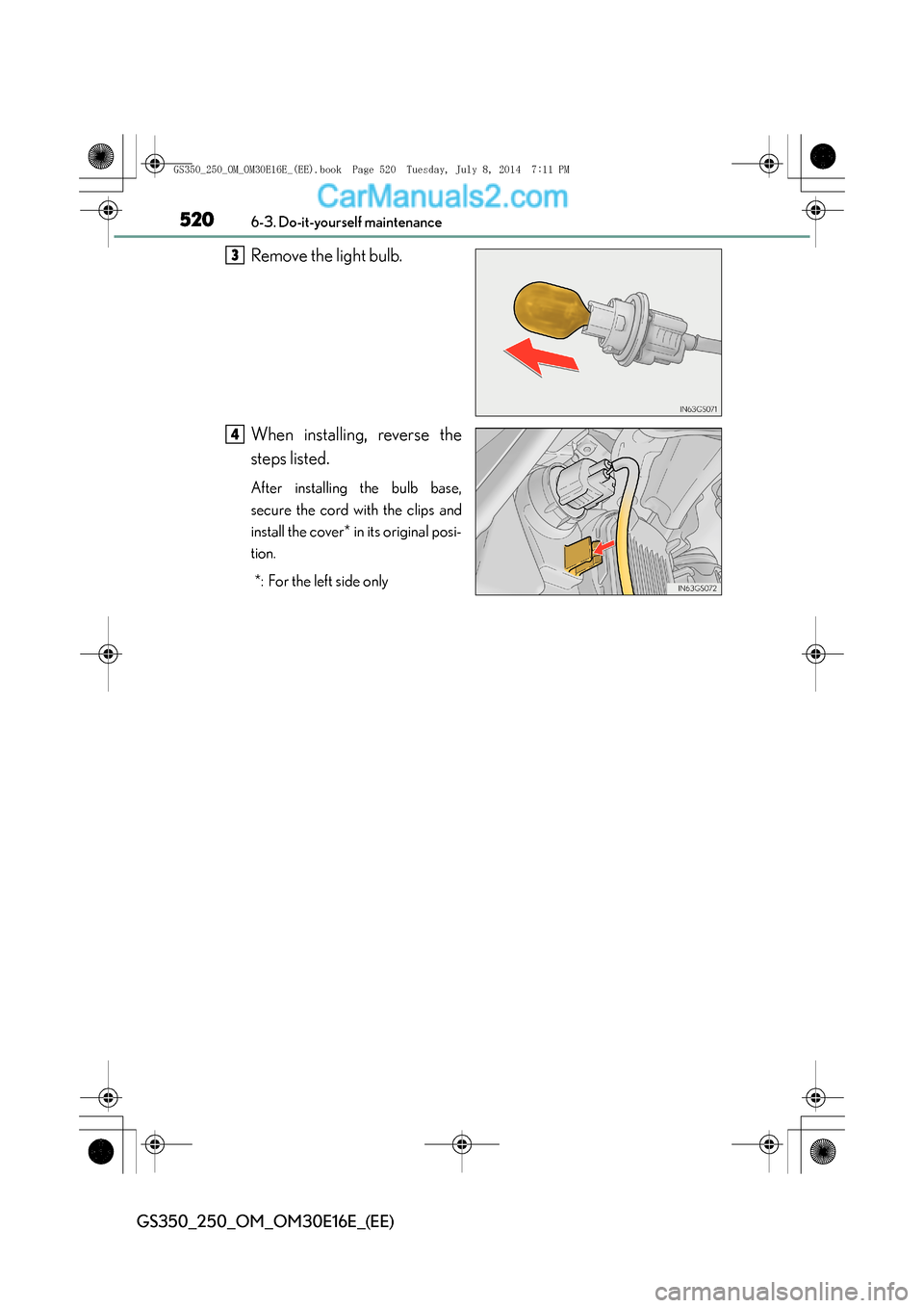
Remove the light bulb.
When installing, reverse the
steps listed.
After installing the bulb base,
secure the cord with the clips and
install the cover* in its original posi-
tion.*: For the left side only
3
4
GS350_250_OM_OM30E16E_(EE).book Page 520 Tuesday, July 8, 201 4 7:11 PM
Page 522 of 688
5226-3. Do-it-yourself maintenance
GS350_250_OM_OM30E16E_(EE)
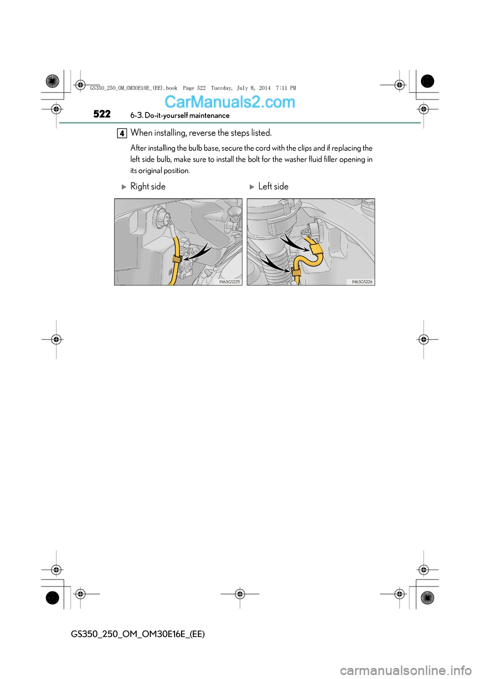
When installing, reverse the steps listed.
After installing the bulb base, secure the cord with the clips and if replacing the
left side bulb, make sure to install the bolt for the washer fluid filler opening in
its original position.
4
�XRight side�XLeft side
GS350_250_OM_OM30E16E_(EE).book Page 522 Tuesday, July 8, 2014 7:11 PM
Page 523 of 688
523 6-3. Do-it-yourself maintenance
6
Maintenance and care
GS350_250_OM_OM30E16E_(EE)
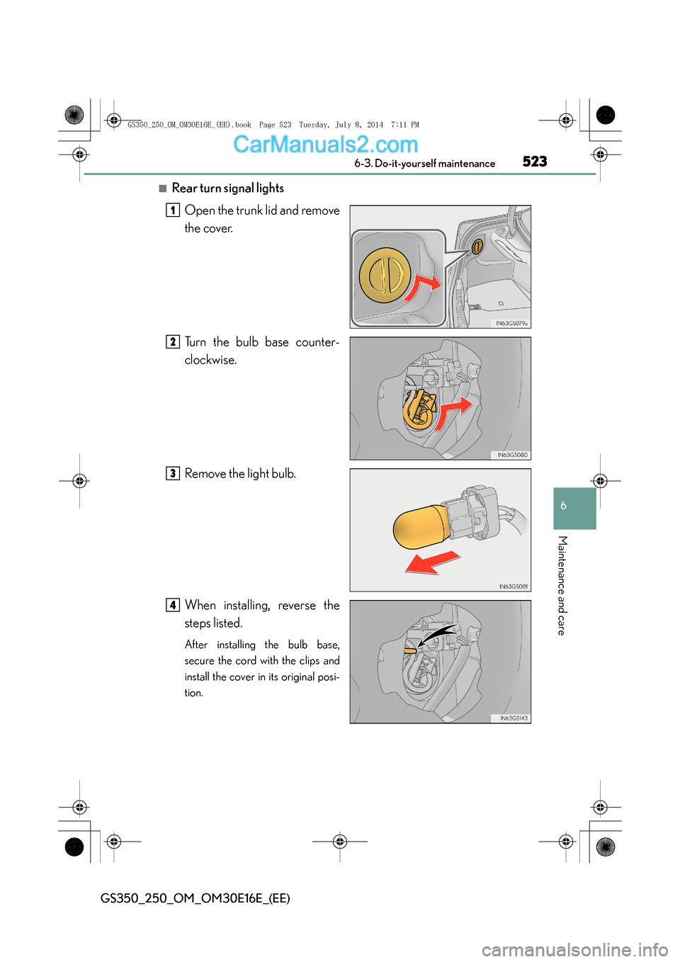
■Rear turn signal lightsOpen the trunk lid and remove
the cover.
Turn the bulb base counter-
clockwise.
Remove the light bulb.
When installing, reverse the
steps listed.
After installing the bulb base,
secure the cord with the clips and
install the cover in its original posi-
tion.
1
2
3
4
GS350_250_OM_OM30E16E_(EE).book Page 523 Tuesday, July 8, 201 4 7:11 PM
Page 527 of 688
527 6-3. Do-it-yourself maintenance
6
Maintenance and care
GS350_250_OM_OM30E16E_(EE)
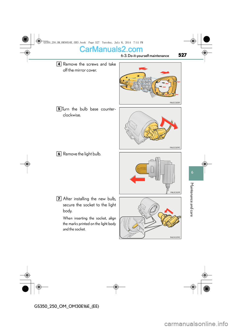
Remove the screws and take
off the mirror cover.
Turn the bulb base counter- clockwise.
Remove the light bulb.
After installing the new bulb,
secure the socket to the light
body.
When inserting the socket, align
the marks printed on the light body
and the socket.
4
5
6
7
GS350_250_OM_OM30E16E_(EE).book Page 527 Tuesday, July 8, 201 4 7:11 PM
Page 528 of 688
5286-3. Do-it-yourself maintenance
GS350_250_OM_OM30E16E_(EE)
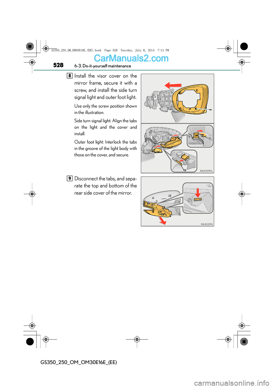
Install the visor cover on the
mirror frame, secure it with a
screw, and install the side turn
signal light and outer foot light.
Use only the screw position shown
in the illustration.
Side turn signal light: Align the tabs
on the light and the cover and
install.
Outer foot light: Interlock the tabs
in the groove of the light body with
those on the cover, and secure.
Disconnect the tabs, and sepa-
rate the top and bottom of the
rear side cover of the mirror.
8
9
GS350_250_OM_OM30E16E_(EE).book Page 528 Tuesday, July 8, 2014 7:11 PM
Page 529 of 688
529 6-3. Do-it-yourself maintenance
6
Maintenance and care
GS350_250_OM_OM30E16E_(EE)
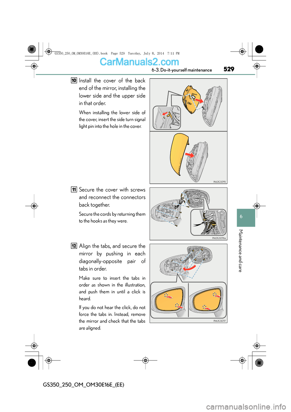
Install the cover of the back
end of the mirror, installing the
lower side and the upper side
in that order.
When installing the lower side of
the cover, insert the side turn signal
light pin into the hole in the cover.
Secure the cover with screws
and reconnect the connectors
back together.
Secure the cords by returning them
to the hooks as they were.
Align the tabs, and secure the
mirror by pushing in each
diagonally-opposite pair of
tabs in order.
Make sure to insert the tabs in
order as shown in the illustration,
and push them in until a click is
heard.
If you do not hear the click, do not
force the tabs in. Instead, remove
the mirror and check that the tabs
are aligned.
10
11
12
GS350_250_OM_OM30E16E_(EE).book Page 529 Tuesday, July 8, 2014 7:11 PM
Page 531 of 688
531 6-3. Do-it-yourself maintenance
6
Maintenance and care
GS350_250_OM_OM30E16E_(EE)
CAUTION
■Replacing light bulbs
●Turn off the lights. Do not attempt to replace the bulb immediately after turning
off the lights.
The bulbs become very hot and may cause burns.
●Do not touch the glass portion of the light bulb with bare hands. When it is
unavoidable to hold the glass portion, use and hold with a clean dry cloth to avoid
getting moisture and oils on the bulb.
Also, if the bulb is scratched or dropped, it may blow out or crack.
●Fully install light bulbs and any parts used to secure them. Failure to do so may
result in heat damage, fire, or water entering the headlight unit. This may damage
the headlights or cause condensation to build up on the lens.
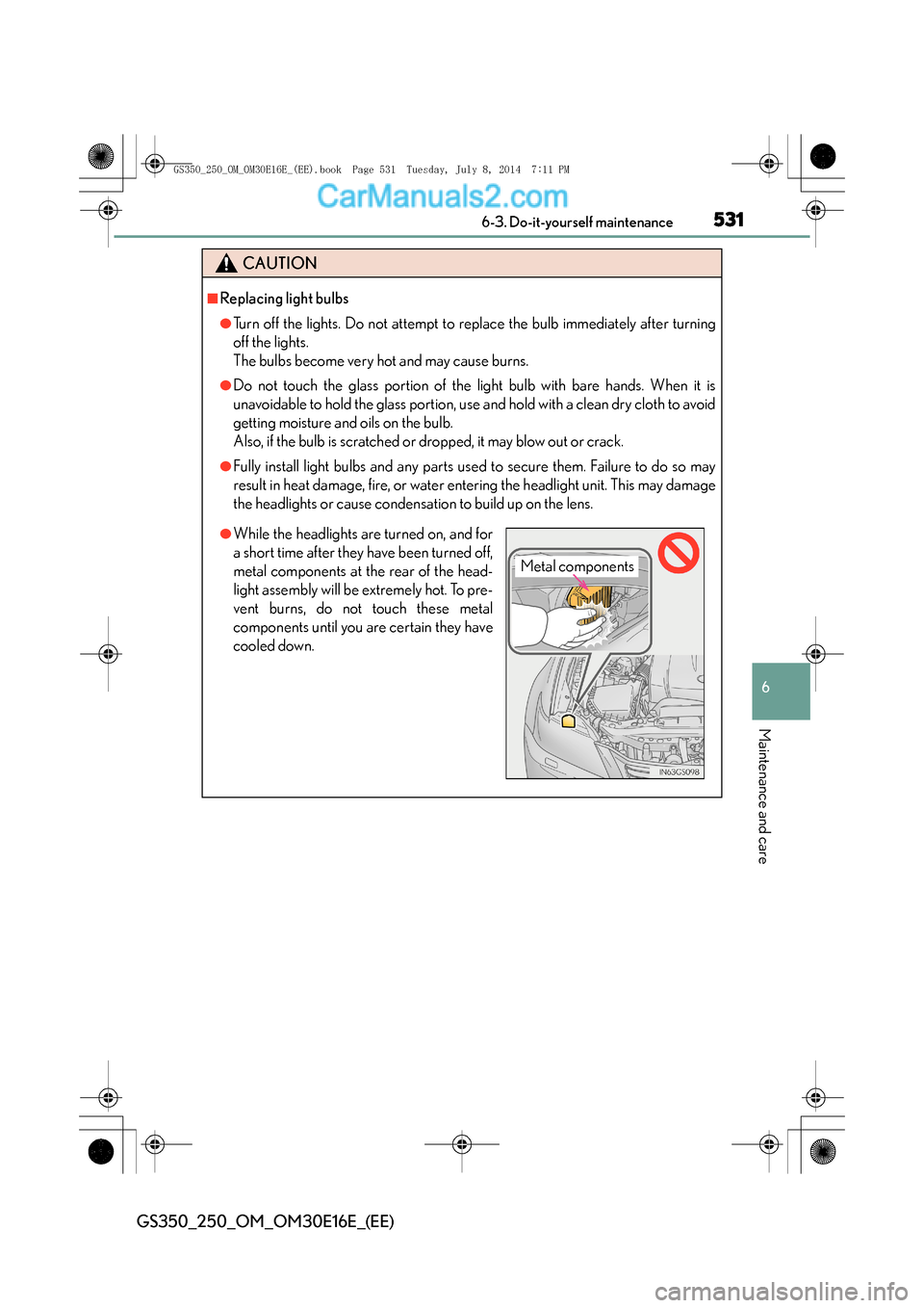
●While the headlights are turned on, and for
a short time after they have been turned off,
metal components at the rear of the head-
light assembly will be extremely hot. To pre-
vent burns, do not touch these metal
components until you are certain they have
cooled down.
Metal components
GS350_250_OM_OM30E16E_(EE).book Page 531 Tuesday, July 8, 2014 7:11 PM
Page 535 of 688
535
7
7-1. Essential information
When trouble arises
GS350_250_OM_OM30E16E_(EE)
If your vehicle has to be stopped in an emergency
Steadily step on the brake pedal wi
th both feet and firmly depress it.
Do not pump the brake pedal repeatedly as this will increase the effort required to
slow the vehicle.
Shift the shift lever to N.
�XIf the shift lever is shifted to N
After slowing down, stop the vehicle in a safe place by the road.
Stop the engine.
�XIf the shift lever cannot be shifted to N
Keep depressing the brake pedal with both feet to reduce vehicle
speed as much as possible.
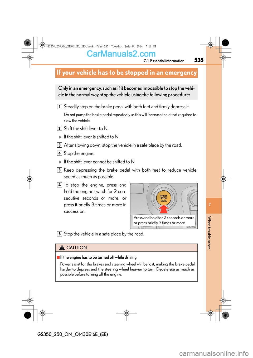
To stop the engine, press and
hold the engine switch for 2 con-
secutive seconds or more, or
press it briefly 3 times or more in
succession.
Stop the vehicle in a safe place by the road.
Only in an emergency, such as if it becomes impossible to stop the vehi-
cle in the normal way, stop the ve hicle using the following procedure:
1
2
3
4
3
Press and hold for 2 seconds or more
or press briefly 3 times or more
4
CAUTION
■If the engine has to be turned off while driving
Power assist for the brakes and steering wheel will be lost, making the brake pedal
harder to depress and the steering wheel heavier to turn. Decelerate as much as
possible before turning off the engine.
5
GS350_250_OM_OM30E16E_(EE).book Page 535 Tuesday, July 8, 201 4 7:11 PM