inflation pressure Lexus GS350 2017 Owner's Manual
[x] Cancel search | Manufacturer: LEXUS, Model Year: 2017, Model line: GS350, Model: Lexus GS350 2017Pages: 676, PDF Size: 67.73 MB
Page 15 of 676
15
Pictorial index
GS350_200t_GS F_OM_OM30F83E_(EE)
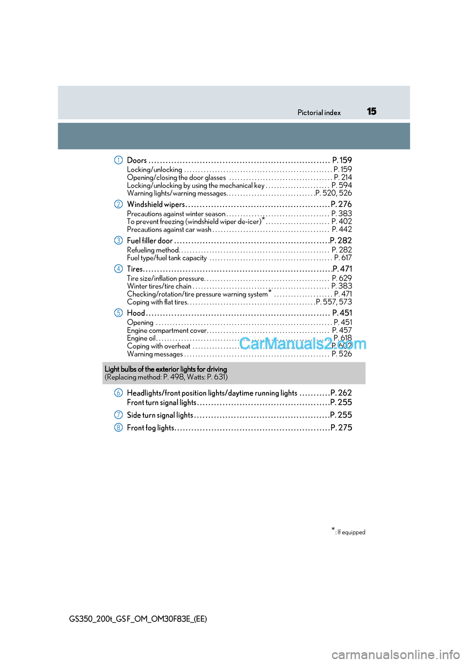
Doors . . . . . . . . . . . . . . . . . . . . . . . . . . . . . . . . . . . . . . . . . . . . . . . . . . . . . . . . . . . . . . . . P. 159
Locking/unlocking . . . . . . . . . . . . . . . . . . . . . . . . . . . . . . . . . . . . . . . . . . . . . . . . . . . . . P. 159
Opening/closing the door glasses . . . . . . . . . . . . . . . . . . . . . . . . . . . . . . . . . . . . . P. 214
Locking/unlocking by using the mechanical key . . . . . . . . . . . . . . . . . . . . . . . P. 594
Warning lights/warning messages. . . . . . . . . . . . . . . . . . . . . . . . . . . . . . . .P. 520, 526
Windshield wipers . . . . . . . . . . . . . . . . . . . . . . . . . . . . . . . . . . . . . . . . . . . . . . . . . . . P. 276
Precautions against winter season . . . . . . . . . . . . . . . . . . . . . . . . . . . . . . . . . . . . . P. 383
To prevent freezing (windshield wiper de-icer) *. . . . . . . . . . . . . . . . . . . . . . . P. 402
Precautions against car wash . . . . . . . . . . . . . . . . . . . . . . . . . . . . . . . . . . . . . . . . . . P. 442
Fuel filler door . . . . . . . . . . . . . . . . . . . . . . . . . . . . . . . . . . . . . . . . . . . . . . . . . . . . . . .P . 282
Refueling method. . . . . . . . . . . . . . . . . . . . . . . . . . . . . . . . . . . . . . . . . . . . . . . . . . . . . . P. 282
Fuel type/fuel tank capacity . . . . . . . . . . . . . . . . . . . . . . . . . . . . . . . . . . . . . . . . . . . . P. 617
Tires. . . . . . . . . . . . . . . . . . . . . . . . . . . . . . . . . . . . . . . . . . . . . . . . . . . . . . . . . . . . . . . . . . .P. 471
Tire size/inflation pressure. . . . . . . . . . . . . . . . . . . . . . . . . . . . . . . . . . . . . . . . . . . . . P. 629
Winter tires/tire chain . . . . . . . . . . . . . . . . . . . . . . . . . . . . . . . . . . . . . . . . . . . . . . . . . P. 38 3
Checking/rotation/tire pressure warning system * . . . . . . . . . . . . . . . . . . . . . P. 471
Coping with flat tires. . . . . . . . . . . . . . . . . . . . . . . . . . . . . . . . . . . . . . . . . . . . . . P. 557, 573
Hood . . . . . . . . . . . . . . . . . . . . . . . . . . . . . . . . . . . . . . . . . . . . . . . . . . . . . . . . . . . . . . . . . P. 451
Opening . . . . . . . . . . . . . . . . . . . . . . . . . . . . . . . . . . . . . . . . . . . . . . . . . . . . . . . . . . . . . . . P. 451
Engine compartment cover. . . . . . . . . . . . . . . . . . . . . . . . . . . . . . . . . . . . . . . . . . . . P. 457
Engine oil . . . . . . . . . . . . . . . . . . . . . . . . . . . . . . . . . . . . . . . . . . . . . . . . . . . . . . . . . . . . . . . P. 618
Coping with overheat . . . . . . . . . . . . . . . . . . . . . . . . . . . . . . . . . . . . . . . . . . . . . . . . . P. 602
Warning messages . . . . . . . . . . . . . . . . . . . . . . . . . . . . . . . . . . . . . . . . . . . . . . . . . . . . P. 526
Headlights/front position lights/daytime running lights . . . . . . . . . . . P. 262
Front turn signal lights . . . . . . . . . . . . . . . . . . . . . . . . . . . . . . . . . . . . . . . . . . . . . . . P. 255
Side turn signal lights . . . . . . . . . . . . . . . . . . . . . . . . . . . . . . . . . . . . . . . . . . . . . . . . P. 255
Front fog lights. . . . . . . . . . . . . . . . . . . . . . . . . . . . . . . . . . . . . . . . . . . . . . . . . . . . . . . P. 2751
2
3
4
5
Light bulbs of the exterior lights for driving
(Replacing method: P. 498, Watts: P. 631)
*: If equipped
6
7
8
Page 124 of 676
1242. Instrument cluster
GS350_200t_GS F_OM_OM30F83E_(EE)
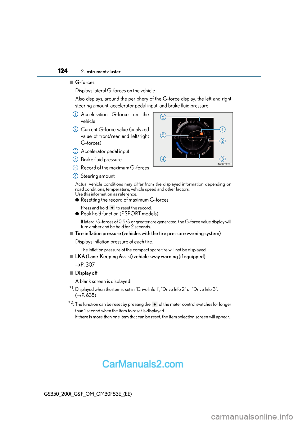
■G-forces
Displays lateral G-forces on the vehicle
Also displays, around the periphery of the G-force display, the left and right
steering amount, accelerator pedal input, and brake fluid pressure
Acceleration G-force on the
vehicle
Current G-force value (analyzed
value of front/rear and left/right
G-forces)
Accelerator pedal input
Brake fluid pressure
Record of the maximum G-forces
Steering amount
Actual vehicle conditions may differ from the displayed information depending on
road conditions, temperature, vehicle speed and other factors.
Use this information as reference. ● Resetting the record of maximum G-forces
Press and hold to reset the record.
● Peak hold function (F SPORT models)
If lateral G-forces of 0.5 G or greater are generated, the G-force value display will
turn amber and be held for 2 seconds.
■Tire inflation pressure (vehicles with the tire pressure warning system)
Displays inflation pressure of each tire.
The inflation pressure of the compac t spare tire will not be displayed.
■LKA (Lane-Keeping Assist) vehi cle sway warning (if equipped)
P. 307
■Display off
A blank screen is displayed
* 1
: Displayed when the item is set in “Drive Info 1”, “Drive Info 2” or “Drive Info 3”.
( P. 635)
* 2
: The function can be reset by pressing the of the meter control switches for longer
than 1 second when the item to reset is displayed.
If there is more than one item that can be reset, the item selection screen will appear.
1
2
3
4
5
6
Page 127 of 676
127
2. Instrument cluster
2
Instrument cluster
GS350_200t_GS F_OM_OM30F83E_(EE)
■G-force display
●The G-force values may not be zero even when the vehicle is parked, such as when it is
parked on an incline.
●Depending on the vehicle usage conditions, the brake fluid pressure display may not
reach its maximum reading even though the brake pedal is fully depressed.
●If a battery terminal is disconnected and reconnected, the steering amount display may
be disabled temporarily. After driving the ve hicle for a while, the display will be enabled.
■Suspension of the settings display
In the following situations, the settings disp lay using the meter control switches will be
suspended.
●When a warning message appears on the multi-information display
●When the vehicle begins to move
■Tire inflation pressure (if equipped)
●It may take a few minutes to display the tire inflation pressure afte r the engine switch is
turned to IGNITION ON mode. It may also take a few minutes to display the tire infla-
tion pressure after inflation pressure has been adjusted.
●“---” may be displayed if the tire information cannot be determined due to unfavorable
radio wave conditions.
●Tire inflation pressure changes with temperature. The displayed values may also be dif-
ferent from the values measured using a tire pressure gauge.
■When disconnecting and reconnecting battery terminals
The drive information will be reset.
■Liquid crystal display P. 111
Page 136 of 676
1362. Instrument cluster
GS350_200t_GS F_OM_OM30F83E_(EE)
●Switching the display
To switch to advanced display, press .
To return to normal display, press .
● Resetting the record of maximum G-forces
With the record of maximum G-forces displayed, press and hold to
reset the display.
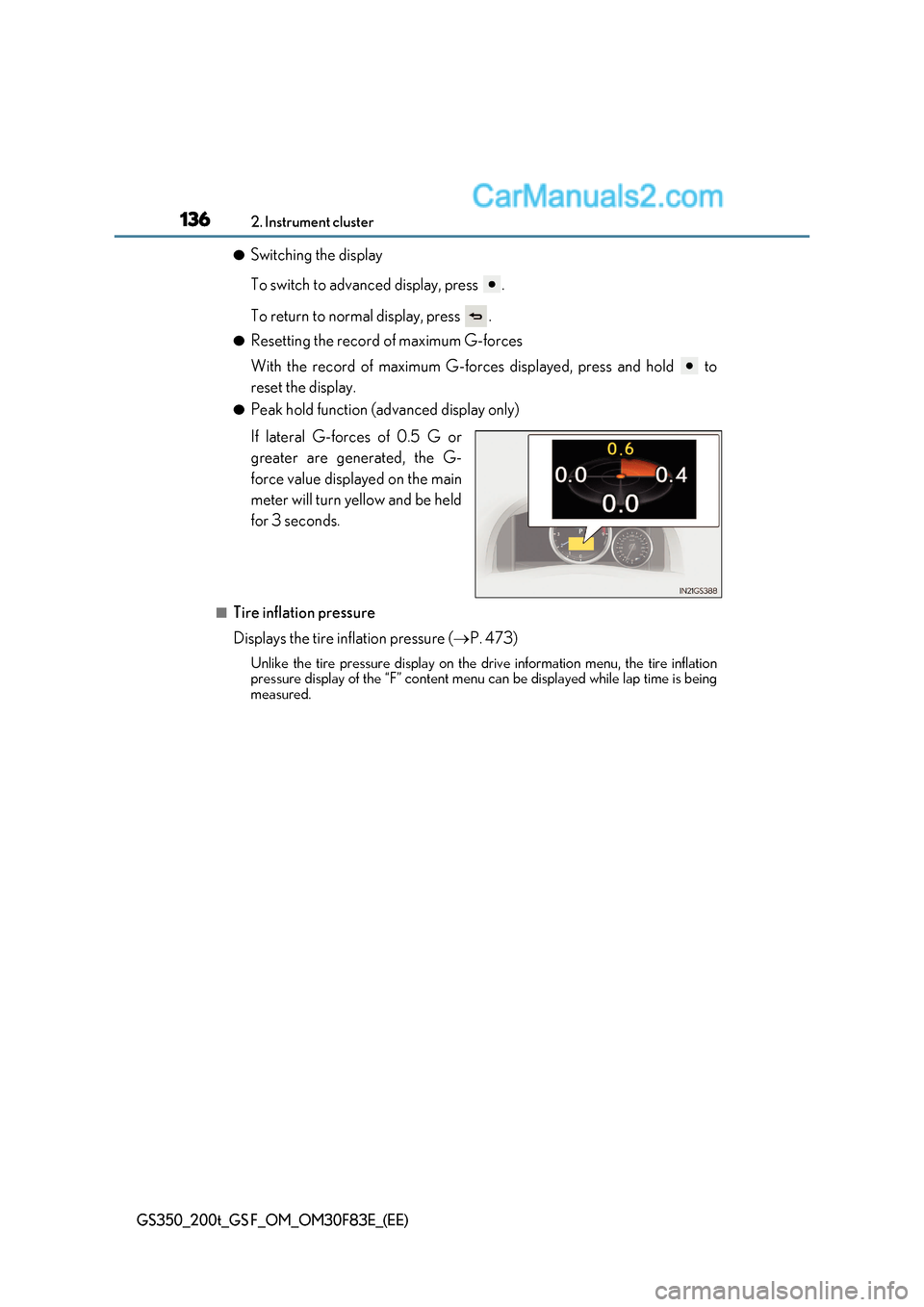
● Peak hold function (advanced display only)
If lateral G-forces of 0.5 G or
greater are generated, the G-
force value displayed on the main
meter will turn yellow and be held
for 3 seconds.
■Tire inflation pressure
Displays the tire inflation pressure ( P. 473)
Unlike the tire pressure display on the dr ive information menu, the tire inflation
pressure display of the “F” content menu can be displayed while lap time is being
measured.
Page 139 of 676
139
2. Instrument cluster
2
Instrument cluster
GS350_200t_GS F_OM_OM30F83E_(EE)
■Start-up display
When the engine is started, the name of the vehicle is displayed on the multi-information
display.
While the start-up display is being displayed, the meter display cannot be changed even
if the drive mode is changed. When the start-up display is finished, the meter display for
the currently selected mode will be displayed.
■Torque distribution display (if equipped)
Torque distribution may not be displayed correctly in some cases, such as when the vehi-
cle passes over road expansion joints.
■G-force display
●The G-force values may not be zero even when the vehicle is parked, such as when it is
parked on an incline.
●The steering amount, accelerator pedal input, and brake fluid pressure displays are dis-
abled until the engine has warmed up (the variable red zone of the tachometer has
retracted to 7300 r/min).
After the engine has warmed up, these displays will be enabled.
●Depending on the vehicle usage conditions, the brake fluid pressure display may not
reach its maximum reading even though the brake pedal is fully depressed.
●If a battery terminal is disconnected and reconnected, the steering amount display may
be disabled temporarily. After driving the ve hicle for a while, the display will be enabled.
■Suspension of the settings display
In the following situations, operation of th e settings display will be temporarily sus-
pended.
●When a warning message appears on the multi-information display
●When the vehicle begins to move
■Tire inflation pressure
●It may take a few minutes to display the tire inflation pressure afte r the engine switch is
turned to IGNITION ON mode. It may also take a few minutes to display the tire infla-
tion pressure after inflation pressure has been adjusted.
●“---” may be displayed if the tire positi on information cannot be determined due to
unfavorable radio wave conditions.
●Tire inflation pressure changes with temperature. The displayed values may also be dif-
ferent from the values measured using a tire pressure gauge.
■When disconnecting and reconnecting battery terminals
The following information data will be reset:
●Lap timer: Measured lap times, history
●G-force: Record of the maximum G-forces
■Using the lap timer
If the engine is stopped while a lap is being timed, the lap timer will stop and the lap time
up to that point will be recorded.
■Liquid crystal display P. 119
Page 236 of 676
2364-1. Before driving
GS350_200t_GS F_OM_OM30F83E_(EE)
■Tire information
●Increase the tire inflation pressure to 20.0 kPa (0.2 kgf/cm 2
or bar, 3 psi) greater than
the recommended value when towing. ( P. 629)
●Increase the air pressure of the trailer tires in accordance with the total trailer weight
and according to the values recommended by the manufacturer of your trailer.
■Trailer lights
●Please consult any authorized Lexus retailer or Lexus authorized repairer, or any reli-
able repairer when installing trailer lights, as incorrect installation may cause damage to
the vehicle’s lights. Please take care to comply with your state’s laws when installing
trailer lights.
●Check that the turn signal lights and stoplights are operating correctly every time you
hitch up the trailer. Directly wiring up to your vehicle may damage the electrical systemand stop the lights from functioning correctly.
■Break-in schedule
Lexus recommends that vehicles fitted with new power train components should not be
used for towing trailers for the first 800 km (500 miles).
■Safety checks before towing
●Check that the maximum load limit for the towing hitch/bracket and hitch ball is not
exceeded. Bear in mind that the coupling weight of the trailer will add to the load
exerted on the vehicle. Also make sure that the total load exerted on the vehicle is
within the range of the weight limits. ( P. 234)
●Ensure that the trailer load is secure.
●Supplementary outside rear view mirrors should be added to the vehicle if the traffic
behind cannot be clearly seen with standard mirrors. Adjust the extending arms of
these mirrors on both sides of the vehicle so that they always provide maximum visibility
of the road behind.
■Maintenance
●Maintenance must be performed more frequently when using the vehicle for towing
due to the greater weight burden placed on the vehicle compared to normal driving.
●Retighten all bolts securing the hitching ball and bracket after towing for approximately
1000 km (600 miles).
NOTICE
■When the rear bumper strengthening material is aluminum
Ensure the steel bracket part does not come directly in contact with that area.
When steel and aluminum come into contact, there is a reaction similar to corrosion,
which will weaken the section concerned and may result in damage. Apply a rust inhib-
itor to parts that will come in co ntact when attaching a steel bracket.
Page 310 of 676
3104-5. Using the driving support systems
GS350_200t_GS F_OM_OM30F83E_(EE)
WARNING
■Situations unsuitable for LKA system
Do not use the LKA system in the following situations.
The system may not operate properly and le ad to an accident, resulting in death or
serious injury.
●A spare tire, tire chains, etc. are equipped.
●When the tires have been excessively worn, or when the tire inflation pressure is low.
●Tires which differ by structure, manufacturer, brand or tread pattern are used.
●Objects or patterns that could be mistaken for white (yellow) lines are present on the
side of the road (guardrails, cu rbs, reflective poles, etc.).
●Vehicle is driven on a snow-covered road.
●White (yellow) lines are difficult to see due to rain, snow, fog, dust, etc.
●Asphalt repair marks, white (yellow) line ma rks, etc. are present due to road repair.
●Vehicle is driven in a temporary lane or restricted lane due to construction work.
●Vehicle is driven on a road surface which is slippery due to rainy weather, fallen snow,
freezing, etc.
●Vehicle is driven in traffic lanes other than on highways and freeways.
●Vehicle is driven in a construction zone.
●Vehicle is towing a trailer or another vehicle. (vehicles with towing package)
■Preventing LKA system malfunctions and operations performed by mistake
●Do not modify the headlights or place stickers, etc. on the surface of the lights.
●Do not modify the suspension etc. If the suspension etc. needs to be replaced, con-
tact any authorized Lexus retailer or Le xus authorized repairer, or any reliable
repairer.
●Do not install or place anything on the hood or grille. Also, do not install a grille guard
(bull bars, kangaroo bar, etc.).
●If your windshield needs repairs, contac t any authorized Lexus retailer or Lexus
authorized repairer, or any reliable repairer.
Page 319 of 676
319
4-5. Using the driving support systems
4
Driving
GS350_200t_GS F_OM_OM30F83E_(EE)
WARNING
■Before using LDA system
Do not rely solely upon the LDA system. The LDA system does not automatically drive
the vehicle or reduce the amount of attention that must be paid to the area in front of
the vehicle. The driver must always assume full responsibility for driving safely by pay-
ing careful attention to the surrounding conditions and operating the steering wheel to
correct the path of the vehicle. Also, the driver must take adequate breaks when
fatigued, such as from driving for a long period of time.
Failure to perform appropriate driving operat ions and pay careful attention may lead to
an accident, resulting in death or serious injury.
■To avoid operating LDA system by mistake
When not using the LDA system, use the LDA switch to turn the system off.
■Situations unsuitable for LDA system
Do not use the LDA system in the following situations.
The system may not operate properly and le ad to an accident, resulting in death or
serious injury.
●A spare tire, tire chains, etc. are equipped.
●When the tires have been excessively worn, or when the tire inflation pressure is low.
●Tires which differ by structure, manufacturer, brand or tread pattern are used.
●Objects or patterns that could be mistaken for white (yellow) lines are present on the
side of the road (guardrails, cu rbs, reflective poles, etc.).
●Vehicle is driven on a snow-covered road.
●White (yellow) lines are difficult to see due to rain, snow, fog, dust, etc.
●Asphalt repair marks, white (yellow) line ma rks, etc. are present due to road repair.
●Vehicle is driven in a temporary lane or restricted lane due to construction work.
●Vehicle is driven on a road surface which is slippery due to rainy weather, fallen snow,
freezing, etc.
●Vehicle is driven in traffic lanes other than on highways and freeways.
●Vehicle is driven in a construction zone.
■Preventing LDA system malfunctions and operations performed by mistake
●Do not modify the headlights or place stickers, etc. on the surface of the lights.
●Do not modify the suspension etc. If the suspension etc. needs to be replaced, con-
tact any authorized Lexus retailer or Le xus authorized repairer, or any reliable
repairer.
●Do not install or place anything on the hood or grille. Also, do not install a grille guard
(bull bars, kangaroo bar, etc.).
●If your windshield needs repairs, contac t any authorized Lexus retailer or Lexus
authorized repairer, or any reliable repairer.
Page 439 of 676
439
6Maintenance and care
GS350_200t_GS F_OM_OM30F83E_(EE)
6-1. Maintenance and careCleaning and protecting the vehicle exterior ................ 440
Cleaning and protecting the vehicle interior.................. 444
6-2. Maintenance Maintenance requirements ............................ 447
6-3. Do-it-yourself maintenance Do-it-yourself service precautions................................ 449
Hood ................................................ 451
Positioning a floor jack ............ 452
Engine compartment ............... 454
Tires ...................................................471
Tire inflation pressure ..............485
Wheels ........................................... 487
Air conditioning filter ...............489
Electronic key battery............... 491
Checking and replacing fuses.............................................. 493
Light bulbs.....................................498
Page 473 of 676
473
6-3. Do-it-yourself maintenance
6
Maintenance and care
GS350_200t_GS F_OM_OM30F83E_(EE)
Your vehicle is equipped with a tire pressu re warning system that uses tire pres-
sure warning valves and transmitters to detect low tire inflation pressure bef ore
serious problems arise.
Vehicles without the tire inflation pressure display function
If the tire pressure drops below a predetermined level, the driver is warned by a
warning light. ( P. 521)
Vehicles with the tire inflation pressure display function
● If the tire pressure drops below a predetermined level, the driver is warned b y
the multi-information display and a warning light. ( P. 518, 524)
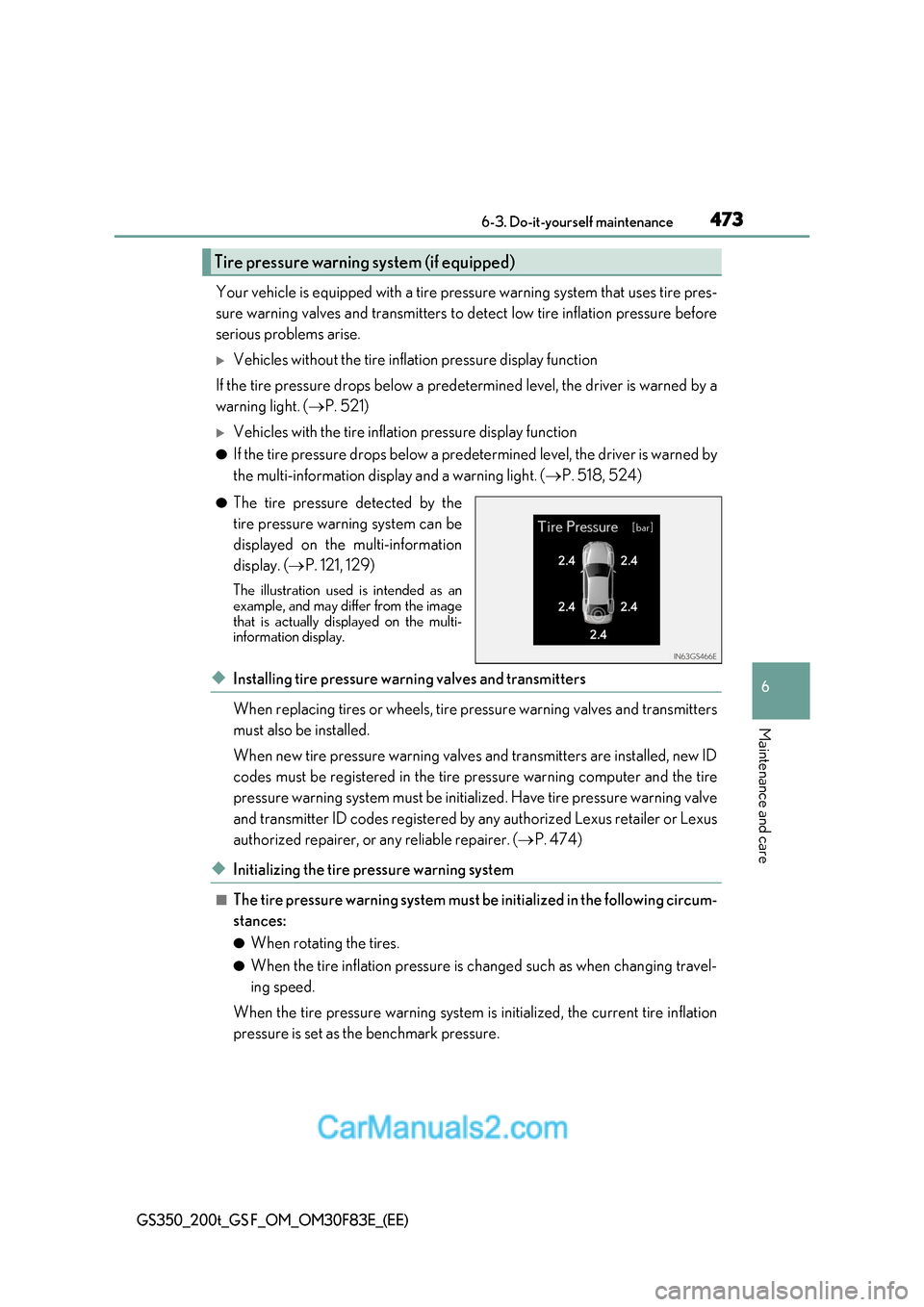
● The tire pressure detected by the
tire pressure warning system can be
displayed on the multi-information
display. ( P. 121, 129)
The illustration used is intended as an
example, and may differ from the image
that is actually displayed on the multi-
information display.
◆Installing tire pressure warning valves and transmitters
When replacing tires or wheels, tire pressure warning valves and transmitters
must also be installed.
When new tire pressure warning valves and transmitters are installed, new ID
codes must be registered in the tire pressure warning computer and the tire
pressure warning system must be initialized. Have tire pressure war ning valve
and transmitter ID codes registered by any authorized Lexus retailer or Lexus
authorized repairer, or any reliable repairer. ( P. 474)
◆Initializing the tire pressure warning system
■The tire pressure warning system must be initialized in the following circum-
stances: ● When rotating the tires.
● When the tire inflation pressure is changed such as when changing travel-
ing speed.
When the tire pressure warning system is initialized, the current tire inflation
pressure is set as the benchmark pressure.
Tire pressure warning system (if equipped)