check LEXUS IS300 2022 Service Manual
[x] Cancel search | Manufacturer: LEXUS, Model Year: 2022, Model line: IS300, Model: LEXUS IS300 2022Pages: 440, PDF Size: 22.72 MB
Page 189 of 440

1874-5. Using the driving support systems
4
Driving
Vehicle-to-vehicle distance switch
Multi-information display
Set speed
IndicatorsCruise control switch
Dynamic radar cruise con-
trol with full-speed range
In vehicle-to-vehicle distance con-
trol mode, the vehicle automati-
cally accelerates, decelerates and
stops to match the speed changes
of the preceding vehicle even if the
accelerator pedal is not depressed.
In constant speed control mode,
the vehicle runs at a fixed speed.
Use the dynamic radar cruise con-
trol with full-speed range on free-
ways and highways.
Vehicle-to-vehicle distance con-
trol mode ( P.189)
Constant speed control mode
( P.194)
System Components
A
B
C
D
WARNING
■Before using dynamic radar cruise
control with full-speed range
●Driving safely is th e sole responsibility
of the driver. Do not rely solely on the
system, and drive safely by always pay-
ing careful attention to your
surroundings.
●The dynamic radar cruise control with
full-speed range provides driving
assistance to reduce the driver’s bur-
den. However, there are limitations to
the assistance provided.
Read the following conditions care-
fully. Do not overly rely on this system
and always drive carefully.
• When the sensor ma y not be correctly
detecting the vehicle ahead:
P.195
• Conditions under which the vehi- cle-to-vehicle distance control mode
may not function correctly:
P.196
●Set the speed appropriately depend-
ing on the speed limit, traffic flow, road
conditions, weather conditions, etc.
The driver is responsible for checking
the set speed.
●Even when the system is functioning
normally, the condition of the preced-
ing vehicle as detected by the system
may differ from the condition
observed by the driver. Therefore, the
driver must always remain alert, assess
the danger of each situation and drive
safely. Relying solely on this system or
assuming the system ensures safety
while driving can lead to an accident,
resulting in death or serious injury.
●Switch the dynamic radar cruise con-
trol with full-speed range setting to off,
using the “ON/OFF” button when not
in use.
E
Page 205 of 440

2034-5. Using the driving support systems
4
Driving
*:If equipped
■Types of sensors
Except F SPORT modelsFront corner sensors
Front center sensors
Rear corner sensors
Rear center sensors
F SPORT modelsFront corner sensors
Front center sensors
Rear corner sensors
Rear center sensors
■Display
When the sensors detect an object,
such as a wall, a graphic is shown on
the multi-information display and Cen-
ter Display depending on the position
and distance to the object.
Multi-information display
Front corner sensor detection
Front center sensor detection
Rear corner sensor detection
Rear center sensor detection
Center Display (vehicles with a
Lexus parking assist monitor)
A graphic is shown when the Lexus park-
Intuitive parking assist*
The distance from your vehicle to
objects, such as a wall, when paral-
lel parking or maneuvering into a
garage is measured by the sensors
and communicated via the
multi-information display, Center
Display and a buzzer. Always check
the surrounding area when using
this system.
System components
A
B
C
D
A
B
C
D
A
B
C
D
Page 212 of 440

2104-5. Using the driving support systems
Meter control switches
The RCTA function can be turned on/off.
When the RCTA function is disabled, the
RCTA OFF indicator illuminates.
Outside rear view mirror indicators
When a vehicle approaching from the right
or left at the rear of the vehicle is detected,
both outside rear view mirror indicators
will flash.
Center Display
If a vehicle approaching from the right or
left at the rear of the vehicle is detected,
the RCTA icon ( P.212) for the detected
side will be displaye d on the Center Dis-
play. This illustration shows an example of a
vehicle approaching from both sides of the
vehicle.
RCTA buzzer
If a vehicle approaching from the right or
left at the rear of the vehicle is detected, a
buzzer will sound. The buzzer also sounds
for approximately 1 second immediately
RCTA (Rear Cross Traffic
Alert) function
The RCTA function uses the BSM
rear side radar sensors installed on
the inner side of the rear bumper.
This function is intended to assist
the driver in checking areas that
are not easily visible when backing
up.
WARNING
■Cautions regarding the use of the
function
There is a limit to the degree of recogni-
tion accuracy and control performance
that this system can provide, do not
overly rely on this system. The driver is
always responsible for paying attention
to the vehicle’s surro undings and driving
safely. ( P.197)
■To ensure the system can operate
properly
P.197
System components
A
B
C
D
Page 218 of 440
2164-5. Using the driving support systems
*:If equipped
■Parking Support Brake function
(static objects)
P.222
■Parking Support Brake function
(rear-crossing vehicles)
P.225
PKSB (Parking Support
Brake)
*
The Parking Support Brake system
consists of the following functions
that operate when driving at a low
speed or backing up, such as when
parking. When the system deter-
mines that the possibility of a colli-
sion with a detected object is high, a
warning operates to urge the driver
to take evasive action. If the system
determines that the possibility of a
collision with a detected object is
extremely high, the brakes are
automatically applie d to help avoid
the collision or help reduce the
impact of the collision.
PKSB (Parking Support Brake)
system
WARNING
■Cautions regarding the use of the sys-
tem
Do not overly rely on the system, as
doing so may lead to an accident.
●The driver is solely responsible for safe
driving. Always drive carefully, taking
care to observe your surroundings.
The Parking Support Brake system is
designed to provide support to lessen
the severity of collisions. However, it
may not operate in some situations.
●The Parking Support Brake system is
not designed to stop the vehicle com-
pletely. Additionally, even if the system
has stopped the vehicl e, it is necessary
to depress the brake pedal immedi-
ately as brake control will be canceled
after approximately 2 seconds.
●It is extremely dangerous to check the
system operations by intentionally
driving the vehicle into the direction of
a wall, etc. Never attempt such actions.
■When to disable the Parking Support
Brake
In the following situations, disable the
Parking Support Brake as the system
may operate even though there is no
possibility of a collision.
●When inspecting the vehicle using a
chassis roller, chassis dynamo or free
roller
●When loading the vehicle onto a boat,
truck or other transport vessel
●If the suspension has been modified or
tires of a size othe r than specified are
installed
●If the front of the vehicle is raised or
lowered due to the carried load
●When equipment that may obstruct a
sensor is installed, such as a towing
eyelet, bumper protector (an addi-
tional trim strip, etc.), bicycle carrier, or
snow plow
●When using automatic car washing
devices
●If the vehicle cannot be driven in a sta-
ble manner, such as when the vehicle
has been in an accident or is malfunc-
tioning
Page 237 of 440
2354-6. Driving tips
4
Driving
or move a wiper that is frozen. Pour
warm water over the frozen area to
melt the ice. Wipe away the water
immediately to prevent it from
freezing.
To ensure proper operation of the
climate control system fan, remove
any snow that has accumulated on
the air inlet vents in front of the
windshield.
Check for and remove any excess
ice or snow that may have accumu-
lated on the exterior lights, vehicle’s
roof, chassis, around the tires or on
the brakes.
Remove any snow or mud from the
bottom of your shoes before getting
in the vehicle.
Accelerate the vehicle slowly, keep a
safe distance between you and the
vehicle ahead, and drive at a reduced
speed suitable to road conditions.
Park the vehicle and move the shift
lever to P without setting the park-
ing brake. The parking brake may
freeze up, preventing it from being
released. If the vehicle is parked
without setting the parking brake,
make sure to block the wheels.
Failure to do so may be dangerous
because it may cause the vehicle to
move unexpectedly, possibly lead-
ing to an accident.When the parking brake is in automatic
mode, release the parking brake after shift-
ing the shift lever to P. ( P.140)
If the vehicle is parked without set-
ting the parking brake, confirm that
the shift lever cannot be moved out
of P
*.
*: The shift lever will be locked if it is
attempted to be shifted from P to any
other position with out depressing the
brake pedal. If the shift lever can be
shifted from P, ther e may be a problem
with the shift lock sy stem. Have the vehi-
cle inspected by your Lexus dealer
immediately.
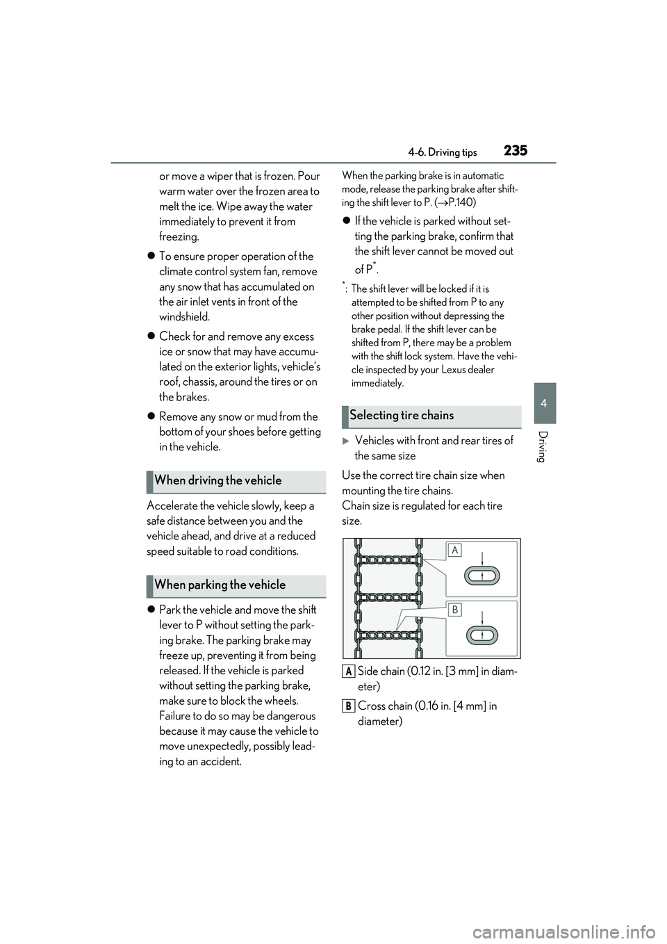
Vehicles with front and rear tires of
the same size
Use the correct tire chain size when
mounting the tire chains.
Chain size is regulated for each tire
size.
Side chain (0.12 in. [3 mm] in diam-
eter)
Cross chain (0.16 in. [4 mm] in
diameter)
When driving the vehicle
When parking the vehicle
Selecting tire chains
A
B
Page 238 of 440
2364-6. Driving tips
Vehicles with front and rear tires of
differing sizes
Tire chains cannot be mounted.
Snow tires should be used instead.
Regulations regarding the use of tire
chains vary depending on location and
type of road. Always check local regu-
lations before installing chains.
■Tire chain installation
Observe the following precautions when
installing and removing chains:
●Install and remove tire chains in a safe
location.
●Install tire chains on the rear tires. Do not
install tire chains on the front tires.
●Install tire chains on rear tires as tightly as
possible. Retighten chains after driving
1/41/2 mile (0.5 1.0 km).
●Install tire chains following the instruc-
tions provided with the tire chains.
Regulations on the use of tire
chains
NOTICE
■Fitting tire chains (vehicles with front
and rear tires of the same size)
The tire pressure warning valves and
transmitters may not function correctly
when tire chains are fitted.
Page 266 of 440
2645-5. Using the other interior features
■Before programming HomeLink®
During programming, it is possible
that garage doors, gates, or other
devices may operate. For this rea-
son, make sure that people and
objects are clear of the garage door
or other devices to prevent injury or
other potential harm.
It is recommended that a new bat-
tery be placed in the remote control
transmitter for more accurate pro-
gramming.
Garage door opener motors manu-
factured after 1995 may be
equipped with rolling code protec-
tion. If this is the case, you may need
a stepladder or other sturdy, safe
device to reach the “Learn” or
“Smart” button on the garage door
opener motor.
■Programming HomeLink®
Steps 1 through 3 must be performed
within 60 seconds, otherwise the indi-
cator light will stop flashing and pro-
gramming will not be able to be
completed.
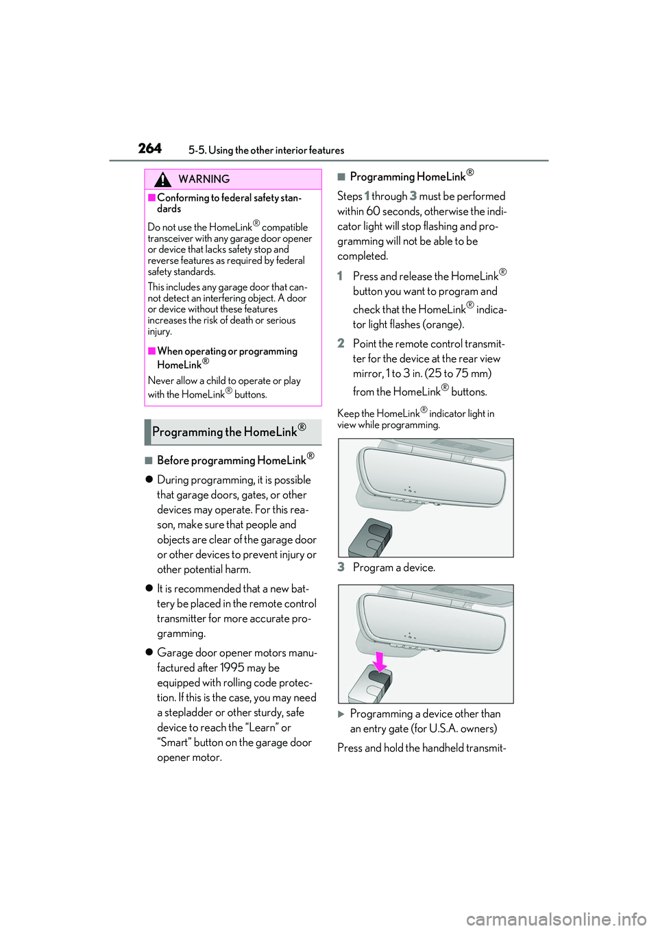
1 Press and release the HomeLink
®
button you want to program and
check that the HomeLink
® indica-
tor light flashes (orange).
2 Point the remote control transmit-
ter for the device at the rear view
mirror, 1 to 3 in. (25 to 75 mm)
from the HomeLink
® buttons.
Keep the HomeLink® indicator light in
view while programming.
3 Program a device.
Programming a device other than
an entry gate (for U.S.A. owners)
Press and hold the handheld transmit-
WARNING
■Conforming to federal safety stan-
dards
Do not use the HomeLink
® compatible
transceiver with any garage door opener
or device that lacks safety stop and
reverse features as required by federal
safety standards.
This includes any ga rage door that can-
not detect an interfering object. A door
or device without these features
increases the risk of death or serious
injury.
■When operating or programming
HomeLink®
Never allow a child to operate or play
with the HomeLink® buttons.
Programming the HomeLink®
Page 268 of 440

2665-5. Using the other interior features
it. Repeat this sequence
(press/hold/release) up to 3 times
to complete programming.
If the garage door opener motor
operates when the HomeLink
®
button is pressed, the garage door
opener motor recognizes the
HomeLink
® signal.
■Enabling 2-way communication
with a garage door (only available
for compatible devices)
When enabled, 2-way communication
allows you to check the status of the
opening and closing of a garage door
through indicators in your vehicle.
2-way communication is only available
if the garage door opener motor used
is a compatible device. (To check
device compatibility, refer to
www.homelink.com.)
1 Within 5 seconds after program-
ming the garage door opener has
been completed, if the garage door
opener motor is trained to
HomeLink
®, both garage door
operation indicators will flash rap-
idly (green) and the light on the
garage door opener motor will
blink twice, indicating that 2-way
communication is enabled.
If the indicators do not flash, perform 2 and
3 within the first 10 presses of the
HomeLink
® button after programming
has been completed.
2 Press a programmed HomeLink®
button to operate a garage door.
3 Within 1 minute of pressing the
HomeLink
® button, after the
garage door operation has
stopped, press the “Learn” or
“Smart” button on the garage door
opener motor. Within 5 seconds of
the establishment of 2-way com-
munication with the garage door
opener, both garage door opera-
tion indicators in the vehicle will
flash rapidly (green) and the light
on the garage door opener motor
will blink twice, indicating that
2-way communication is enabled.
■Reprogramming a single
HomeLink
® button
When the following procedure is per-
formed, buttons which already have
devices registered to them can be
overwritten:
1 With one hand, press and hold the
desired HomeLink
® button.
2 When the HomeLink
® indicator
starts flashing (orange), continue to
hold the HomeLink
® button and
perform “Programming
HomeLink
®” 1 (it takes 20 seconds
for the HomeLink
® indicator to
start flashing).
■Before programming
●Install a new battery in the transmitter.
Page 269 of 440
2675-5. Using the other interior features
5
Interior features
●The battery side of the transmitter must
be pointed away from the HomeLink®.
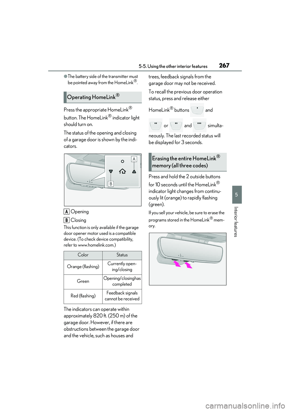
Press the appropriate HomeLink®
button. The HomeLink
® indicator light
should turn on.
The status of the opening and closing
of a garage door is shown by the indi-
cators.
Opening
Closing
This function is only available if the garage
door opener motor used is a compatible
device. (To check device compatibility,
refer to www.homelink.com.)
The indicators can operate within
approximately 820 ft. (250 m) of the
garage door. However, if there are
obstructions between the garage door
and the vehicle, such as houses and trees, feedback signals from the
garage door may not be received.
To recall the previous door operation
status, press and release either
HomeLink
® buttons and
or and simulta-
neously. The last recorded status will
be displayed for 3 seconds.
Press and hold the 2 outside buttons
for 10 seconds until the HomeLink
®
indicator light changes from continu-
ously lit (orange) to rapidly flashing
(green).
If you sell your vehicle, be sure to erase the
programs stored in the HomeLink
® mem-
ory.
Operating HomeLink®
ColorStatus
Orange (flashing)Currently open- ing/closing
GreenOpening/closing has completed
Red (flashing)Feedback signals
cannot be received
A
B
Erasing the entire HomeLink®
memory (all three codes)
Page 271 of 440

269
6
6
Maintenance and care
Maintenance and care
.6-1. Maintenance and careCleaning and protecting the vehi-cle exterior ................................ 270
Cleaning and protecting the vehi- cle interior ................................. 274
6-2. Maintenance Maintenance requirements........................................................ 278
General maintenance ............. 279
Emission inspection and mainte- nance (I/M) programs ......... 282
6-3. Do-it-yourself maintenance Do-it-yourself service precautions........................................................ 283
Hood............................................... 285
Positioning a floor jack............ 285
Engine compartment............... 287
Tires ................................................ 296
Tire inflation pressure.............. 304
Wheels........................................... 305
Air conditioning filter...............307
Electronic key battery ............. 308
Checking and replacing fuses ......................................................... 310
Headlight aim............................... 312
Light bulbs ..................................... 313