Control actuator LEXUS LS430 2003 Factory Repair Manual
[x] Cancel search | Manufacturer: LEXUS, Model Year: 2003, Model line: LS430, Model: LEXUS LS430 2003Pages: 4500, PDF Size: 87.45 MB
Page 3 of 4500
When there is a malfunction in the contact point of the terminals or installation problems with parts,
removal and installation of the suspected problem parts may return the system to the normal condition
either completely or temporarily.
In order to determine the malfunctioning area, be sure to check the conditions at the time the malfunction
occurred, such as by DTC output and the freeze frame data output, and record it before disconnecting
each connector or removing and installing parts.
Since the ABS with EBD & BA & TRAC & VSC systems may be influenced by a malfunction in the
other systems, be sure to check for DTCs in the other systems.
Be sure to remove and install the skid control ECU, ABS & TRAC actuator and each sensor with the IG
switch OFF unless specified in the inspection procedure.
When removing and installing the skid control ECU, ABS & TRAC actuator and each sensor, be sure to
check that the normal display is output in test mode inspection and in DTC output inspection after
installing all the parts.
After replacing the yaw rate sensor and/or the brake actuator assembly, make sure to perform yaw rate
sensor and deceleration sensor zero point calibration.
(see CALIBRATION
)
CAN communication system is used for the data communication between the skid control ECU (included
in the actuator), the steering angle sensor, and the yaw rate sensor (the deceleration sensor is included). If
there is trouble in the CAN communication line, the DTC in the communication line is output.
If the DTC in the CAN communication line is output, repair the malfunction in the communication line
and troubleshoot the ABS with EBD & BA & TRAC & VSC systems under the condition that data
communication is normal.
Since the CAN communication line has its own length and route, it can not be repaired temporarily with
the bypass wire, etc.
SYSTEM NAME REFERENCE
System NameSee Procedure
Front Power Seat Control SystemINITIALIZATION
Page 7 of 4500
1.SYSTEM DESCRIPTION
HINT:
The skid control ECU is a single unit with ABS & TRACTION ACTUATOR.
The skid control ECU also works as a TPMS (Tire Pressure Monitor System) ECU.
The yaw rate sensor and deceleration sensor are combined and in a single unit. This unit
communicates with the skid control ECU through CAN communication.
a. ABS (Anti-lock Brake System)
The ABS helps prevent the wheels from locking when the brakes are applied firmly or when
braking on a slippery surface.
ECUSystem
ECMSkid Control ECUShift Position SignalCAN Communication
System
ECMSkid Control ECUThrottle Position SignalCAN Communication
System
ECMSkid Control ECUEngine Revolution SignalCAN Communication
System
ECMSkid Control ECUWater Temperature Sensor
SignalCAN Communication
System
ECMSkid Control ECUIntake Air Temperature Sensor
SignalCAN Communication
System
Skid Control ECUECMYaw Rate (Deceleration) SignalCAN Communication
System
Skid Control ECUECMVSC Data SignalCAN Communication
System
Skid Control ECUGate Way ECUBrake Warning Lamp ON
SignalBEAN System
Skid Control ECUGate Way ECUABS Warning Lamp ON SignalBEAN System
Skid Control ECUGate Way ECUTRAC OFF Indicator ON
SignalBEAN System
Skid Control ECUGate Way ECUSlip Indicator ON SignalBEAN System
Skid Control ECUGate Way ECUMulti Information display
SignalBEAN System
Page 8 of 4500
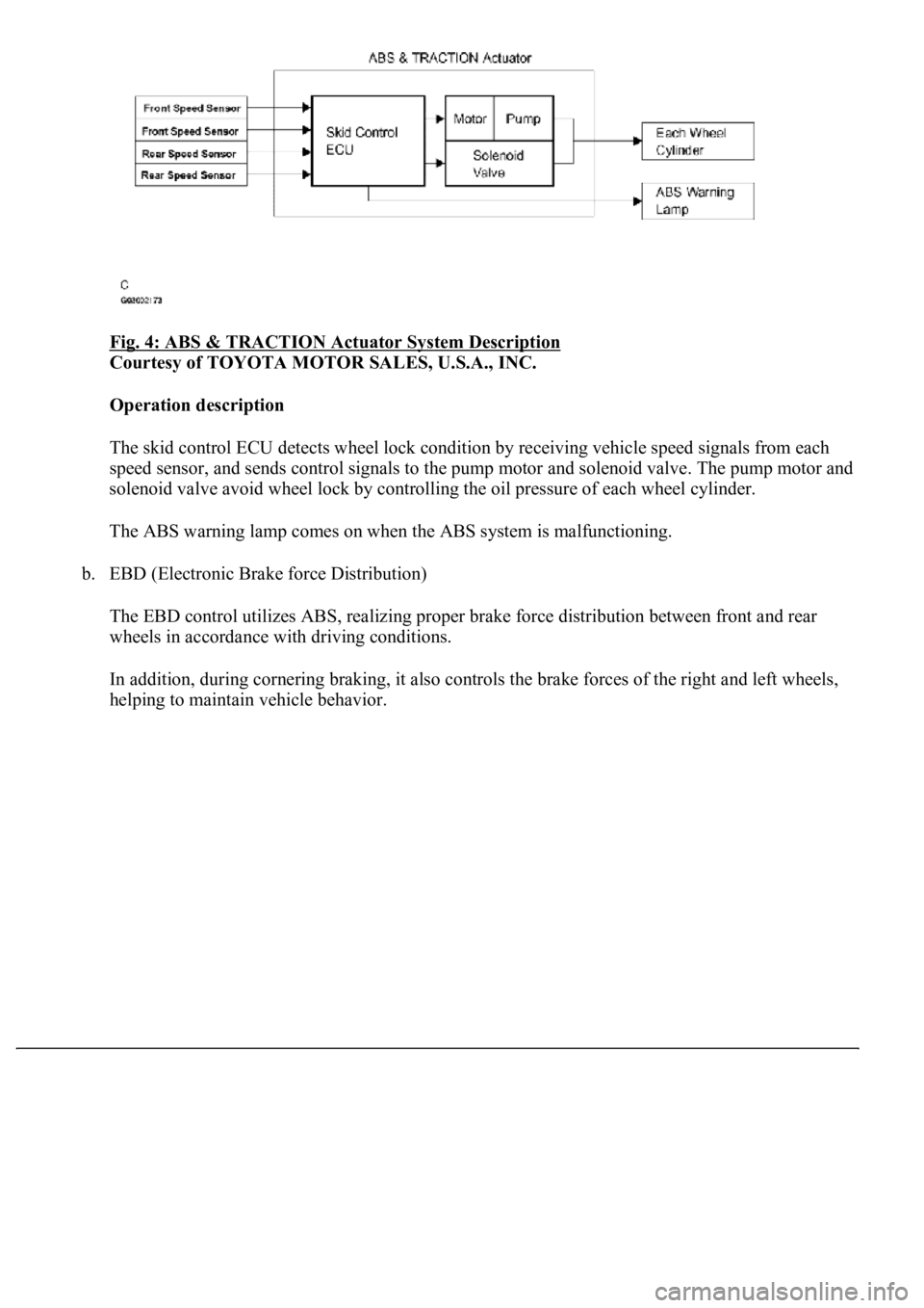
Fig. 4: ABS & TRACTION Actuator System Description
Courtesy of TOYOTA MOTOR SALES, U.S.A., INC.
Operation description
The skid control ECU detects wheel lock condition by receiving vehicle speed signals from each
<005600530048004800470003005600480051005600520055000f00030044005100470003005600480051004700560003004600520051005700550052004f00030056004c004a00510044004f005600030057005200030057004b0048000300530058005000
53000300500052005700520055000300440051004700030056[olenoid valve. The pump motor and
solenoid valve avoid wheel lock by controlling the oil pressure of each wheel cylinder.
The ABS warning lamp comes on when the ABS system is malfunctioning.
b. EBD (Electronic Brake force Distribution)
The EBD control utilizes ABS, realizing proper brake force distribution between front and rear
wheels in accordance with driving conditions.
In addition, during cornering braking, it also controls the brake forces of the right and left wheels,
helping to maintain vehicle behavior.
Page 9 of 4500
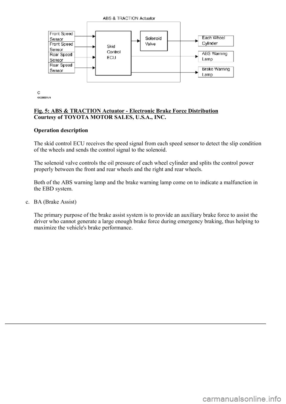
Fig. 5: ABS & TRACTION Actuator - Electronic Brake Force Distribution
Courtesy of TOYOTA MOTOR SALES, U.S.A., INC.
Operation description
The skid control ECU receives the speed signal from each speed sensor to detect the slip condition
<0052004900030057004b00480003005a004b00480048004f0056000300440051004700030056004800510047005600030057004b00480003004600520051005700550052004f00030056004c004a00510044004f00030057005200030057004b0048000300
560052004f004800510052004c004700110003[
The solenoid valve controls the oil pressure of each wheel cylinder and splits the control power
properly between the front and rear wheels and the right and rear wheels.
Both of the ABS warning lamp and the brake warning lamp come on to indicate a malfunction in
the EBD system.
c. BA (Brake Assist)
The primary purpose of the brake assist system is to provide an auxiliary brake force to assist the
driver who cannot generate a large enough brake force during emergency braking, thus helping to
maximize the vehicle's brake performance.
Page 10 of 4500
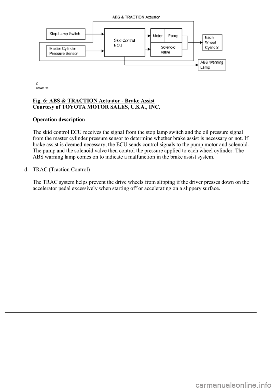
Fig. 6: ABS & TRACTION Actuator - Brake Assist
Courtesy of TOYOTA MOTOR SALES, U.S.A., INC.
Operation description
The skid control ECU receives the signal from the stop lamp switch and the oil pressure signal
from the master cylinder pressure sensor to determine whether brake assist is necessary or not. If
brake assist is deemed necessary, the ECU sends control signals to the pump motor and solenoid.
The pump and the solenoid valve then control the pressure applied to each wheel cylinder. The
ABS warning lamp comes on to indicate a malfunction in the brake assist system.
d. TRAC (Traction Control)
The TRAC system helps prevent the drive wheels from slipping if the driver presses down on the
accelerator pedal excessivel
y when starting off or accelerating on a slippery surface.
Page 11 of 4500
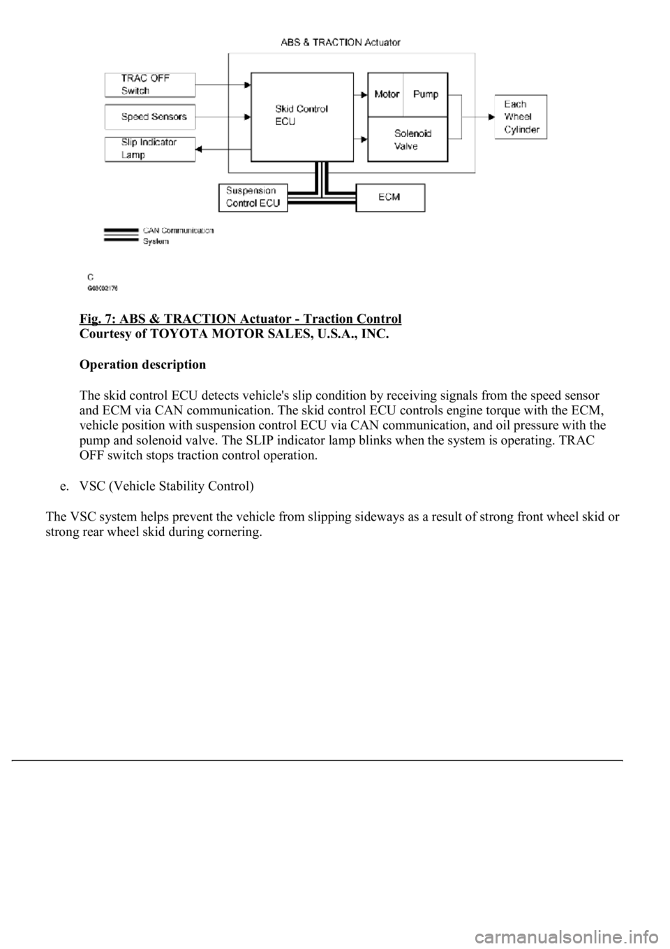
Fig. 7: ABS & TRACTION Actuator - Traction Control
Courtesy of TOYOTA MOTOR SALES, U.S.A., INC.
Operation description
The skid control ECU detects vehicle's slip condition by receiving signals from the speed sensor
<004400510047000300280026003000030059004c004400030026002400310003004600520050005000580051004c004600440057004c00520051001100030037004b004800030056004e004c00470003004600520051005700550052004f00030028002600
380003004600520051005700550052004f0056000300480051[gine torque with the ECM,
vehicle position with suspension control ECU via CAN communication, and oil pressure with the
pump and solenoid valve. The SLIP indicator lamp blinks when the system is operating. TRAC
OFF switch stops traction control operation.
e. VSC (Vehicle Stability Control)
The VSC system helps prevent the vehicle from slipping sideways as a result of strong front wheel skid or
stron
g rear wheel skid during cornering.
Page 12 of 4500
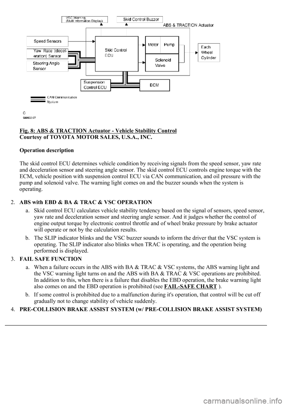
Fig. 8: ABS & TRACTION Actuator - Vehicle Stability Control
Courtesy of TOYOTA MOTOR SALES, U.S.A., INC.
Operation description
The skid control ECU determines vehicle condition by receiving signals from the speed sensor, yaw rate
and deceleration sensor and steering angle sensor. The skid control ECU controls engine torque with the
ECM, vehicle position with suspension control ECU via CAN communication, and oil pressure with the
pump and solenoid valve. The warning light comes on and the buzzer sounds when the system is
operating.
2.ABS with EBD & BA & TRAC & VSC OPERATION
a. Skid control ECU calculates vehicle stability tendency based on the signal of sensors, speed sensor,
yaw rate and deceleration sensor and steering angle sensor. And it judges whether the control of
engine output torque by electronic control throttle and of wheel brake pressure by brake actuator
will operate or not by the calculation results.
b. The SLIP indicator blinks and the VSC buzzer sounds to inform the driver that the VSC system is
operating. The SLIP indicator also blinks when TRAC is operating, and the operation being
performed is displayed.
3.FAIL SAFE FUNCTION
a. When a failure occurs in the ABS with BA & TRAC & VSC systems, the ABS warning light and
the VSC warning light turns on and the ABS with BA & TRAC & VSC operations are prohibited.
In addition to this, when there is a failure that disables the EBD operation, the brake warning light
also comes on and the EBD operation is prohibited (see FAIL
-SAFE CHART ).
b. If some control is prohibited due to a malfunction during it's operation, that control will be cut off
gradually not to change stability of vehicle suddenly.
4.PRE-COLLISION BRAKE ASSIST SYSTEM (w/ PRE-COLLISION BRAKE ASSIST SYSTEM)
Page 83 of 4500
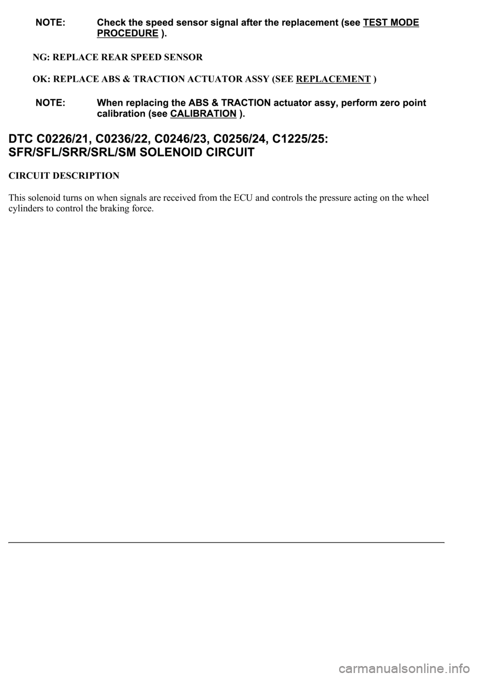
NG: REPLACE REAR SPEED SENSOR
OK: REPLACE ABS & TRACTION ACTUATOR ASSY (SEE REPLACEMENT
)
CIRCUIT DESCRIPTION
<0037004b004c0056000300560052004f004800510052004c00470003005700580055005100560003005200510003005a004b0048005100030056004c004a00510044004f0056000300440055004800030055004800460048004c0059004800470003004900
550052005000030057004b0048000300280026003800030044[nd controls the pressure acting on the wheel
c
ylinders to control the braking force.
Page 86 of 4500
OK: Go to next step
The same DTC is recorded.
NG: PROCEED TO NEXT CIRCUIT INSPECTION SHOWN IN PROBLEM SYMPTOMS
TABLE
OK: REPLACE ABS & TRACTION ACTUATOR ASSY (SEE REPLACEMENT
)
CIRCUIT DESCRIPTION
The ABS motor relays consist of 2 relays are included in the engine room No.3 R/B.
The ABS cut relay is turned on after turning the ignition switch to the ON position. If the DTCs in the
ABS pump motor circuit are memorized, the ABS cut relay cuts off the power supply to the ABS motor
relay and performs the fail safe.
While any of the ABS, BA, TRAC and VSC is operating, the skid control ECU (included in the actuator)
<0057005800550051005600030057004b00480003002400250036000300500052005700520055000300550048004f0044005c0003005200510003005700520003005200530048005500440057004800030057004b0048000300440046005700580044005700
52005500030053005800500053000300500052005700520055[.
If the voltage applied to the ABS motor relays (+BM) drops below the condition that detects the DTCs
due to the shorta
ge of the battery or alternator output, the DTCs may be memorized.
Page 97 of 4500
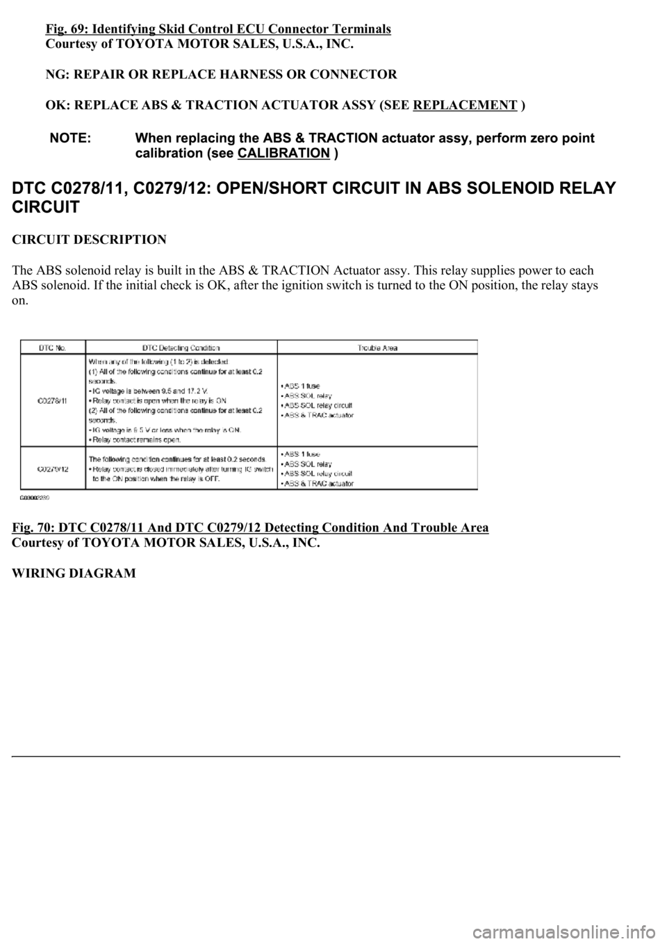
Fig. 69: Identifying Skid Control ECU Connector Terminals
Courtesy of TOYOTA MOTOR SALES, U.S.A., INC.
NG: REPAIR OR REPLACE HARNESS OR CONNECTOR
OK: REPLACE ABS & TRACTION ACTUATOR ASSY (SEE REPLACEMENT
)
CIRCUIT DESCRIPTION
The ABS solenoid relay is built in the ABS & TRACTION Actuator assy. This relay supplies power to each
ABS solenoid. If the initial check is OK, after the ignition switch is turned to the ON position, the relay stays
on.
Fig. 70: DTC C0278/11 And DTC C0279/12 Detecting Condition And Trouble Area
Courtesy of TOYOTA MOTOR SALES, U.S.A., INC.
WIRING DIAGRAM