LEXUS LS430 2003 Factory Owners Manual
LS430 2003
LEXUS
LEXUS
https://www.carmanualsonline.info/img/36/57050/w960_57050-0.png
LEXUS LS430 2003 Factory Owners Manual
Page 630 of 4500
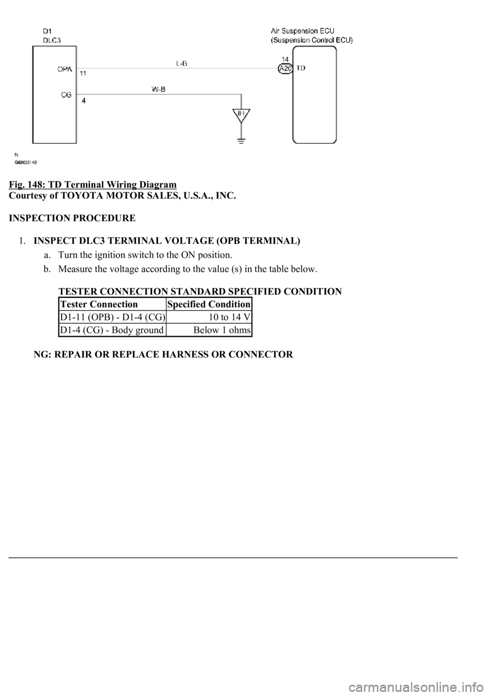
Fig. 148: TD Terminal Wiring Diagram
Courtesy of TOYOTA MOTOR SALES, U.S.A., INC.
INSPECTION PROCEDURE
1.INSPECT DLC3 TERMINAL VOLTAGE (OPB TERMINAL)
a. Turn the ignition switch to the ON position.
b. Measure the voltage according to the value (s) in the table below.
TESTER CONNECTION STANDARD SPECIFIED CONDITION
NG: REPAIR OR REPLACE HARNESS OR CONNECTOR
Tester ConnectionSpecified Condition
D1-11 (OPB) - D1-4 (CG)10 to 14 V
D1-4 (CG) - Body groundBelow 1 ohms
Page 758 of 4500
Courtesy of TOYOTA MOTOR SALES, U.S.A., INC.
CIRCUIT DESCRIPTION
This circuit provides the power to the radio receiver assy.
WIRING DIAGRAM
Fig. 43: Identifying Power Source Circuit (Radio Receiver Assy) Wiring Diagram
Courtesy of TOYOTA MOTOR SALES, U.S.A., INC.
INSPECTION PROCEDURE
1.INSPECT RADIO RECEIVER ASSY (+B, ACC, GND)
Page 760 of 4500
Fig. 44: Disconnecting Radio Receiver Assy Connector R2
Courtesy of TOYOTA MOTOR SALES, U.S.A., INC.
CIRCUIT DESCRIPTION
This circuit provides the power to the stereo component tuner.
WIRING DIAGRAM
Page 761 of 4500
Fig. 45: Identifying Power Source Circuit (Stereo Component Tuner) Wiring Diagram
Courtesy of TOYOTA MOTOR SALES, U.S.A., INC.
INSPECTION PROCEDURE
1.INSPECT STEREO COMPONENT TUNER (B, ACC, GND)
a. Disconnect the stereo component tuner connector S31.
b. Measure the resistance according to the value (s) in the table below.
Standard:
TESTER CONNECTION CONDITION CHART
Tester connectionConditionSpecified condition
GND - Body groundAlwaysBelow 1 ohms
Page 763 of 4500
WIRING DIAGRAM
Fig. 47: Stereo Component Amplifier Assy Wiring Diagram
Courtesy of TOYOTA MOTOR SALES, U.S.A., INC.
INSPECTION PROCEDURE
1.INSPECT STEREO COMPONENT AMPLIFIER ASSY (+B, +B2, ACC, GND, E)
a. Disconnect the stereo component amplifier assy connector S29, S30.
b. Measure the resistance according to the value (s) in the table below.
TESTER CONNECTION CONDITION CHART
Tester connectionConditionSpecified condition
GND - Body groundAlwaysBelow 1 ohms
E - Body groundAlwaysBelow 1 ohms
Page 765 of 4500
Fig. 49: Identifying Standard Model
Courtesy of TOYOTA MOTOR SALES, U.S.A., INC.
CIRCUIT DESCRIPTION
This circuit provides the power to the audio and rear A/C control switch.
WIRING DIAGRAM
Page 766 of 4500
Fig. 50: Identifying Audio And Rear A/C Control SW Wiring Diagram
Courtesy of TOYOTA MOTOR SALES, U.S.A., INC.
INSPECTION PROCEDURE
1.INSPECT AUDIO AND REAR A/C CONTROL SWITCH (+B, ACC, GND)
a. Disconnect the audio and rear A/C control switch connector A35.
b. Measure the resistance according to the value (s) in the table below.
TESTER CONNECTION CONDITION CHART
c. Measure the voltage according to the value (s) in the table below.
TESTER CONNECTION CONDITION CHART
Tester connectionConditionSpecified condition
GND - Body groundAlwaysBelow 1 ohms
Tester connectionConditionSpecified condition
+B - GNDAlways10 to 14V
Page 768 of 4500
If there is a short in this circuit, the stereo component amplifier assy detects it and stops output to the speakers.
Thus sound can not be heard from the speaker even if there is no malfunction in the stereo component amplifier
assy or speaker.
Standard System:
There are two circuits that detect a short circuit.
When a short in the woofer speaker circuit is detected, sound output from only the woofer speaker circuit
stops.
When a short in the other circuits is detected, sound output from the circuits other than the woofer
speaker circuit is stopped.
Mark Levinson System:
When a short in the speaker circuit is detected, all sound output is stopped.
WIRING DIAGRAM
Page 769 of 4500
Fig. 52: Speaker Circuit Wiring Diagram (1 Of 2)
Courtesy of TOYOTA MOTOR SALES, U.S.A., INC.
Fig. 53: Speaker Circuit Wiring Diagram (2 Of 2)
Courtesy of TOYOTA MOTOR SALES, U.S.A., INC.
INSPECTION PROCEDURE
1.CHECK HARNESS AND CONNECTOR (STEREO COMPONENT AMPLIFIER ASSY -
SPEAKER ASSY)
Page 777 of 4500
Fig. 59: Measuring Resistance Between Terminals Of Speaker
Courtesy of TOYOTA MOTOR SALES, U.S.A., INC.
OK: PROCEED TO NEXT CIRCUIT INSPECTION SHOWN ON PROBLEM SYMPTOMS
TABLE
CIRCUIT DESCRIPTION
The radio receiver assy sends a sound signal to the stereo component amplifier assy through this circuit. The
sound signal that has been sent is amplified by the stereo component amplifier assy, and then is sent to the
<0056005300480044004e0048005500110003002c004900030057004b0048005500480003004c00560003004400510003005200530048005100030052005500030056004b0052005500570003004c005100030057004b004800030046004c00550046005800
4c0057000f0003005600520058005100470003004600440051[<00030051005200570003004500480003004b00480044005500470003004900550052005000030057004b004800030056005300480044004e00480055000300480059004800510003004c004900030057004b0048005500480003004c005600030051005200
03[
malfunction in the stereo component amplifier assy or speaker.
WIRING DIAGRAM