wiring diagram LEXUS LS430 2003 Factory Repair Manual
[x] Cancel search | Manufacturer: LEXUS, Model Year: 2003, Model line: LS430, Model: LEXUS LS430 2003Pages: 4500, PDF Size: 87.45 MB
Page 778 of 4500
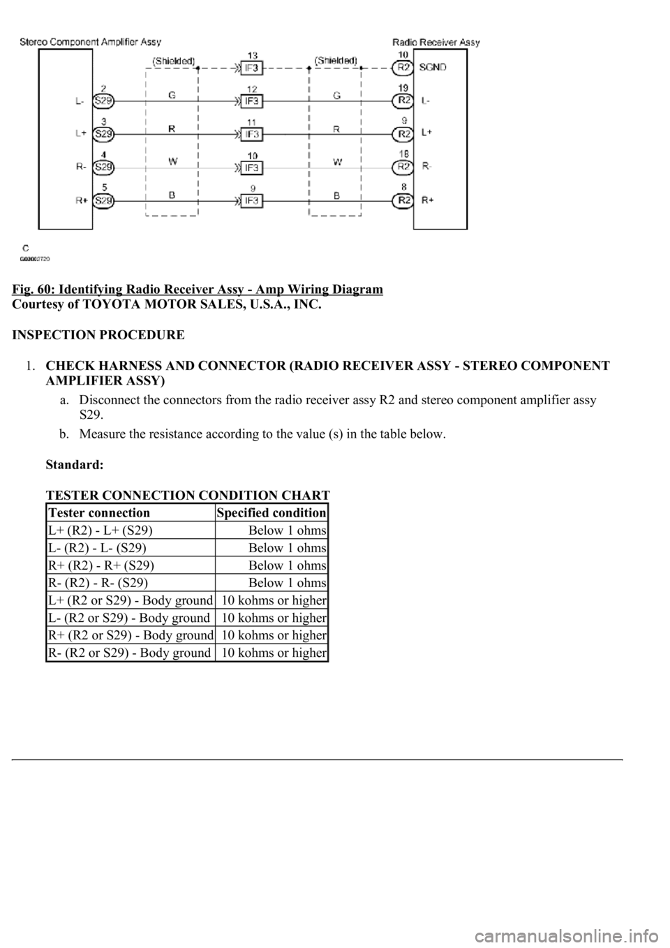
Fig. 60: Identifying Radio Receiver Assy - Amp Wiring Diagram
Courtesy of TOYOTA MOTOR SALES, U.S.A., INC.
INSPECTION PROCEDURE
1.CHECK HARNESS AND CONNECTOR (RADIO RECEIVER ASSY - STEREO COMPONENT
AMPLIFIER ASSY)
a. Disconnect the connectors from the radio receiver assy R2 and stereo component amplifier assy
S29.
b. Measure the resistance according to the value (s) in the table below.
Standard:
TESTER CONNECTION CONDITION CHART
Tester connectionSpecified condition
L+ (R2) - L+ (S29)Below 1 ohms
L- (R2) - L- (S29)Below 1 ohms
R+ (R2) - R+ (S29)Below 1 ohms
R- (R2) - R- (S29)Below 1 ohms
L+ (R2 or S29) - Body ground10 kohms or higher
L- (R2 or S29) - Body ground10 kohms or higher
R+ (R2 or S29) - Body ground10 kohms or higher
R- (R2 or S29) - Body ground10 kohms or higher
Page 781 of 4500
Fig. 63: Identifying Stereo Components Amplifier
Courtesy of TOYOTA MOTOR SALES, U.S.A., INC.
NG: REPAIR OR REPLACE HARNESS OR CONNECTOR
OK: PROCEED TO NEXT CIRCUIT INSPECTION SHOWN ON PROBLEM SYMPTOMS
TABLE
CIRCUIT DESCRIPTION
The stereo component tuner sends a sound signal to the radio receiver assy through this circuit.
WIRING DIAGRAM
Page 782 of 4500
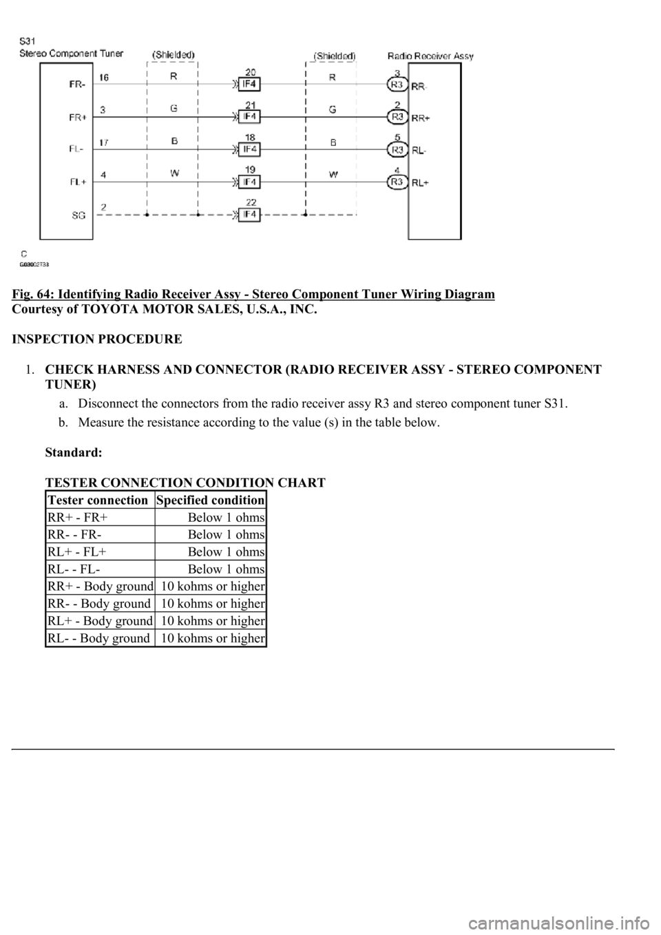
Fig. 64: Identifying Radio Receiver Assy - Stereo Component Tuner Wiring Diagram
Courtesy of TOYOTA MOTOR SALES, U.S.A., INC.
INSPECTION PROCEDURE
1.CHECK HARNESS AND CONNECTOR (RADIO RECEIVER ASSY - STEREO COMPONENT
TUNER)
a. Disconnect the connectors from the radio receiver assy R3 and stereo component tuner S31.
b. Measure the resistance according to the value (s) in the table below.
Standard:
TESTER CONNECTION CONDITION CHART
Tester connectionSpecified condition
RR+ - FR+Below 1 ohms
RR- - FR-Below 1 ohms
RL+ - FL+Below 1 ohms
RL- - FL-Below 1 ohms
RR+ - Body ground10 kohms or higher
RR- - Body ground10 kohms or higher
RL+ - Body ground10 kohms or higher
RL- - Body ground10 kohms or higher
Page 785 of 4500
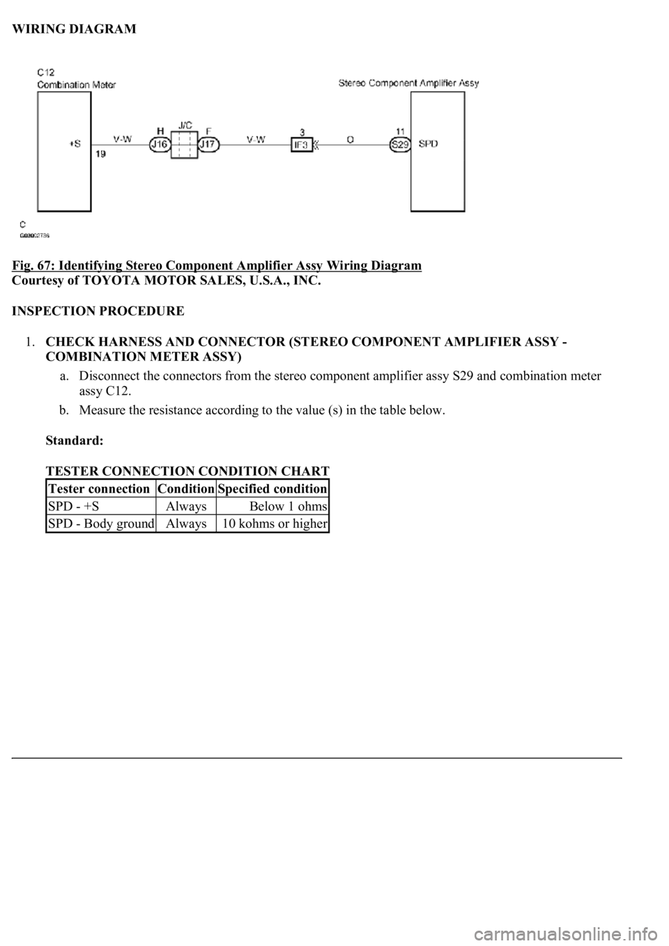
WIRING DIAGRAM
Fig. 67: Identifying Stereo Component Amplifier Assy Wiring Diagram
Courtesy of TOYOTA MOTOR SALES, U.S.A., INC.
INSPECTION PROCEDURE
1.CHECK HARNESS AND CONNECTOR (STEREO COMPONENT AMPLIFIER ASSY -
COMBINATION METER ASSY)
a. Disconnect the connectors from the stereo component amplifier assy S29 and combination meter
assy C12.
b. Measure the resistance according to the value (s) in the table below.
Standard:
TESTER CONNECTION CONDITION CHART
Tester connectionConditionSpecified condition
SPD - +SAlwaysBelow 1 ohms
SPD - Body groundAlways10 kohms or higher
Page 790 of 4500
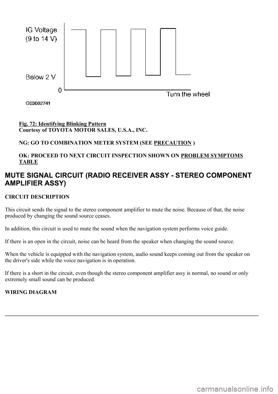
Fig. 72: Identifying Blinking Pattern
Courtesy of TOYOTA MOTOR SALES, U.S.A., INC.
NG: GO TO COMBINATION METER SYSTEM (SEE PRECAUTION
)
OK: PROCEED TO NEXT CIRCUIT INSPECTION SHOWN ON PROBLEM SYMPTOMS
TABLE
CIRCUIT DESCRIPTION
This circuit sends the signal to the stereo component amplifier to mute the noise. Because of that, the noise
produced by changing the sound source ceases.
In addition, this circuit is used to mute the sound when the navigation system performs voice guide.
If there is an open in the circuit, noise can be heard from the speaker when changing the sound source.
When the vehicle is equipped with the navigation system, audio sound keeps coming out from the speaker on
the driver's side while the voice navigation is in operation.
If there is a short in the circuit, even though the stereo component amplifier assy is normal, no sound or only
extremely small sound can be produced.
WIRING DIAGRAM
Page 791 of 4500
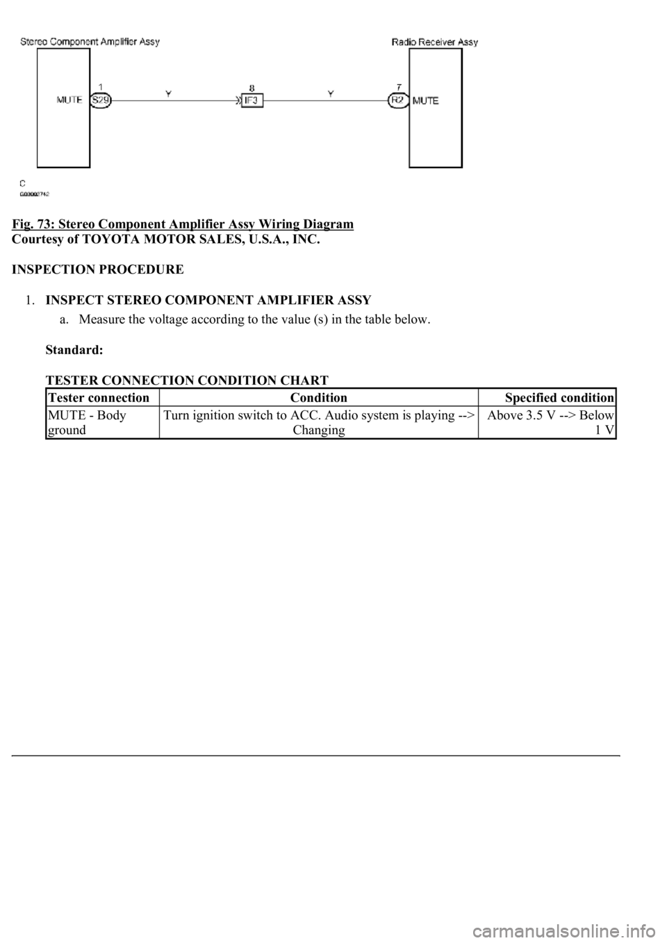
Fig. 73: Stereo Component Amplifier Assy Wiring Diagram
Courtesy of TOYOTA MOTOR SALES, U.S.A., INC.
INSPECTION PROCEDURE
1.INSPECT STEREO COMPONENT AMPLIFIER ASSY
a. Measure the voltage according to the value (s) in the table below.
Standard:
TESTER CONNECTION CONDITION CHART
Tester connectionConditionSpecified condition
MUTE - Body
groundTurn ignition switch to ACC. Audio system is playing -->
ChangingAbove 3.5 V --> Below
1 V
Page 797 of 4500
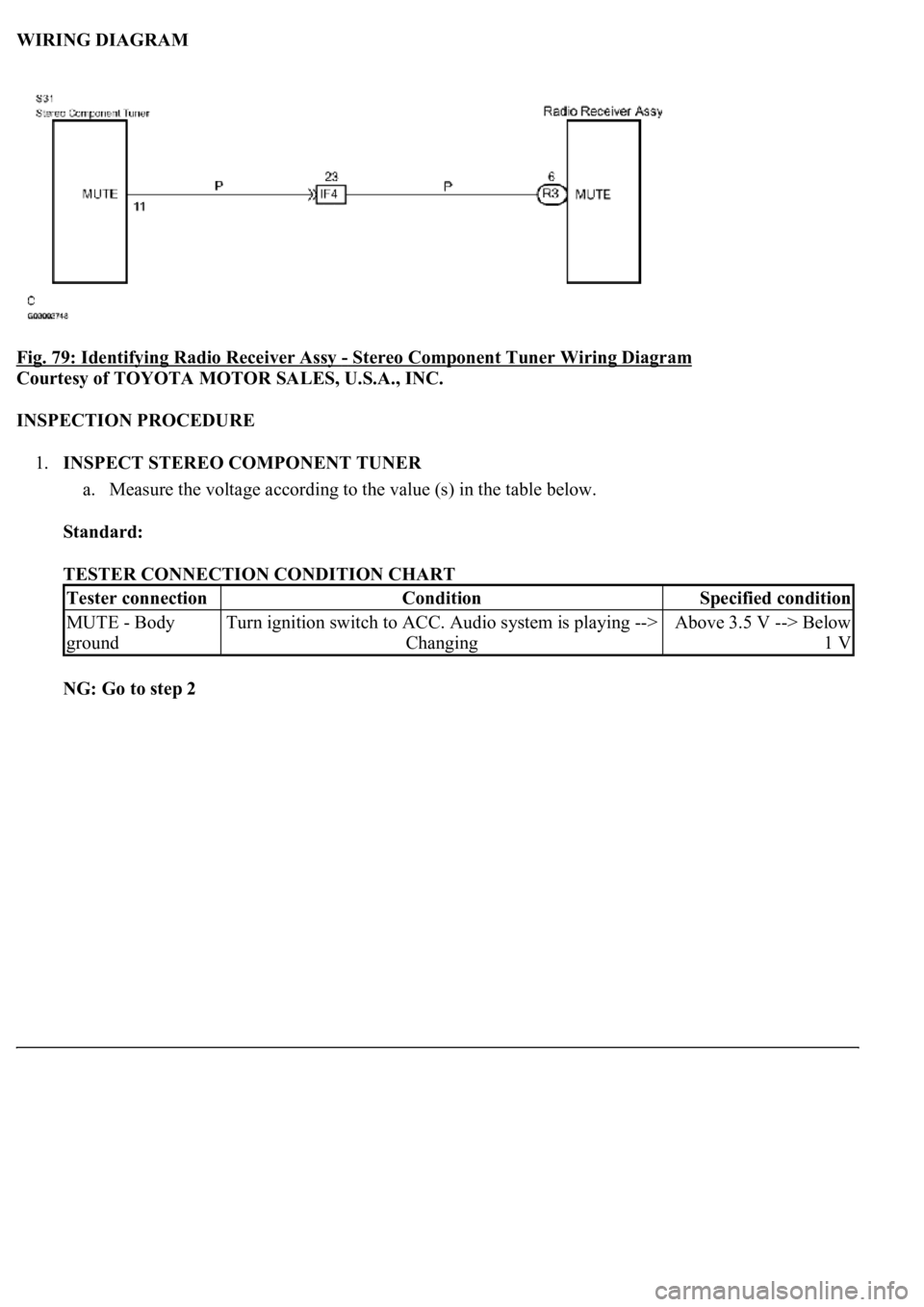
WIRING DIAGRAM
Fig. 79: Identifying Radio Receiver Assy
- Stereo Component Tuner Wiring Diagram
Courtesy of TOYOTA MOTOR SALES, U.S.A., INC.
INSPECTION PROCEDURE
1.INSPECT STEREO COMPONENT TUNER
a. Measure the voltage according to the value (s) in the table below.
Standard:
TESTER CONNECTION CONDITION CHART
NG: Go to step 2
Tester connectionConditionSpecified condition
MUTE - Body
groundTurn ignition switch to ACC. Audio system is playing -->
ChangingAbove 3.5 V --> Below
1 V
Page 801 of 4500
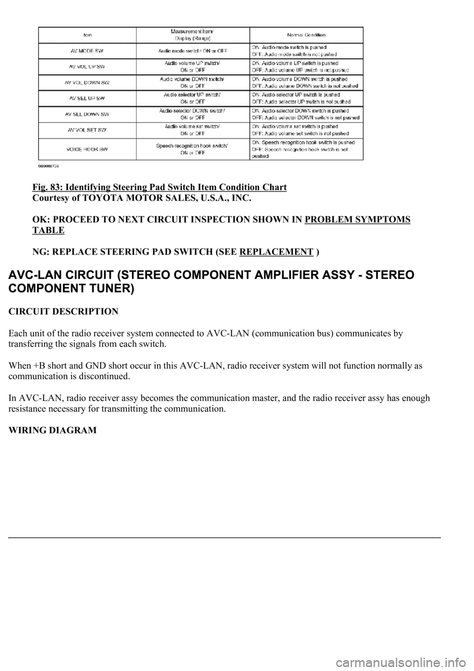
Fig. 83: Identifying Steering Pad Switch Item Condition Chart
Courtesy of TOYOTA MOTOR SALES, U.S.A., INC.
OK: PROCEED TO NEXT CIRCUIT INSPECTION SHOWN IN PROBLEM SYMPTOMS
TABLE
NG: REPLACE STEERING PAD SWITCH (SEE REPLACEMENT
)
CIRCUIT DESCRIPTION
Each unit of the radio receiver system connected to AVC-LAN (communication bus) communicates by
transferring the signals from each switch.
When +B short and GND short occur in this AVC-LAN, radio receiver system will not function normally as
communication is discontinued.
In AVC-LAN, radio receiver assy becomes the communication master, and the radio receiver assy has enough
resistance necessary for transmitting the communication.
WIRING DIAGRAM
Page 802 of 4500
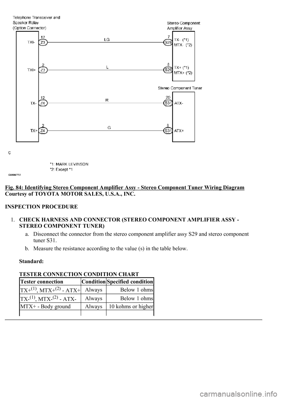
Fig. 84: Identifying Stereo Component Amplifier Assy - Stereo Component Tuner Wiring Diagram
Courtesy of TOYOTA MOTOR SALES, U.S.A., INC.
INSPECTION PROCEDURE
1.CHECK HARNESS AND CONNECTOR (STEREO COMPONENT AMPLIFIER ASSY -
STEREO COMPONENT TUNER)
a. Disconnect the connector from the stereo component amplifier assy S29 and stereo component
tuner S31.
b. Measure the resistance according to the value (s) in the table below.
Standard:
TESTER CONNECTION CONDITION CHART
Tester connectionConditionSpecified condition
TX+(1), MTX+(2) - ATX+AlwaysBelow 1 ohms
TX-(1), MTX-(2) - ATX-AlwaysBelow 1 ohms
MTX+ - Body groundAlways10 kohms or higher
Page 806 of 4500
In AVC-LAN, radio receiver assy becomes the communication master, and the radio receiver assy has enough
resistance necessary for transmitting the communication.
WIRING DIAGRAM
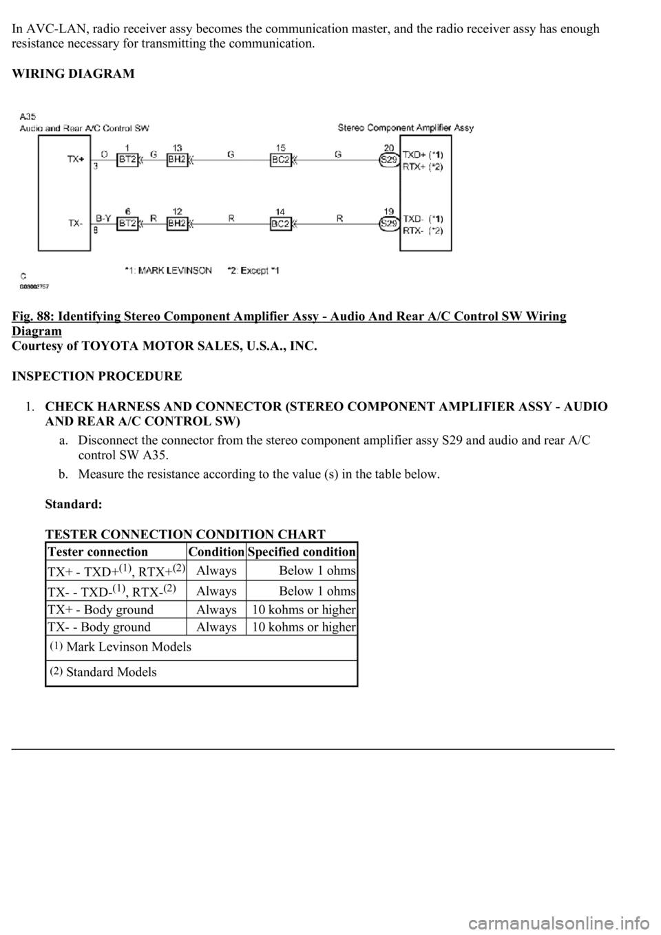
Fig. 88: Identifying Stereo Component Amplifier Assy
- Audio And Rear A/C Control SW Wiring
Diagram
Courtesy of TOYOTA MOTOR SALES, U.S.A., INC.
INSPECTION PROCEDURE
1.CHECK HARNESS AND CONNECTOR (STEREO COMPONENT AMPLIFIER ASSY - AUDIO
AND REAR A/C CONTROL SW)
a. Disconnect the connector from the stereo component amplifier assy S29 and audio and rear A/C
control SW A35.
b. Measure the resistance according to the value (s) in the table below.
Standard:
TESTER CONNECTION CONDITION CHART
Tester connectionConditionSpecified condition
TX+ - TXD+(1), RTX+(2)AlwaysBelow 1 ohms
TX- - TXD-(1), RTX-(2)AlwaysBelow 1 ohms
TX+ - Body groundAlways10 kohms or higher
TX- - Body groundAlways10 kohms or higher
(1)Mark Levinson Models
(2)Standard Models