check engine LEXUS LS430 2003 Factory Repair Manual
[x] Cancel search | Manufacturer: LEXUS, Model Year: 2003, Model line: LS430, Model: LEXUS LS430 2003Pages: 4500, PDF Size: 87.45 MB
Page 4115 of 4500
pressure regulator.
i. Disconnect the hand-held tester from the DLC3.
j. Start the engine.
k. Measure the fuel pressure at idle.
Fuel pressure: 304 to 343 kPa (3.1 to 3.5 kgf/cm2, 44 to 50 psi)
l. Stop the engine.
m. Check that the fuel pressure remains as specified for 5 minutes after the engine has stopped.
Fuel pressure: 147 kPa (1.5 kgf/cm2, 21 psi) or more
If pressure is not as specified, check the fuel pump, pressure regulator and/or injectors.
n. After checking fuel pressure, disconnect the negative (-) terminal cable from the battery and
carefully remove the SST to prevent gasoline from spilling.
SST 09268-45014
o. Reinstall the fuel pressure pulsation damper to the RH delivery pipe (see REPLACEMENT
).
p. Reconnect the negative (-) terminal cable to the battery.
q. Check for fuel leaks.
3.INSPECT FUEL PUMP
Page 4199 of 4500
ON-VEHICLE INSPECTION
1.INSPECT REFRIGERANT VOLUME
a. Check the sight glass on the liquid tube.
Test conditions:
Engine is running at 1,500 rpm
Single A/C:
Blower speed control switch at "HI" position
Dual A/C:
Front blower switch at "HI" position
Rear blower switch at "HI" position
A/C switch ON
Single A/C:
Temperature control switch at "MAX. COOL" position
Dual A/C:
Rear temperature control switch at "MAX. COOL" position
Front driver side temperature control switch at "MAX. COOL" position
Front passenger side temperature control switch at "MAX. COOL" position
Fully open the doors
Page 4227 of 4500

INSPECTION
1.CHECK EVAPORATOR AND HEATER RADIATOR FINS FOR FOREIGN MATTER
If foreign matter is attached to the fin, blow it off with compressed air.
2.CHECK FITTINGS FOR CRACKS OR SCRATCHES
a. Repair as necessary.
3.INSPECT EVAPORATOR TEMPERATURE SENSOR CIRCUIT (See DTC B1413:
EVAPORATOR TEMPERATURE SENSOR CIRCUIT )
4.INSPECT COOL AIR BYPASS DAMPER POSITION SENSOR CIRCUIT (DRIVER SIDE) (See
DTC B1434: MAX COOL DAMPER POSITION SENSOR CIRCUIT (DRIVER SIDE)
)
5.INSPECT COOL AIR BYPASS DAMPER CONTROL SERVOMOTOR CIRCUIT (DRIVER
SIDE) (See COOL AIR BYPASS DAMPER CONTROL SERVOMOTOR CIRCUIT (DRIVER
SIDE) )
6.INSPECT COOL AIR BYPASS DAMPER POSITION SENSOR CIRCUIT (PASSENGER SIDE)
(See COOL AIR BYPASS DAMPER CONTROL SERVOMOTOR CIRCUIT (PASSENGER
SIDE) )
7.INSPECT COOL AIR BYPASS DAMPER CONTROL SERVOMOTOR CIRCUIT (PASSENGER
SIDE) (SEE COOL AIR BYPASS DAMPER CONTROL SERVOMOTOR CIRCUIT
(PASSENGER SIDE) )
8.INSPECT WATER VALVE CONTROL SERVOMOTOR CIRCUIT (See WATER VALVE
CONTROL SERVOMOTOR CIRCUIT )
9.INSPECT AIR VENT MODE DAMPER CONTROL SERVOMOTOR CIRCUIT (See AIR VENT
MODE DAMPER CONTROL SERVOMOTOR CIRCUIT )
10.INSPECT AIR MIX DAMPER CONTROL SERVOMOTOR CIRCUIT (See AIR MIX DAMPER
CONTROL SERVOMOTOR CIRCUIT )
OVERHAUL
HINT:
Installation is in the reverse order of removal.
See COMPONENTS .
1.DISCONNECT NEGATIVE TERMINAL CABLE FROM BATTERY
2.EVACUATE REFRIGERANT HFC-134A (R134A) (See REPLACEMENT
)
3.DRAIN ENGINE COOLANT FROM RADIATOR
HINT:
It is not necessar
y to drain out all coolant.
Page 4256 of 4500
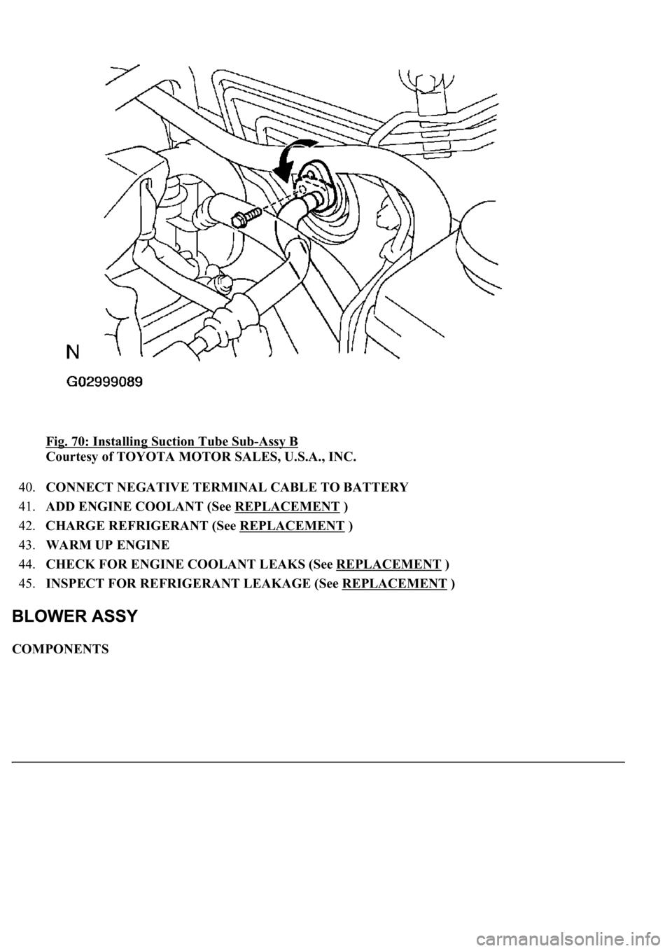
Fig. 70: Installing Suction Tube Sub-Assy B
Courtesy of TOYOTA MOTOR SALES, U.S.A., INC.
40.CONNECT NEGATIVE TERMINAL CABLE TO BATTERY
41.ADD ENGINE COOLANT (See REPLACEMENT
)
42.CHARGE REFRIGERANT (See REPLACEMENT
)
43.WARM UP ENGINE
44.CHECK FOR ENGINE COOLANT LEAKS (See REPLACEMENT
)
45.INSPECT FOR REFRIGERANT LEAKAGE (See REPLACEMENT
)
COMPONENTS
Page 4262 of 4500
a. Using a gas leak detector, check for leakage of refrigerant.
<002c004900030057004b0048005500480003004c0056000300440051005c0003004f00480044004e0044004a0048000f0003005500480053004f00440046004800030057004b00480003004600520050005300550048005600560052005500030044005600
56004800500045004f005c00110003[
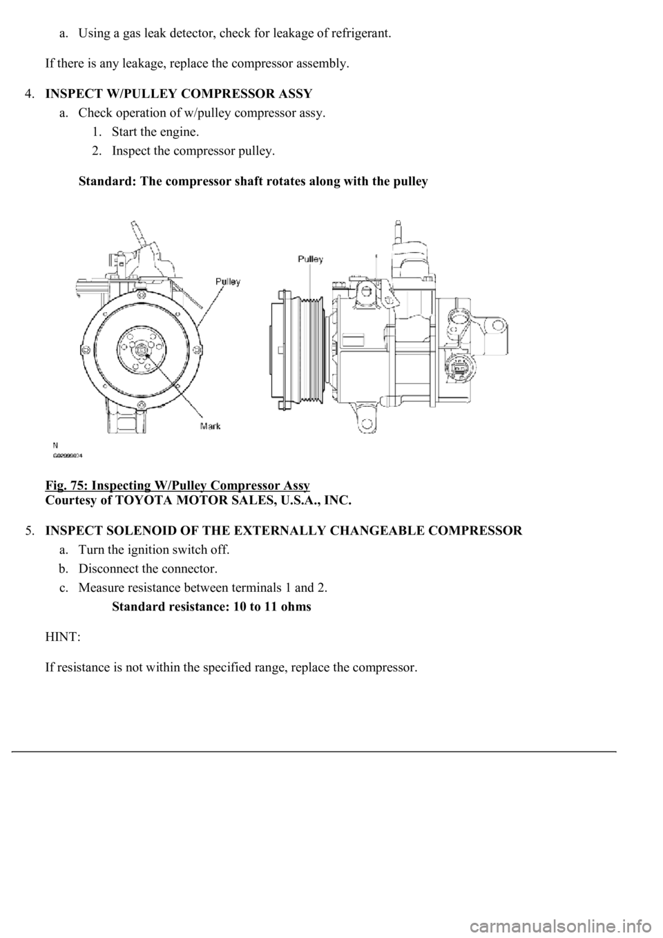
4.INSPECT W/PULLEY COMPRESSOR ASSY
a. Check operation of w/pulley compressor assy.
1. Start the engine.
2. Inspect the compressor pulley.
Standard: The compressor shaft rotates along with the pulley
Fig. 75: Inspecting W/Pulley Compressor Assy
Courtesy of TOYOTA MOTOR SALES, U.S.A., INC.
5.INSPECT SOLENOID OF THE EXTERNALLY CHANGEABLE COMPRESSOR
a. Turn the ignition switch off.
b. Disconnect the connector.
c. Measure resistance between terminals 1 and 2.
Standard resistance: 10 to 11 ohms
HINT:
If resistance is not within the specified ran
ge, replace the compressor.
Page 4291 of 4500
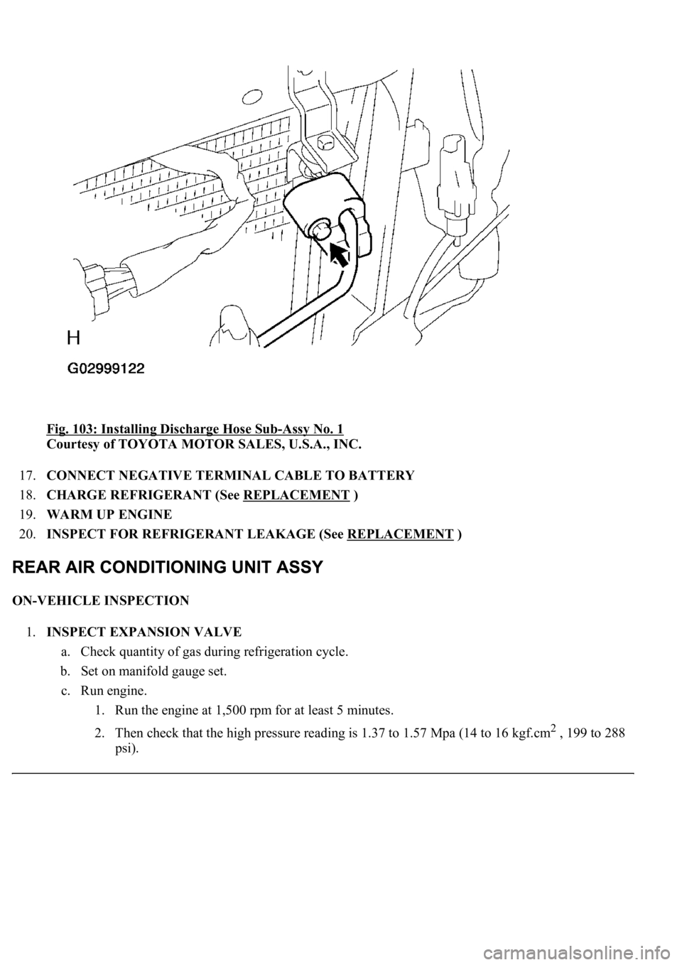
Fig. 103: Installing Discharge Hose Sub-Assy No. 1
Courtesy of TOYOTA MOTOR SALES, U.S.A., INC.
17.CONNECT NEGATIVE TERMINAL CABLE TO BATTERY
18.CHARGE REFRIGERANT (See REPLACEMENT
)
19.WARM UP ENGINE
20.INSPECT FOR REFRIGERANT LEAKAGE (See REPLACEMENT
)
ON-VEHICLE INSPECTION
1.INSPECT EXPANSION VALVE
a. Check quantity of gas during refrigeration cycle.
b. Set on manifold gauge set.
c. Run engine.
1. Run the engine at 1,500 rpm for at least 5 minutes.
2. Then check that the high pressure reading is 1.37 to 1.57 Mpa (14 to 16 kgf.cm
2 , 199 to 288
psi).
Page 4330 of 4500
6. Visually check if spark occurs while the engine is being cranked.
If a spark does not occur, perform the test as follows:
Fig. 4: Spark Test Flow Diagram
Courtesy of TOYOTA MOTOR SALES, U.S.A., INC.
7. Using a 16 mm (0.63 in.) plug wrench, install the spark plugs.
Torque: 18 N.m (180 kgf.cm, 13 ft.lbf)
8. Install the ignition coils (see REPLACEMENT
).
Page 4332 of 4500
If the resistance is less than the specified value, proceed to step (d).
HINT:
If the megaohmmeter is not available, perform the following simple inspection instead.
b. Alternative inspection method:
1. Quickly accelerate the engine to 4,000 rpm 5 times.
2. Remove the spark plug.
3. Visually check the spark plug.
If the electrode is dry, the spark plug is functioning. Reinstall the spark plug. Proceed to step
3.
If the electrode is damp, proceed to steps (c), (d) and (e).
Page 4342 of 4500
14.REFILL ENGINE COOLANT (See REPLACEMENT )
15.WARM UP ENGINE
16.CHECK FOR ENGINE COOLANT LEAKS
COMPONENTS
Page 4402 of 4500

Fig. 3: Inspecting Intake Air Control Function
Courtesy of TOYOTA MOTOR SALES, U.S.A., INC.
a. Remove the V-bank cover.
b. Connect the hand-held tester (with CAN VIM) to the DLC3.
c. Perform the ACTIVE TEST, and then check that the actuator rod operates.
d. Start the engine.
e. Check that the VSV for IAC valve in ON (seal) under these conditions.
Depressing the accelerator pedal to a throttle valve opening angle of 60 degrees.
Racing the engine above 4,700 rpm.
f. Check that the VSV for IAC valve is OFF (vent) under these conditions.
The engine is idling.
Releasing the accelerator pedal while under the 2 conditions in step (e).
If the result is not as specified, inspect the IAC valve, vacuum tank and VSV for normal operation.
Replace malfunctioning parts as necessary.
INSPECTION
1.INSPECT INTAKE AIR CONTROL VALVE ACTUATOR
a. Connect the MITYVAC (han
d-held vacuum pump) to the actuator.