Ecm LEXUS LS430 2003 Factory User Guide
[x] Cancel search | Manufacturer: LEXUS, Model Year: 2003, Model line: LS430, Model: LEXUS LS430 2003Pages: 4500, PDF Size: 87.45 MB
Page 261 of 4500

ECM (TAM - E2) TEST RESULT
B: PROCEED TO NEXT CIRCUIT INSPECTION SHOWN IN PROBLEM SYMPTOMS TABLE
C: REPLACE ECM (SEE REPLACEMENT )
A: Go to next step
3.INSPECT A/C AMBIENT TEMPERATURE SENSOR
a. Remove the A/C ambient temperature sensor.
b. Measure the resistance according to the value (s) in the table below.
Fig. 44: Identifying Terminals Of A/C Ambient Temperature Sensor Connector
Courtesy of TOYOTA MOTOR SALES, U.S.A., INC.
NGA
OK (Checking from the PROBLEM SYMPTOM TABLE)B
OK (Checking from the DTC)C
Page 263 of 4500

Courtesy of TOYOTA MOTOR SALES, U.S.A., INC.
NG: REPLACE A/C AMBIENT TEMPERATURE SENSOR
OK: Go to next step
4.CHECK HARNESS AND CONNECTOR (ECM-A/C AMBIENT TEMPERATURE SENSOR)
(SEE ELECTRONIC CIRCUIT INSPECTION PROCEDURE
)
a. Measure the resistance according to the value (s) in the table below.
Standard:
ECM-A/C AMBIENT TEMPERATURE SENSOR RESISTANCE
NG: REPAIR OR REPLACE HARNESS OR CONNECTOR
Tester connectionConditionSpecified condition
E3-18 (TAM) - A1-1AlwaysBelow 1 ohms
E5-28 (E2) - A1-2AlwaysBelow 1 ohms
E3-18 (TAM) - Body groundAlways10 kohms or higher
E5-28 (E2) - Body groundAlways10 kohms or higher
Page 264 of 4500

Fig. 46: Checking Harness And Connector (ECM-A/C Ambient Temperature Sensor)
Courtesy of TOYOTA MOTOR SALES, U.S.A., INC.
Page 265 of 4500

OK: REPLACE ECM (SEE REPLACEMENT)
CIRCUIT DESCRIPTION
This sensor detects the evaporator temperature and sends the appropriate signals to the A/C amplifier. It is used
for frost prevention, temperature and time-lag air flow control.
Fig. 47: DTC Detection Item Trouble Area Chart
Courtesy of TOYOTA MOTOR SALES, U.S.A., INC.
WIRING DIAGRAM
Fig. 48: Evaporator Temperature Sensor Circuit
Courtesy of TOYOTA MOTOR SALES, U.S.A., INC.
INSPECTION PROCEDURE
Page 1198 of 4500

Fig. 8: Wiring Diagram - Can Communication System (W/O LEXUS Navigation System)
Courtesy of TOYOTA MOTOR SALES, U.S.A., INC.
HINT:
The position of the terminus circuit differs in vehicles with and without the LEXUS navigation system.
The skid control ECU with actuator detects and stores steering sensor and yaw rate sensor DTCs and
performs DTC communication by receiving information from the steering sensor and yaw rate sensor.
The ECM detects and stores distance control ECU DTCs, and performs DTC communication by
receiving information from the distance control ECU.
The ECM uses the CAN communication system to perform DTC communication instead of the
Page 1199 of 4500

conventional communication line (SIL).
1.BRIEF DESCRIPTION
a. The CAN (Controller Area Network) is a serial data communication system for real time
application. It is a multiplex communication system equipped for a vehicle and has a high
communication speed (500 kbps) and the function to detect malfunctions.
b. By pairing the CANH and CANL bus lines, the CAN performs communication based on
differential voltage.
c. Many ECUs (sensors) installed on the vehicle operate by sharing information and communicating
with each other.
d. The CAN has two resistors of 120 ohms which are necessary to communicate with the main bus
line.
2.DEFINITION OF TERMS
a. Main bus line
1. The main bus line is the wire harness between the two terminus circuits on the bus
(communication line). This is the main bus in the CAN communication system.
b. Sub bus line
1. The sub bus line is the wire harness which diverges from the main bus line to the ECU or
sensor.
c. Terminus circuit
1. The terminus circuit is a circuit which is placed to convert communication current of the
CAN communication into bus voltage. It consists of a resistor and condenser. Two terminus
circuits are necessary on a bus.
d. CAN J/C
1. The CAN J/C is a junction designed for CAN communication, which stores a terminus
circuit.
3.ECUs OR SENSORS WHICH COMMUNICATE THROUGH CAN COMMUNICATION
SYSTEM
a. Skid Control ECU with Actuator
b. Yaw Rate Sensor
c. Steering Sensor
d. Television Camera ECU
e. Seat Belt Control ECU
f. Distance Control ECU
g. Suspension Control ECU
h. ECM
i. Gateway ECU
4.DIAGNOSTIC CODE FOR CAN COMMUNICATION SYSTEM
a. DTCs for the CAN communication system are as follows:
Page 1204 of 4500
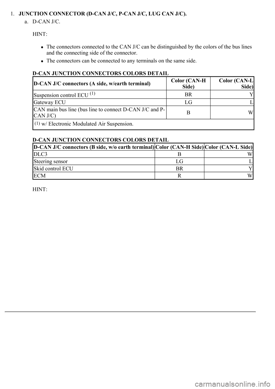
1.JUNCTION CONNECTOR (D-CAN J/C, P-CAN J/C, LUG CAN J/C).
a. D-CAN J/C.
HINT:
The connectors connected to the CAN J/C can be distinguished by the colors of the bus lines
and the connecting side of the connector.
<0037004b00480003004600520051005100480046005700520055005600030046004400510003004500480003004600520051005100480046005700480047000300570052000300440051005c00030057004800550050004c00510044004f00560003005200
5100030057004b00480003005600440050004800030056004c[de.
D-CAN JUNCTION CONNECTORS COLORS DETAIL
D-CAN JUNCTION CONNECTORS COLORS DETAIL
HINT:
D-CAN J/C connectors (A side, w/earth terminal)Color (CAN-H
Side)Color (CAN-L
Side)
Suspension control ECU (1)BRY
Gateway ECULGL
CAN main bus line (bus line to connect D-CAN J/C and P-
CAN J/C)BW
(1)w/ Electronic Modulated Air Suspension.
D-CAN J/C connectors (B side, w/o earth terminal)Color (CAN-H Side)Color (CAN-L Side)
DLC3BW
Steering sensorLGL
Skid control ECUBRY
ECMRW
Page 1212 of 4500

Fig. 16: Identifying DCL3 Connector Terminals
Courtesy of TOYOTA MOTOR SALES, U.S.A., INC.
2.DLC3
a. Measure the resistance according to the value (s) in the table below.
Standard:
ECM CONNECTOR TERMINALS RESISTANCE
TerminalsWiring ColorConditionSpecified Condition
D1-6 (CANH) - D1-14 (CANL)B - WIgnition Switch OFF54 to 69 ohms
D1-6 (CANH) - D1-4 (CG)B - W-BIgnition Switch OFF1 kohms or more
D1-14 (CANL) - D1-4 (CG)W - W-BIgnition Switch OFF1 kohms or more
D1-6 (CANH) - D1-16 (BAT)B - BIgnition Switch OFF1 Mohms or more
D1-14 (CANL) - D1-16 (BAT)W - BIgnition Switch OFF1 Mohms or more
Page 1219 of 4500

TELEVISION CAMERA ECU CONNECTOR TERMINALS RESISTANCE
Fig. 22: Identifying ECM Connector Terminals
Courtesy of TOYOTA MOTOR SALES, U.S.A., INC.
8.ECM
a. Measure the resistance according to the value (s) in the table below.
Standard:
ECM CONNECTOR TERMINALS RESISTANCE
TerminalsWiring ColorConditionSpecified Condition
T24-8 (CANH) - T24-7 (CANL)LG - LIgnition Switch OFF54 to 69 ohms
T24-8 (CANH) - T25-8 (GND1)LG - W-BIgnition Switch OFF1 kohms or more
T24-7 (CANL) - T25-8 (GND1)L - W-BIgnition Switch OFF1 kohms or more
T24-8 (CANH) - T25-1 (+B)LG - RIgnition Switch OFF1 Mohms or more
T24-7 (CANL) - T25-1 (+B)L - RIgnition Switch OFF1 Mohms or more
TerminalsWiring ColorConditionSpecified Condition
E3-25 (CANH) - E3-24 (CANL)R- WIgnition Switch OFF54 to 69 ohms
E3-25 (CANH) - E3-2 (EC)R - W-BIgnition Switch OFF1 kohms or more
E3-24 (CANL) - E3-2 (EC)W - W-BIgnition Switch OFF1 kohms or more
Page 1223 of 4500
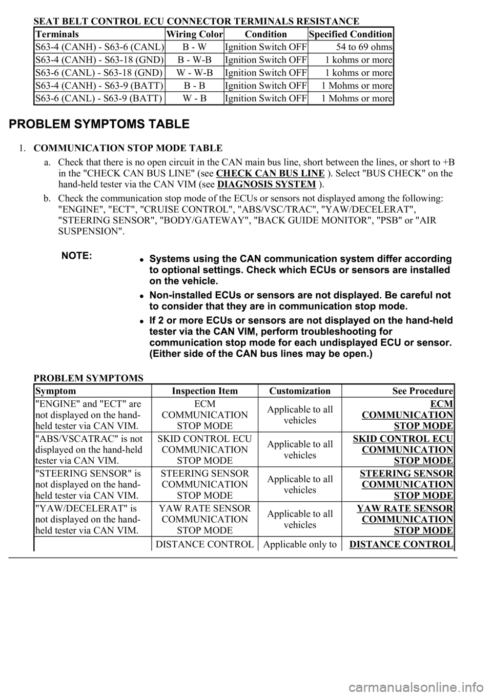
SEAT BELT CONTROL ECU CONNECTOR TERMINALS RESISTANCE
1.COMMUNICATION STOP MODE TABLE
a. Check that there is no open circuit in the CAN main bus line, short between the lines, or short to +B
in the "CHECK CAN BUS LINE" (see CHECK CAN BUS LINE
). Select "BUS CHECK" on the
hand-held tester via the CAN VIM (see DIAGNOSIS SYSTEM
).
b. Check the communication stop mode of the ECUs or sensors not displayed among the following:
"ENGINE", "ECT", "CRUISE CONTROL", "ABS/VSC/TRAC", "YAW/DECELERAT",
"STEERING SENSOR", "BODY/GATEWAY", "BACK GUIDE MONITOR", "PSB" or "AIR
SUSPENSION".
PROBLEM SYMPTOMS
TerminalsWiring ColorConditionSpecified Condition
S63-4 (CANH) - S63-6 (CANL)B - WIgnition Switch OFF54 to 69 ohms
S63-4 (CANH) - S63-18 (GND)B - W-BIgnition Switch OFF1 kohms or more
S63-6 (CANL) - S63-18 (GND)W - W-BIgnition Switch OFF1 kohms or more
S63-4 (CANH) - S63-9 (BATT)B - BIgnition Switch OFF1 Mohms or more
S63-6 (CANL) - S63-9 (BATT)W - BIgnition Switch OFF1 Mohms or more
SymptomInspection ItemCustomizationSee Procedure
"ENGINE" and "ECT" are
not displayed on the hand-
held tester via CAN VIM.ECM
COMMUNICATION
STOP MODEApplicable to all
vehiclesECM
COMMUNICATION
STOP MODE
"ABS/VSCATRAC" is not
displayed on the hand-held
tester via CAN VIM.SKID CONTROL ECU
COMMUNICATION
STOP MODEApplicable to all
vehiclesSKID CONTROL ECU
COMMUNICATION
STOP MODE
"STEERING SENSOR" is
not displayed on the hand-
held tester via CAN VIM.STEERING SENSOR
COMMUNICATION
STOP MODEApplicable to all
vehiclesSTEERING SENSOR
COMMUNICATION
STOP MODE
"YAW/DECELERAT" is
not displayed on the hand-
held tester via CAN VIM.YAW RATE SENSOR
COMMUNICATION
STOP MODEApplicable to all
vehiclesYAW RATE SENSOR
COMMUNICATION
STOP MODE
DISTANCE CONTROL Applicable only to DISTANCE CONTROL