LEXUS LS430 2003 Factory User Guide
LS430 2003
LEXUS
LEXUS
https://www.carmanualsonline.info/img/36/57050/w960_57050-0.png
LEXUS LS430 2003 Factory User Guide
Page 111 of 4500
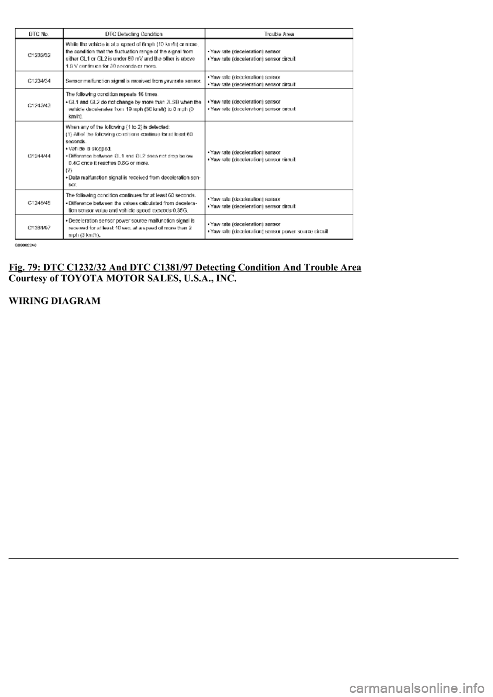
Fig. 79: DTC C1232/32 And DTC C1381/97 Detecting Condition And Trouble Area
Courtesy of TOYOTA MOTOR SALES, U.S.A., INC.
WIRING DIAGRAM
Page 112 of 4500
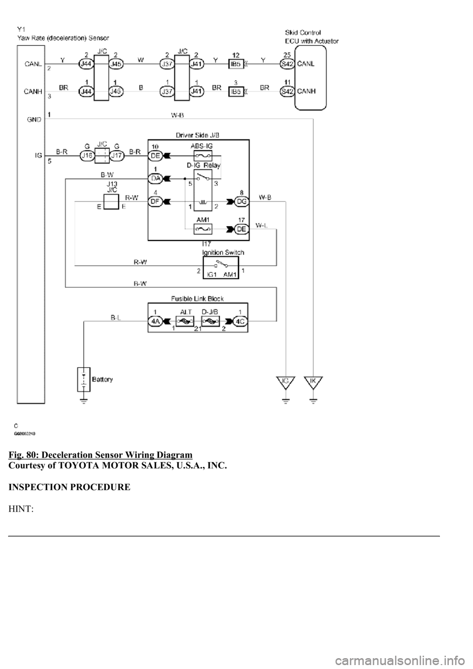
Fig. 80: Deceleration Sensor Wiring Diagram
Courtesy of TOYOTA MOTOR SALES, U.S.A., INC.
INSPECTION PROCEDURE
HINT:
Page 122 of 4500
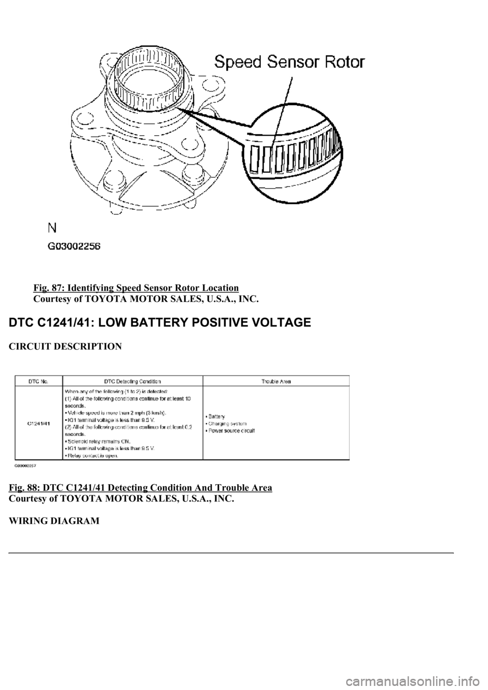
Fig. 87: Identifying Speed Sensor Rotor Location
Courtesy of TOYOTA MOTOR SALES, U.S.A., INC.
CIRCUIT DESCRIPTION
Fig. 88: DTC C1241/41 Detecting Condition And Trouble Area
Courtesy of TOYOTA MOTOR SALES, U.S.A., INC.
WIRING DIAGRAM
Page 123 of 4500
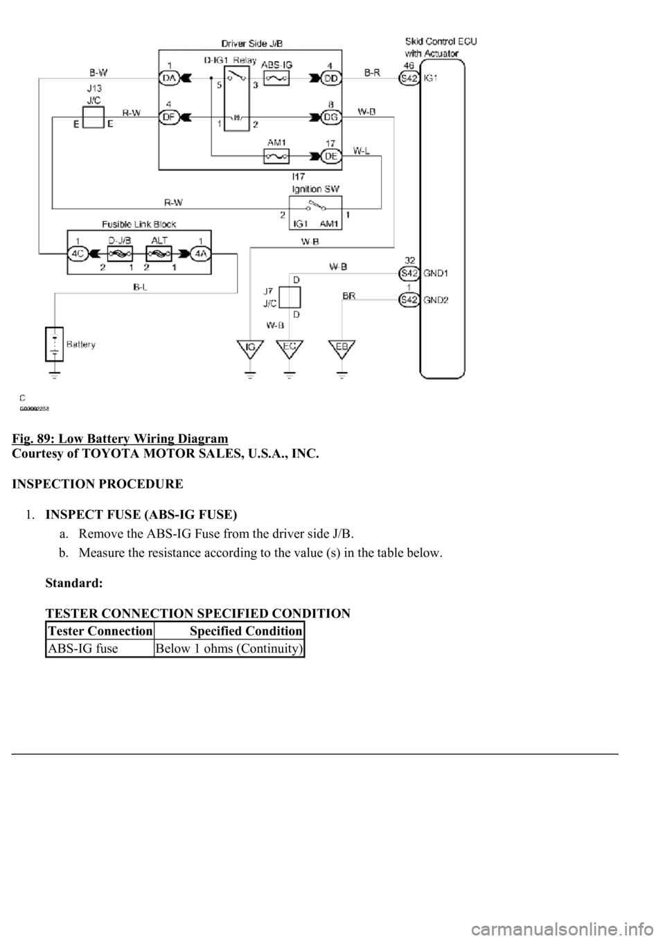
Fig. 89: Low Battery Wiring Diagram
Courtesy of TOYOTA MOTOR SALES, U.S.A., INC.
INSPECTION PROCEDURE
1.INSPECT FUSE (ABS-IG FUSE)
a. Remove the ABS-IG Fuse from the driver side J/B.
b. Measure the resistance according to the value (s) in the table below.
Standard:
TESTER CONNECTION SPECIFIED CONDITION
Tester ConnectionSpecified Condition
ABS-IG fuseBelow 1 ohms (Continuity)
Page 129 of 4500
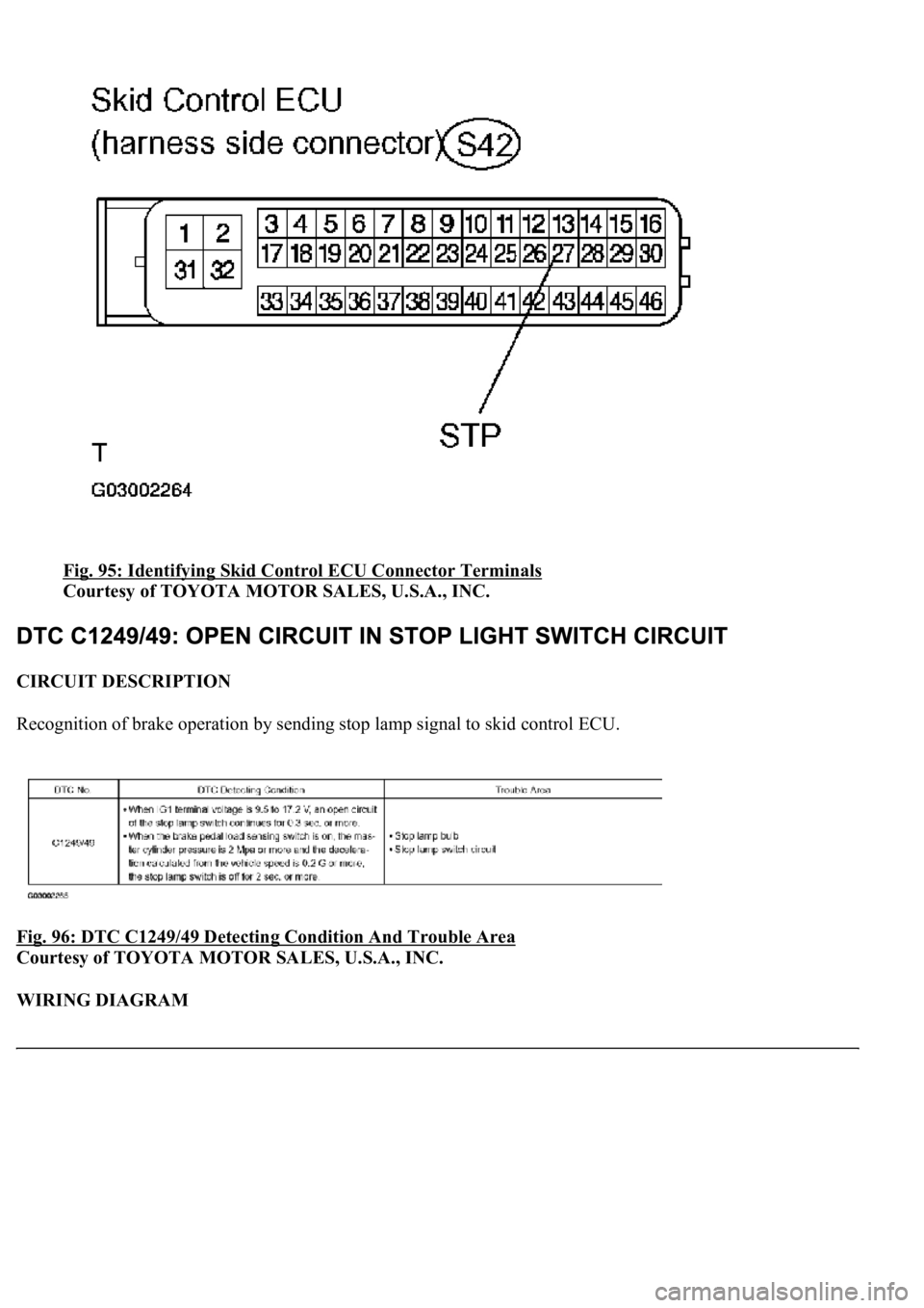
Fig. 95: Identifying Skid Control ECU Connector Terminals
Courtesy of TOYOTA MOTOR SALES, U.S.A., INC.
CIRCUIT DESCRIPTION
Recognition of brake operation by sending stop lamp signal to skid control ECU.
Fig. 96: DTC C1249/49 Detecting Condition And Trouble Area
Courtesy of TOYOTA MOTOR SALES, U.S.A., INC.
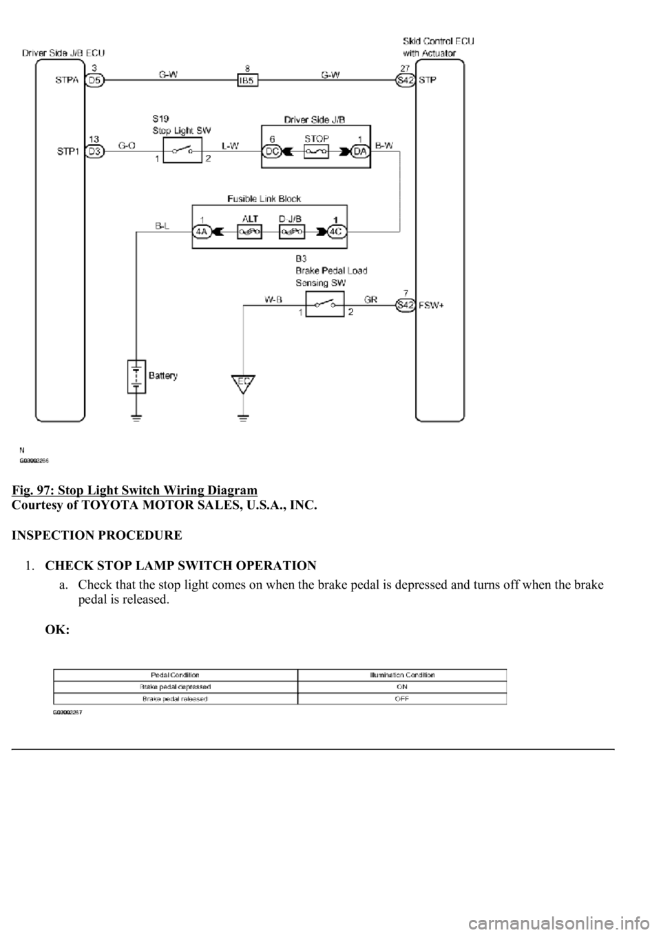
WIRING DIAGRAM
Page 130 of 4500
Fig. 97: Stop Light Switch Wiring Diagram
Courtesy of TOYOTA MOTOR SALES, U.S.A., INC.
INSPECTION PROCEDURE
1.CHECK STOP LAMP SWITCH OPERATION
a. Check that the stop light comes on when the brake pedal is depressed and turns off when the brake
pedal is released.
OK:
Page 140 of 4500
OK: Go to next step
9.RECONFIRM DTC
a. Clear the DTC (see DTC CHECK/CLEAR
).
b. Turn the ignition switch to the ON position.
c. Check that the same DTC is recorded (see DTC CHECK/CLEAR
).
OK:
The same DTC is recorded.
NG: PROCEED TO NEXT CIRCUIT INSPECTION SHOWN IN PROBLEM SYMPTOMS
TABLE
OK: REPLACE ABS & TRACTION ACTUATOR ASSY (SEE REPLACEMENT
)
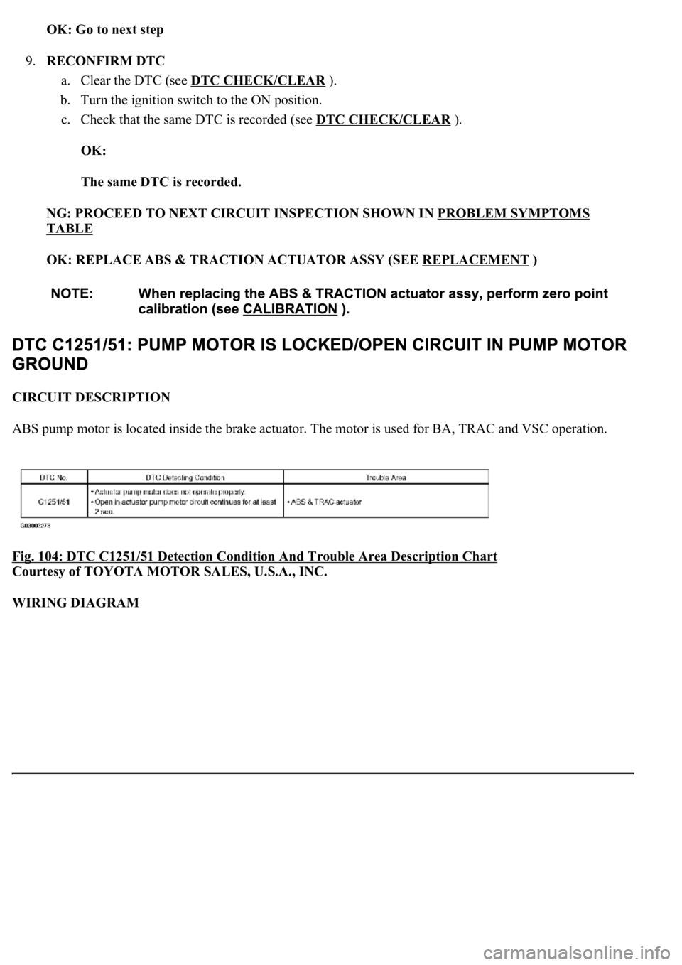
CIRCUIT DESCRIPTION
ABS pump motor is located inside the brake actuator. The motor is used for BA, TRAC and VSC operation.
Fig. 104: DTC C1251/51 Detection Condition And Trouble Area Description Chart
Courtesy of TOYOTA MOTOR SALES, U.S.A., INC.
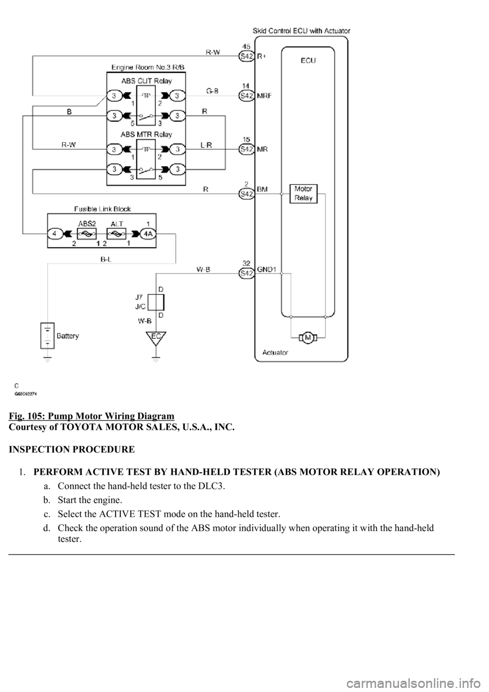
WIRING DIAGRAM
Page 141 of 4500
Fig. 105: Pump Motor Wiring Diagram
Courtesy of TOYOTA MOTOR SALES, U.S.A., INC.
INSPECTION PROCEDURE
1.PERFORM ACTIVE TEST BY HAND-HELD TESTER (ABS MOTOR RELAY OPERATION)
a. Connect the hand-held tester to the DLC3.
b. Start the engine.
c. Select the ACTIVE TEST mode on the hand-held tester.
d. Check the operation sound of the ABS motor individually when operating it with the hand-held
tester.
Page 144 of 4500
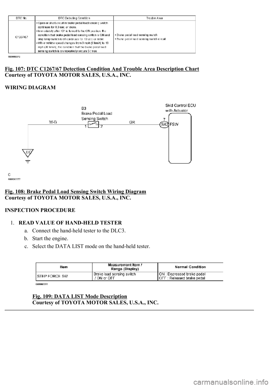
Fig. 107: DTC C1267/67 Detection Condition And Trouble Area Description Chart
Courtesy of TOYOTA MOTOR SALES, U.S.A., INC.
WIRING DIAGRAM
Fig. 108: Brake Pedal Load Sensing Switch Wiring Diagram
Courtesy of TOYOTA MOTOR SALES, U.S.A., INC.
INSPECTION PROCEDURE
1.READ VALUE OF HAND-HELD TESTER
a. Connect the hand-held tester to the DLC3.
b. Start the engine.
c. Select the DATA LIST mode on the hand-held tester.
Fig. 109: DATA LIST Mode Description
Courtesy of TOYOTA MOTOR SALES, U.S.A., INC.
Page 149 of 4500
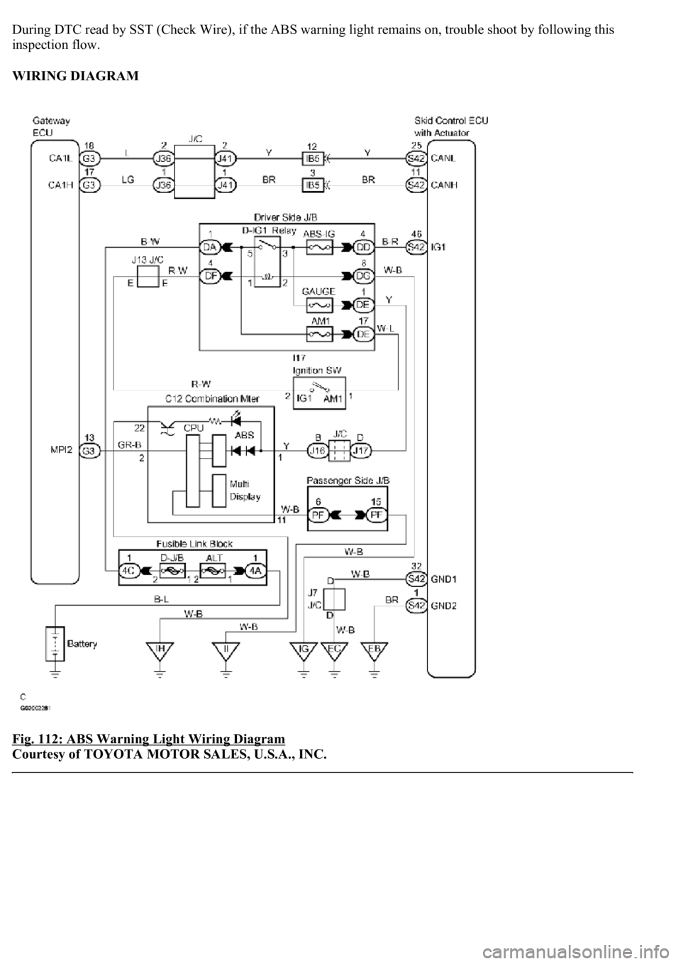
During DTC read by SST (Check Wire), if the ABS warning light remains on, trouble shoot by following this
inspection flow.
WIRING DIAGRAM
Fig. 112: ABS Warning Light Wiring Diagram
Courtesy of TOYOTA MOTOR SALES, U.S.A., INC.
