engine coolant LEXUS LS430 2003 Factory User Guide
[x] Cancel search | Manufacturer: LEXUS, Model Year: 2003, Model line: LS430, Model: LEXUS LS430 2003Pages: 4500, PDF Size: 87.45 MB
Page 1864 of 4500
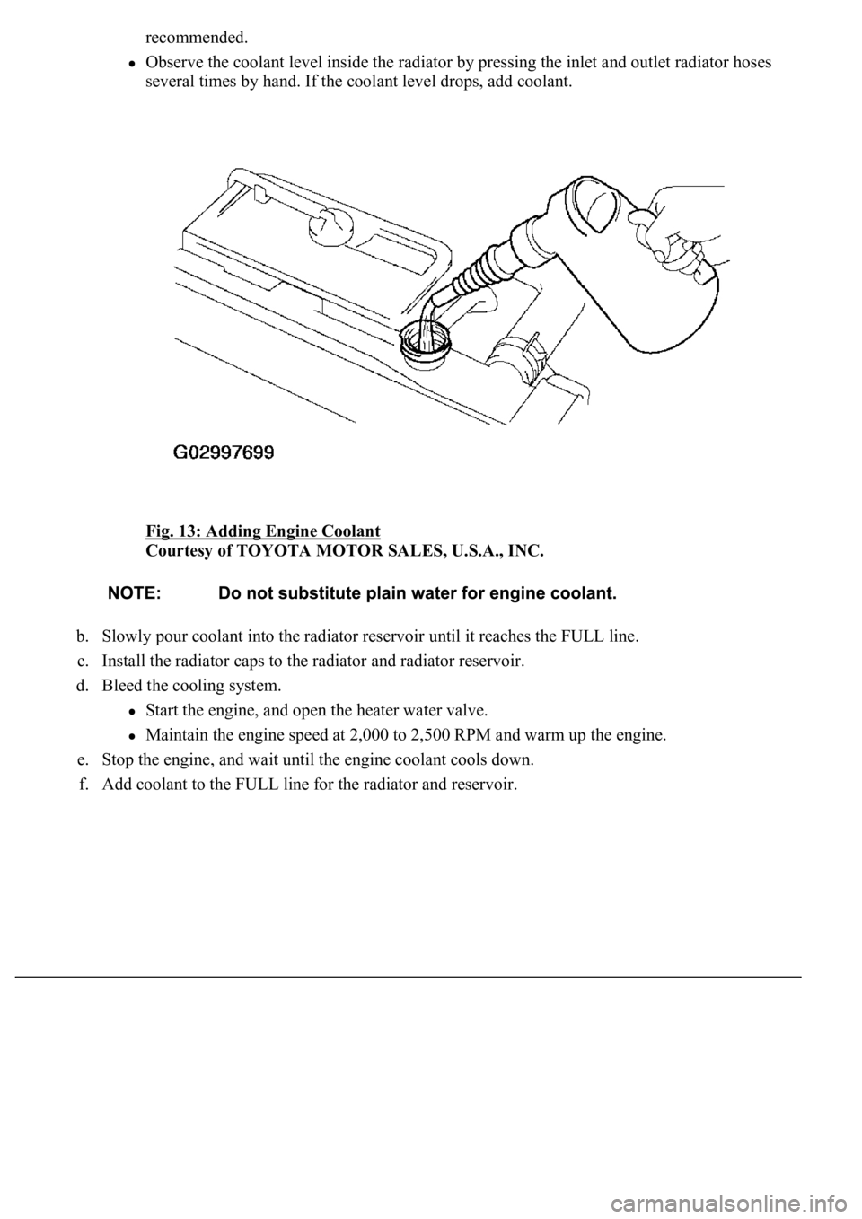
recommended.
<003200450056004800550059004800030057004b00480003004600520052004f0044005100570003004f004800590048004f0003004c00510056004c0047004800030057004b00480003005500440047004c004400570052005500030045005c0003005300
55004800560056004c0051004a00030057004b00480003004c[nlet and outlet radiator hoses
several times by hand. If the coolant level drops, add coolant.
Fig. 13: Adding Engine Coolant
Courtesy of TOYOTA MOTOR SALES, U.S.A., INC.
b. Slowly pour coolant into the radiator reservoir until it reaches the FULL line.
c. Install the radiator caps to the radiator and radiator reservoir.
d. Bleed the cooling system.
Start the engine, and open the heater water valve.
<00300044004c005100570044004c005100030057004b0048000300480051004a004c0051004800030056005300480048004700030044005700030015000f00130013001300030057005200030015000f001800130013000300350033003000030044005100
470003005a00440055005000030058005300030057004b0048[ engine.
e. Stop the engine, and wait until the engine coolant cools down.
f. Add coolant to the FULL line for the radiator and reservoir.
Page 1865 of 4500
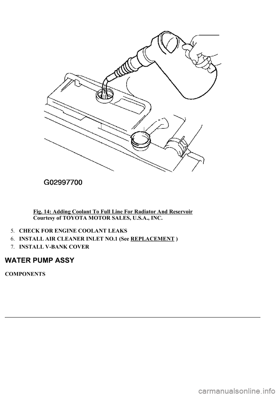
Fig. 14: Adding Coolant To Full Line For Radiator And Reservoir
Courtesy of TOYOTA MOTOR SALES, U.S.A., INC.
5.CHECK FOR ENGINE COOLANT LEAKS
6.INSTALL AIR CLEANER INLET NO.1 (See REPLACEMENT
)
7.INSTALL V-BANK COVER
COMPONENTS
Page 1869 of 4500
1.DISCONNECT BATTERY NEGATIVE TERMINAL
2.DRAIN ENGINE COOLANT (See REPLACEMENT
)
3.REMOVE ENGINE UNDER COVER NO.1
4.REMOVE RADIATOR ASSY
5.REMOVE TIMING BELT (See REPLACEMENT
)
6.REMOVE WATER INLET HOUSING
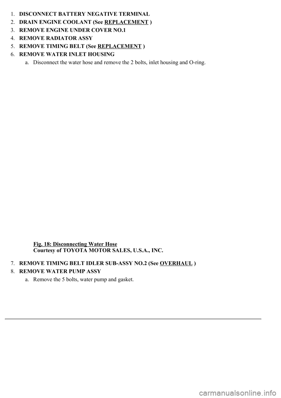
a. Disconnect the water hose and remove the 2 bolts, inlet housing and O-ring.
Fig. 18: Disconnecting Water Hose
Courtesy of TOYOTA MOTOR SALES, U.S.A., INC.
7.REMOVE TIMING BELT IDLER SUB-ASSY NO.2 (See OVERHAUL
)
8.REMOVE WATER PUMP ASSY
a. Remove the 5 bolts, water pump and
gasket.
Page 1872 of 4500
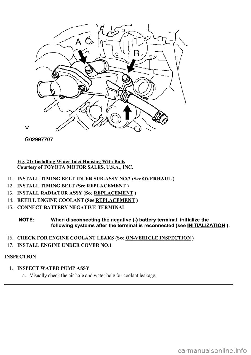
Fig. 21: Installing Water Inlet Housing With Bolts
Courtesy of TOYOTA MOTOR SALES, U.S.A., INC.
11.INSTALL TIMING BELT IDLER SUB-ASSY NO.2 (See OVERHAUL
)
12.INSTALL TIMING BELT (See REPLACEMENT
)
13.INSTALL RADIATOR ASSY (See REPLACEMENT
)
14.REFILL ENGINE COOLANT (See REPLACEMENT
)
15.CONNECT BATTERY NEGATIVE TERMINAL
16.CHECK FOR ENGINE COOLANT LEAKS (See ON
-VEHICLE INSPECTION )
17.INSTALL ENGINE UNDER COVER NO.1
INSPECTION
1.INSPECT WATER PUMP ASSY
a. Visuall
y<00030046004b00480046004e00030057004b004800030044004c00550003004b0052004f004800030044005100470003005a00440057004800550003004b0052004f004800030049005200550003004600520052004f0044005100570003004f0048004400
4e0044[ge.
Page 1873 of 4500
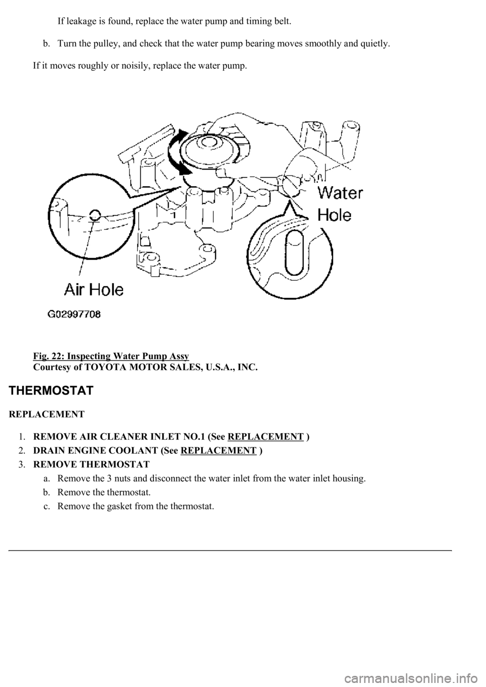
If leakage is found, replace the water pump and timing belt.
b. Turn the pulley, and check that the water pump bearing moves smoothly and quietly.
If it moves roughly or noisily, replace the water pump.
Fig. 22: Inspecting Water Pump Assy
Courtesy of TOYOTA MOTOR SALES, U.S.A., INC.
REPLACEMENT
1.REMOVE AIR CLEANER INLET NO.1 (See REPLACEMENT
)
2.DRAIN ENGINE COOLANT (See REPLACEMENT
)
3.REMOVE THERMOSTAT
a. Remove the 3 nuts and disconnect the water inlet from the water inlet housing.
b. Remove the thermostat.
c. Remove the
gasket from the thermostat.
Page 1876 of 4500
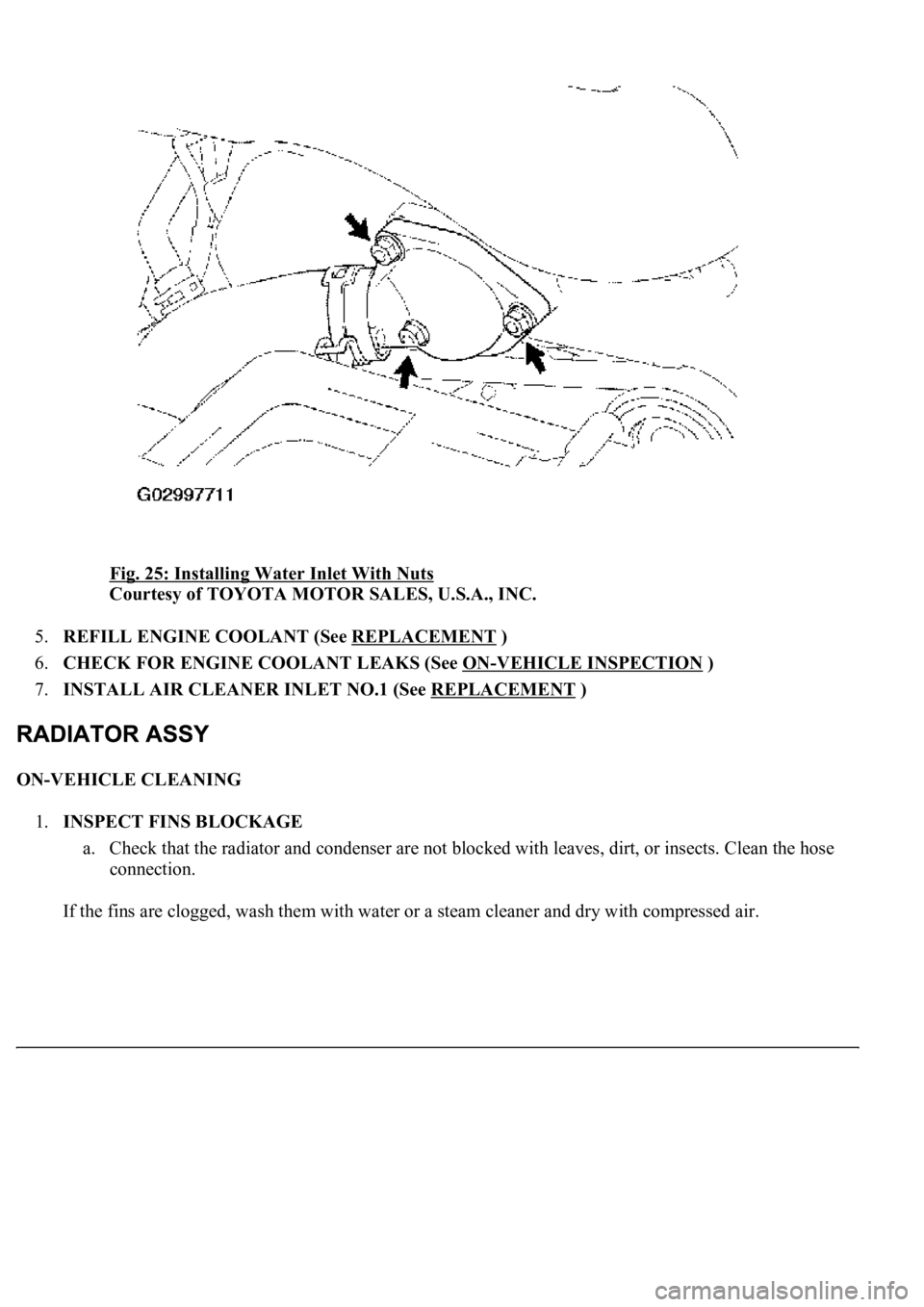
Fig. 25: Installing Water Inlet With Nuts
Courtesy of TOYOTA MOTOR SALES, U.S.A., INC.
5.REFILL ENGINE COOLANT (See REPLACEMENT
)
6.CHECK FOR ENGINE COOLANT LEAKS (See ON
-VEHICLE INSPECTION )
7.INSTALL AIR CLEANER INLET NO.1 (See REPLACEMENT
)
ON-VEHICLE CLEANING
1.INSPECT FINS BLOCKAGE
a. Check that the radiator and condenser are not blocked with leaves, dirt, or insects. Clean the hose
connection.
If the fins are clo
gged, wash them with water or a steam cleaner and dry with compressed air.
Page 1880 of 4500

3.REMOVE AIR CLEANER INLET NO.1
4.DRAIN ENGINE COOLANT (See REPLACEMENT
)
5.REMOVE V-BANK COVER
6.REMOVE INTAKE AIR CONNECTOR PIPE
7.DISCONNECT RADIATOR HOSE NO.1
8.DISCONNECT RADIATOR HOSE NO.2
9.DISCONNECT OIL COOLER INLET TUBE NO.1
10.DISCONNECT OIL COOLER OUTLET TUBE NO.1
11.REMOVE AIR CLEANER ASSY
12.REMOVE RADIATOR AND FAN ASSEMBLY
a. Disconnect the cooling fan ECU connector.
b. Remove the 2 nuts and 2 radiator upper supports.
c. Remove the radiator and fan assembly.
d. Remove the 2 radiator lower supports.
Fig. 29: Removing Nuts And Radiator Upper Supports
Courtesy of TOYOTA MOTOR SALES, U.S.A., INC.
Page 1881 of 4500
13.REMOVE FAN ASSY
a. Disconnect the radiator reservoir hose from the radiator.
b. Remove the 6 bolts and fan.
14.INSTALL FAN ASSY
a. Install the fan with the 6 bolts.
Torque: 5.0 Nm (51 kgfcm, 44 in.lbf)
b. Connect the radiator reservoir hose to the radiator.
15.INSTALL RADIATOR AND FAN ASSEMBLY
a. Install the 2 radiator lower supports to the radiator.
b. Attach the 2 radiator lower supports on the radiator to the body bracket.
c. Install the radiator and fan assembly with the 2 radiator upper supports and 2 nuts.
Torque: 13.5 N m (138 kgf cm, 10 ft lbf)
d. Connect the cooling fan ECU connector.
16.INSTALL AIR CLEANER ASSY
17.INSTALL AIR CLEANER INLET NO.1
18.REFILL ENGINE COOLANT (See REPLACEMENT
)
19.CHECK FOR ENGINE COOLANT LEAKS
20.INSTALL ENGINE UNDER COVER NO.1
21.CONNECT BATTERY NEGATIVE TERMINAL
OVERHAUL
1.REMOVE PACKING
2.REMOVE RADIATOR CAP SUB-ASSY
3.REMOVE DRAIN PLUG
a. Remove the drain plug.
b. Remove the O-ring.
4.ASSEMBLE SST
SST 09230-01010
a. Install the claw to the overhaul handle, inserting it in the hole in part A as shown in the illustration
b. While gripping the handle, adjust the stopper bolt so that dimension B is as shown in the
illustration.
Page 1898 of 4500
HINT:
The installation procedures are the removal procedures in reverse order. However, only installation procedures
requiring additional information are included.
1.DRAIN ENGINE COOLANT FROM RADIATOR (See REPLACEMENT
)
2.REMOVE AIR CLEANER INLET NO.1
3.REMOVE AIR CLEANER ASSY (See REPLACEMENT
)
4.DISCONNECT RADIATOR HOSE NO.1
5.REMOVE FAN ASSY
a. Disconnect the connector.
b. Remove the 6 bolts and fan.
6.REMOVE COOLING FAN ECU
a. Disconnect the 2 connectors.
b. Remove the 2 screws and ECU.
7.REMOVE FAN
a. Remove the 2 nuts and 2 fans.
8.REMOVE COOLING FAN MOTOR
a. Disconnect the 2 wires from the fan shroud.
b. Remove the 6 screws and 2 cooling fan motors.
Page 2015 of 4500
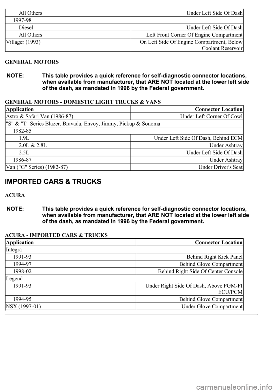
GENERAL MOTORS
GENERAL MOTORS - DOMESTIC LIGHT TRUCKS & VANS
ACURA
ACURA - IMPORTED CARS & TRUCKS
All OthersUnder Left Side Of Dash
1997-98
DieselUnder Left Side Of Dash
All OthersLeft Front Corner Of Engine Compartment
Villager (1993)On Left Side Of Engine Compartment, Below
Coolant Reservoir
ApplicationConnector Location
Astro & Safari Van (1986-87)Under Left Corner Of Cowl
"S" & "T" Series Blazer, Bravada, Envoy, Jimmy, Pickup & Sonoma
1982-85
1.9LUnder Left Side Of Dash, Behind ECM
2.0L & 2.8LUnder Ashtray
2.5LUnder Left Side Of Dash
1986-87Under Ashtray
Van ("G" Series) (1982-87)Under Driver's Seat
ApplicationConnector Location
Integra
1991-93Behind Right Kick Panel
1994-97Behind Glove Compartment
1998-02Behind Right Side Of Center Console
Legend
1991-93Under Right Side Of Dash, Above PGM-FI
ECU/PCM
1994-95Behind Glove Compartment
NSX (1997-01)Under Glove Compartment