immobilizer LEXUS LS430 2003 Factory User Guide
[x] Cancel search | Manufacturer: LEXUS, Model Year: 2003, Model line: LS430, Model: LEXUS LS430 2003Pages: 4500, PDF Size: 87.45 MB
Page 3171 of 4500
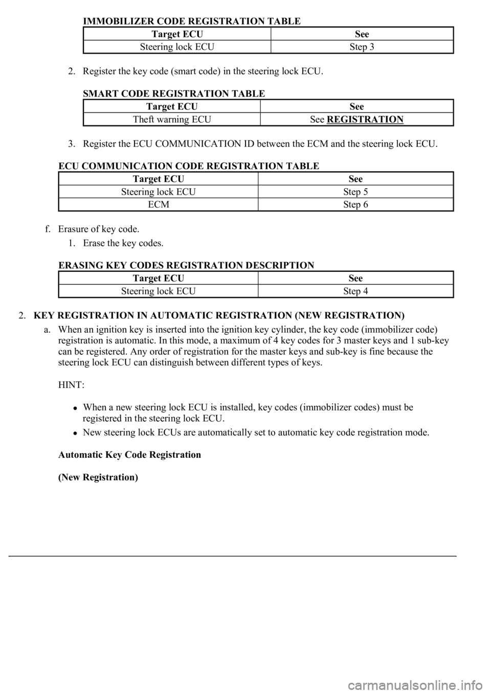
IMMOBILIZER CODE REGISTRATION TABLE
2. Register the key code (smart code) in the steering lock ECU.
SMART CODE REGISTRATION TABLE
3. Register the ECU COMMUNICATION ID between the ECM and the steering lock ECU.
ECU COMMUNICATION CODE REGISTRATION TABLE
f. Erasure of key code.
1. Erase the key codes.
ERASING KEY CODES REGISTRATION DESCRIPTION
2.KEY REGISTRATION IN AUTOMATIC REGISTRATION (NEW REGISTRATION)
a. When an ignition key is inserted into the ignition key cylinder, the key code (immobilizer code)
registration is automatic. In this mode, a maximum of 4 key codes for 3 master keys and 1 sub-key
can be registered. Any order of registration for the master keys and sub-key is fine because the
steering lock ECU can distinguish between different types of keys.
HINT:
When a new steering lock ECU is installed, key codes (immobilizer codes) must be
registered in the steering lock ECU.
New steering lock ECUs are automatically set to automatic key code registration mode.
Automatic Key Code Registration
(New Registration)
Target ECUSee
Steering lock ECUStep 3
Target ECUSee
Theft warning ECUSee REGISTRATION
Target ECUSee
Steering lock ECUStep 5
ECMStep 6
Target ECUSee
Steering lock ECUStep 4
Page 3172 of 4500
Fig. 4: Automatic Key Code Registration Flowchart (New Registration)
Courtesy of TOYOTA MOTOR SALES, U.S.A., INC.
HINT:
When no key is inserted into the ignition key cylinder in automatic key code registration
mode, the security indicator remains on.
When the immobilizer system is operating normally and the key is pulled out, the security
indicator blinks continuously.
If the key code registration has failed in automatic key code registration mode, code 2-1 will
be output from the security indicator. Trying to re-register an already registered key will
cause code 2-2 to be output when the key is inserted. If the number of registered key codes
Page 3174 of 4500
HINT:
The automatic key code registration mode can be forced to end when at least 1 key code (immobilizer
code) for the master key has been registered.
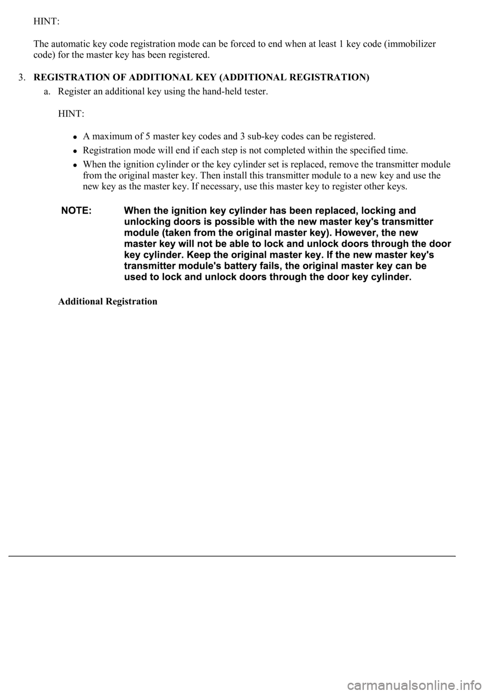
3.REGISTRATION OF ADDITIONAL KEY (ADDITIONAL REGISTRATION)
a. Register an additional key using the hand-held tester.
HINT:
A maximum of 5 master key codes and 3 sub-key codes can be registered.
Registration mode will end if each step is not completed within the specified time.
When the ignition cylinder or the key cylinder set is replaced, remove the transmitter module
from the original master key. Then install this transmitter module to a new key and use the
new key as the master key. If necessary, use this master key to register other keys.
Additional Registration
Page 3175 of 4500
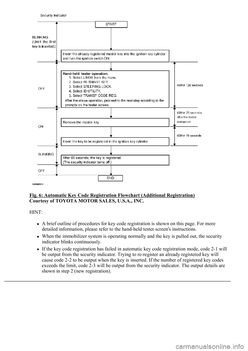
Fig. 6: Automatic Key Code Registration Flowchart (Additional Registration)
Courtesy of TOYOTA MOTOR SALES, U.S.A., INC.
HINT:
A brief outline of procedures for key code registration is shown on this page. For more
detailed information, please refer to the hand-held tester screen's instructions.
When the immobilizer system is operating normally and the key is pulled out, the security
indicator blinks continuously.
If the key code registration has failed in automatic key code registration mode, code 2-1 will
be output from the security indicator. Trying to re-register an already registered key will
cause code 2-2 to be output when the key is inserted. If the number of registered key codes
exceeds the limit, code 2-3 will be output from the security indicator. The output details are
shown in step 2 (new re
gistration).
Page 3176 of 4500
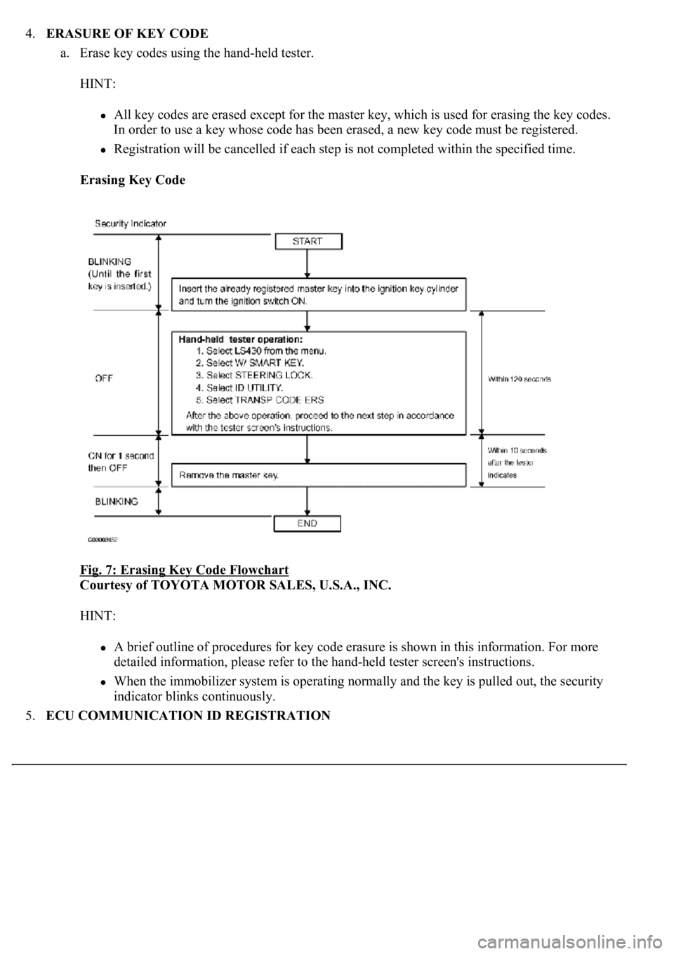
4.ERASURE OF KEY CODE
a. Erase key codes using the hand-held tester.
HINT:
All key codes are erased except for the master key, which is used for erasing the key codes.
In order to use a key whose code has been erased, a new key code must be registered.
Registration will be cancelled if each step is not completed within the specified time.
Erasing Key Code
Fig. 7: Erasing Key Code Flowchart
Courtesy of TOYOTA MOTOR SALES, U.S.A., INC.
HINT:
A brief outline of procedures for key code erasure is shown in this information. For more
detailed information, please refer to the hand-held tester screen's instructions.
When the immobilizer system is operating normally and the key is pulled out, the security
indicator blinks continuously.
5.ECU COMMUNICATION ID REGISTRATION
Page 3194 of 4500

Fig. 23: Identifying Waveform 2
Courtesy of TOYOTA MOTOR SALES, U.S.A., INC.
1.DESCRIPTION
a. The ECM controls the vehicle's immobilizer system functions. Immobilizer system data and the
Diagnostic Trouble Codes (DTCs) can be read through the vehicle's Data Link Connector 3
(DLC3). In some cases, a malfunction may be occurring in the immobilizer system even though the
security indicator lamp is not illuminated. When the system seems to be malfunctioning, use the
hand-held tester to check for malfunctions and perform repairs.
2.CHECK DLC3
HINT:
The vehicle uses the ISO 15765-4 communication protocol. The terminal arrangement of the DLC3
complies with SAE J1962 and matches the ISO 15765-4 format.
Page 3198 of 4500
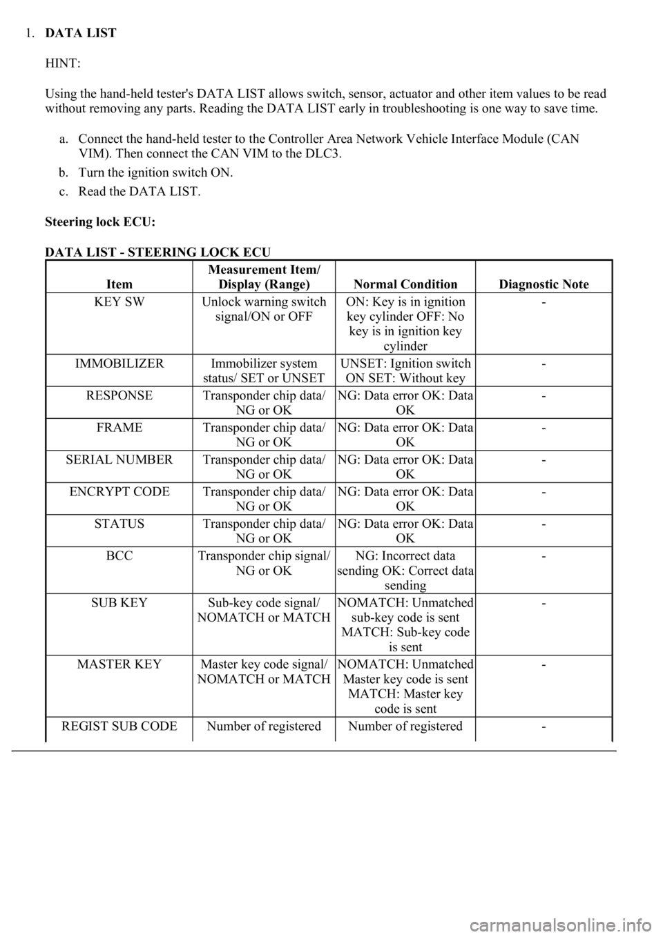
1.DATA LIST
HINT:
Using the hand-held tester's DATA LIST allows switch, sensor, actuator and other item values to be read
without removing any parts. Reading the DATA LIST early in troubleshooting is one way to save time.
a. Connect the hand-held tester to the Controller Area Network Vehicle Interface Module (CAN
VIM). Then connect the CAN VIM to the DLC3.
b. Turn the ignition switch ON.
c. Read the DATA LIST.
Steering lock ECU:
DATA LIST - STEERING LOCK ECU
Item
Measurement Item/
Display (Range)
Normal ConditionDiagnostic Note
KEY SWUnlock warning switch
signal/ON or OFFON: Key is in ignition
key cylinder OFF: No
key is in ignition key
cylinder-
IMMOBILIZERImmobilizer system
status/ SET or UNSETUNSET: Ignition switch
ON SET: Without key-
RESPONSETransponder chip data/
NG or OKNG: Data error OK: Data
OK-
FRAMETransponder chip data/
NG or OKNG: Data error OK: Data
OK-
SERIAL NUMBERTransponder chip data/
NG or OKNG: Data error OK: Data
OK-
ENCRYPT CODETransponder chip data/
NG or OKNG: Data error OK: Data
OK-
STATUSTransponder chip data/
NG or OKNG: Data error OK: Data
OK-
BCCTransponder chip signal/
NG or OKNG: Incorrect data
sending OK: Correct data
sending-
SUB KEYSub-key code signal/
NOMATCH or MATCHNOMATCH: Unmatched
sub-key code is sent
MATCH: Sub-key code
is sent-
MASTER KEYMaster key code signal/
NOMATCH or MATCHNOMATCH: Unmatched
Master key code is sent
MATCH: Master key
code is sent-
REGIST SUB CODENumber of registered Number of registered -
Page 3200 of 4500

1.STEERING LOCK ECU DTC CHART
Fig. 27: Steering Lock ECU DTC Chart
Courtesy of TOYOTA MOTOR SALES, U.S.A., INC.
2.ECM DTC CHART
Fig. 28: ECM DTC Chart
Courtesy of TOYOTA MOTOR SALES, U.S.A., INC.
DTC B2793TRANSPONDER CHIP MALFUNCTION
DTC B2794UNMATCHED ENCRYPTION CODE
DTC B2795UNMATCHED KEY CODE
DTC B2797COMMUNICATION MALFUNCTION NO.1
DTC B2799ENGINE IMMOBILIZER SYSTEM
MALFUNCTION
Page 3209 of 4500
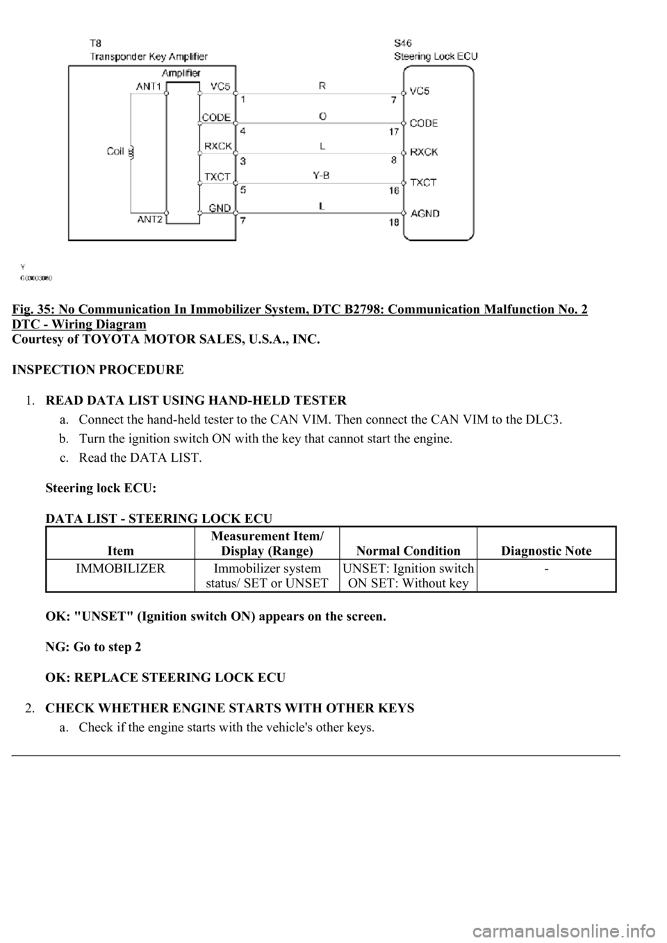
Fig. 35: No Communication In Immobilizer System, DTC B2798: Communication Malfunction No. 2
DTC - Wiring Diagram
Courtesy of TOYOTA MOTOR SALES, U.S.A., INC.
INSPECTION PROCEDURE
1.READ DATA LIST USING HAND-HELD TESTER
a. Connect the hand-held tester to the CAN VIM. Then connect the CAN VIM to the DLC3.
b. Turn the ignition switch ON with the key that cannot start the engine.
c. Read the DATA LIST.
Steering lock ECU:
DATA LIST - STEERING LOCK ECU
OK: "UNSET" (Ignition switch ON) appears on the screen.
NG: Go to step 2
OK: REPLACE STEERING LOCK ECU
2.CHECK WHETHER ENGINE STARTS WITH OTHER KEYS
a. Check if the en
gine starts with the vehicle's other keys.
Item
Measurement Item/
Display (Range)
Normal ConditionDiagnostic Note
IMMOBILIZERImmobilizer system
status/ SET or UNSETUNSET: Ignition switch
ON SET: Without key-
Page 3218 of 4500
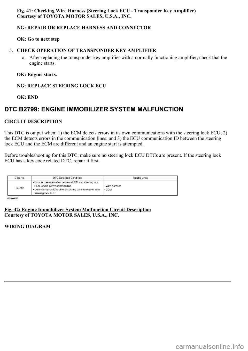
Fig. 41: Checking Wire Harness (Steering Lock ECU -Transponder Key Amplifier)
Courtesy of TOYOTA MOTOR SALES, U.S.A., INC.
NG: REPAIR OR REPLACE HARNESS AND CONNECTOR
OK: Go to next step
5.CHECK OPERATION OF TRANSPONDER KEY AMPLIFIER
a. After replacing the transponder key amplifier with a normally functioning amplifier, check that the
engine starts.
OK: Engine starts.
NG: REPLACE STEERING LOCK ECU
OK: END
CIRCUIT DESCRIPTION
This DTC is output when: 1) the ECM detects errors in its own communications with the steering lock ECU; 2)
the ECM detects errors in the communication lines; and 3) the ECU communication ID between the steering
lock ECU and the ECM are different and an engine start is attempted.
Before troubleshooting for this DTC, make sure no steering lock ECU DTCs are present. If the steering lock
ECU has a key code related DTC, repair it first.
Fig. 42: Engine Immobilizer System Malfunction Circuit Description
Courtesy of TOYOTA MOTOR SALES, U.S.A., INC.
WIRING DIAGRAM