wheel bolts LEXUS LS430 2003 Factory Repair Manual
[x] Cancel search | Manufacturer: LEXUS, Model Year: 2003, Model line: LS430, Model: LEXUS LS430 2003Pages: 4500, PDF Size: 87.45 MB
Page 851 of 4500
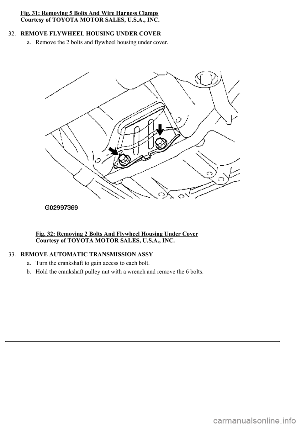
Fig. 31: Removing 5 Bolts And Wire Harness Clamps
Courtesy of TOYOTA MOTOR SALES, U.S.A., INC.
32.REMOVE FLYWHEEL HOUSING UNDER COVER
a. Remove the 2 bolts and flywheel housing under cover.
Fig. 32: Removing 2 Bolts And Flywheel Housing Under Cover
Courtesy of TOYOTA MOTOR SALES, U.S.A., INC.
33.REMOVE AUTOMATIC TRANSMISSION ASSY
a. Turn the crankshaft to gain access to each bolt.
b. Hold the crankshaft pulley nut with a wrench and remove the 6 bolts.
Page 866 of 4500
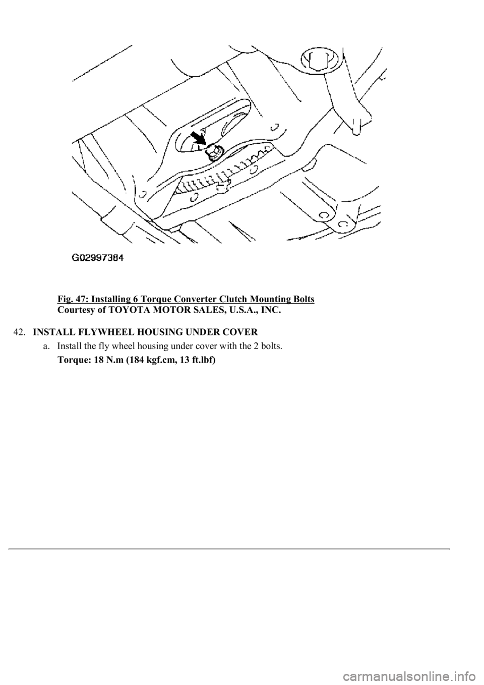
Fig. 47: Installing 6 Torque Converter Clutch Mounting Bolts
Courtesy of TOYOTA MOTOR SALES, U.S.A., INC.
42.INSTALL FLYWHEEL HOUSING UNDER COVER
a. Install the fly wheel housing under cover with the 2 bolts.
Torque: 18 N.m (184 kgf.cm, 13 ft.lbf)
Page 867 of 4500
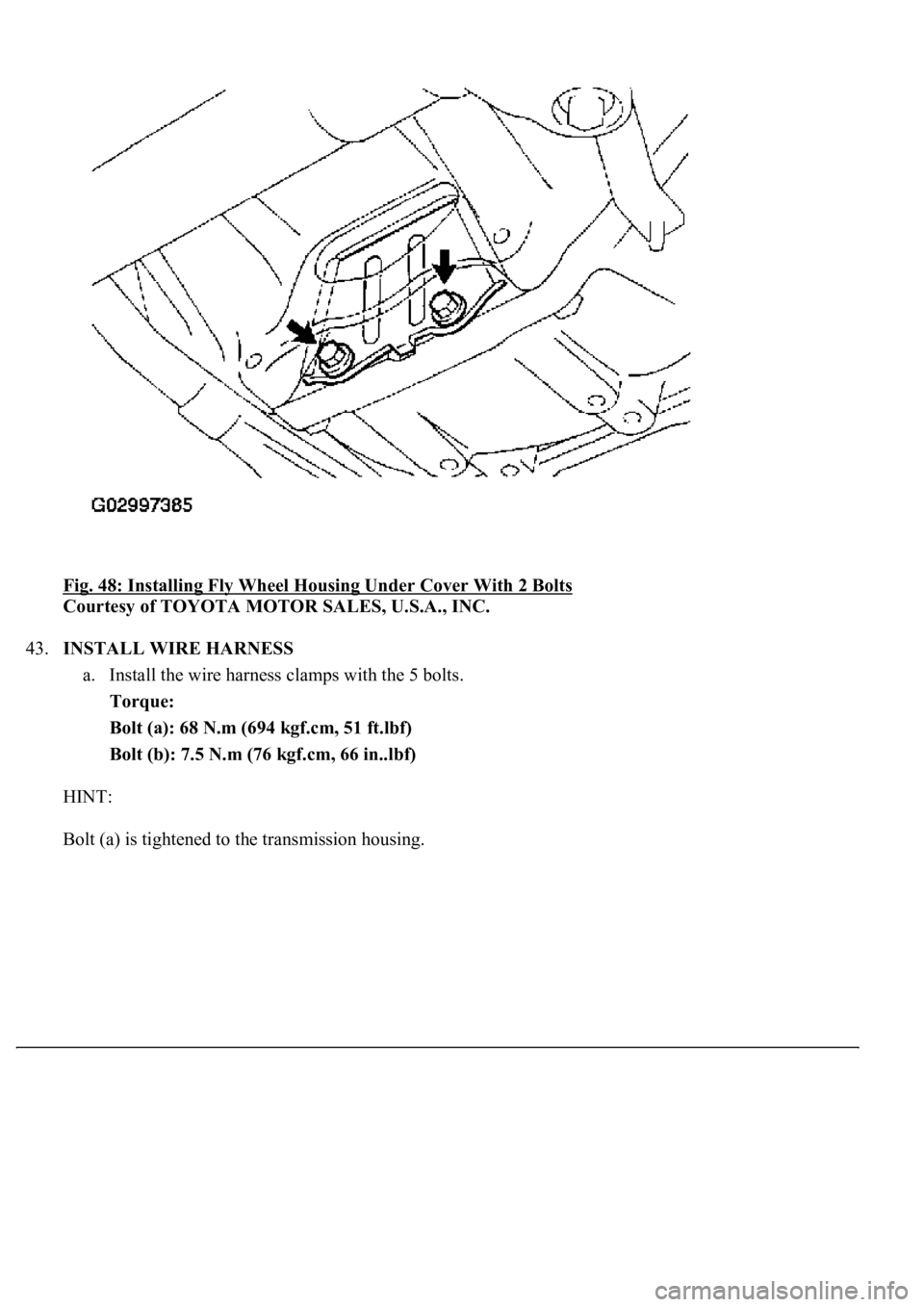
Fig. 48: Installing Fly Wheel Housing Under Cover With 2 Bolts
Courtesy of TOYOTA MOTOR SALES, U.S.A., INC.
43.INSTALL WIRE HARNESS
a. Install the wire harness clamps with the 5 bolts.
Torque:
Bolt (a): 68 N.m (694 kgf.cm, 51 ft.lbf)
Bolt (b): 7.5 N.m (76 kgf.cm, 66 in..lbf)
HINT:
Bolt (a) is ti
ghtened to the transmission housing.
Page 1145 of 4500
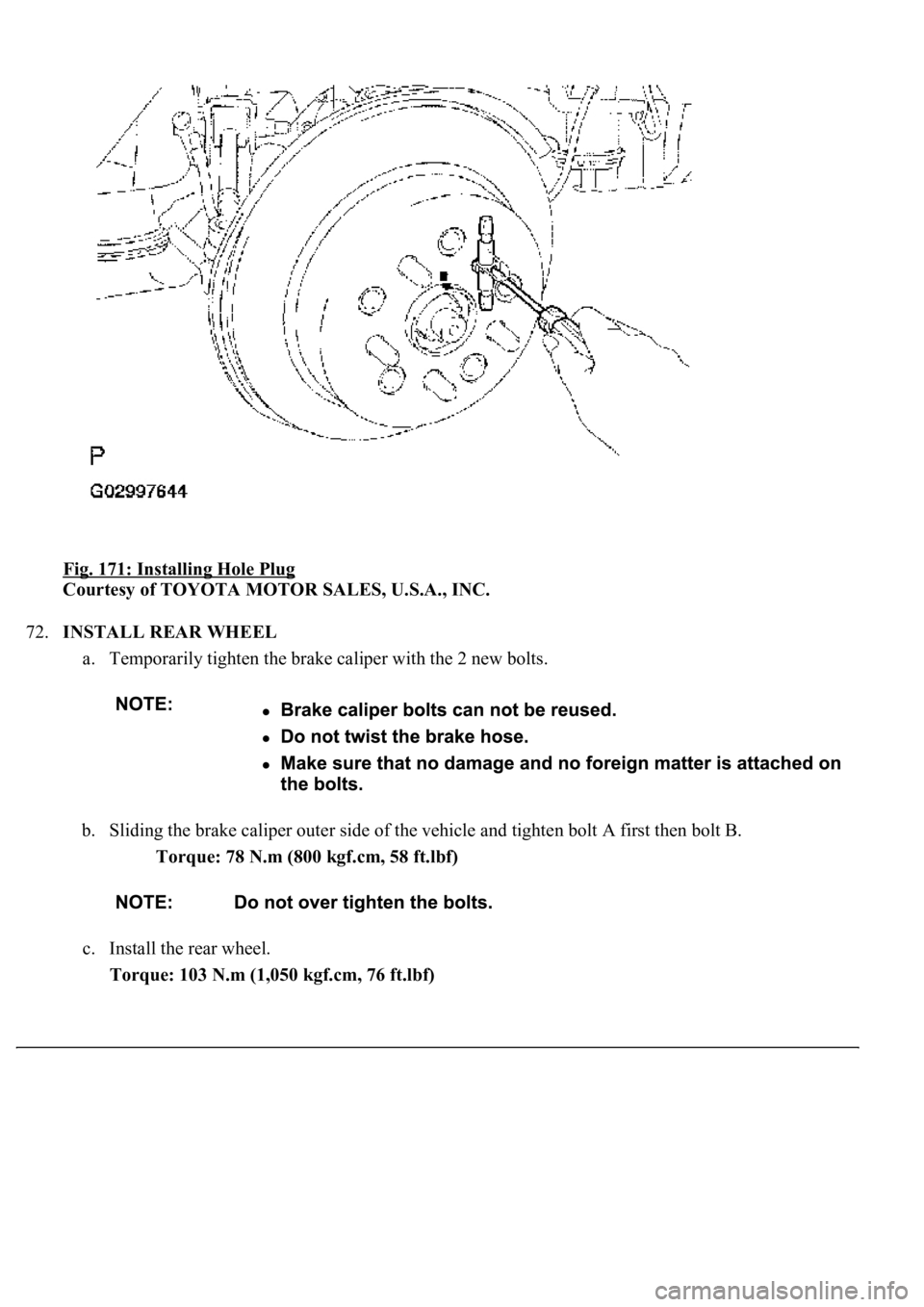
Fig. 171: Installing Hole Plug
Courtesy of TOYOTA MOTOR SALES, U.S.A., INC.
72.INSTALL REAR WHEEL
a. Temporarily tighten the brake caliper with the 2 new bolts.
b. Sliding the brake caliper outer side of the vehicle and tighten bolt A first then bolt B.
Torque: 78 N.m (800 kgf.cm, 58 ft.lbf)
c. Install the rear wheel.
Torque: 103 N.m (1,050 kgf.cm, 76 ft.lbf)
Page 1150 of 4500
Use the same procedures for the parking brake cable assy No.2 and No.3.
The procedures listed below are for the parking brake cable assy No.3.
1.REMOVE REAR WHEEL
2.SEPARATE REAR DISC BRAKE CALIPER ASSY LH
a. Remove the 2 bolts and separate the rear disc brake caliper assy LH.
HINT:
Do not disconnect the flexible hose from the rear disc brake caliper assy LH.
Do not twist or bend the rear brake caliper assy LH.
b. Hang the rear brake caliper assy LH with a piece of wire.
Fig. 175: Removing Bolts And Separate Rear Disc Brake Caliper Assy LH
Courtesy of TOYOTA MOTOR SALES, U.S.A., INC.
3.REMOVE REAR DISC
a. Place matchmarks on the disc and rear axle hub.
Page 1170 of 4500
Use the same procedures for the RH side and LH side.
The procedures listed below are for the LH side.
1.REMOVE REAR WHEEL
2.SEPARATE REAR DISC BRAKE CALIPER ASSY LH
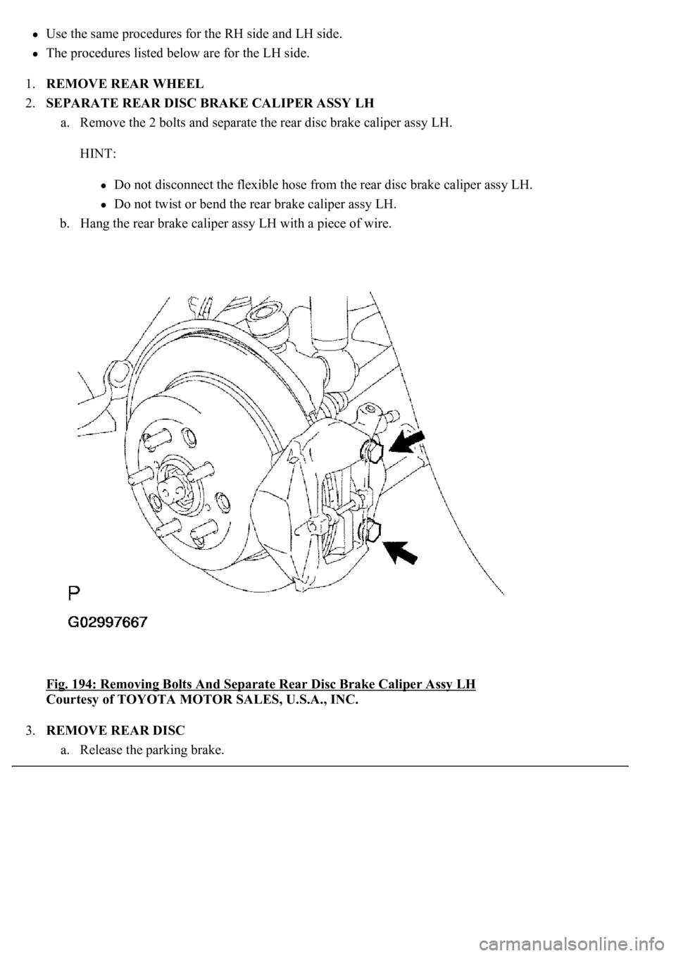
a. Remove the 2 bolts and separate the rear disc brake caliper assy LH.
HINT:
Do not disconnect the flexible hose from the rear disc brake caliper assy LH.
Do not twist or bend the rear brake caliper assy LH.
b. Hang the rear brake caliper assy LH with a piece of wire.
Fig. 194: Removing Bolts And Separate Rear Disc Brake Caliper Assy LH
Courtesy of TOYOTA MOTOR SALES, U.S.A., INC.
3.REMOVE REAR DISC
a. Release the parkin
g brake.
Page 2177 of 4500
a. Fill the rear differential carrier assy with differential gear oil equivalent.
Oil type: Differential synthetic gear oil GL-5 75W-90 or equivalent
Capacity: 1.35 +/- 0.05 liters (1.43 +/- 0.05 US qts, 1.19 +/- 0.04 Imp. qts)
67.INSPECT DIFFERENTIAL OIL (SEE ADJUSTMENT
)
68.INSTALL REAR DIFFERENTIAL FILLER PLUG
a. Using a hexagon wrench (10 mm), install the filler plug with a new gasket.
Torque: 49 N.m (500 kgf.cm, 36 ft.lbf)
69.INSTALL REAR DRIVE SHAFT ASSY LH (SEE REPLACEMENT
)
70.INSTALL REAR DRIVE SHAFT ASSY RH
HINT:
Installation procedure of the RH side is the same as that of the LH side.
71.INSTALL FRONT FLOOR HEAT INSULATOR NO.1
a. Install the front floor heat insulator No.1 with the 4 bolts.
Torque: 5.4 N.m (55 kgf.cm, 48 in..lbf)
72.INSTALL REAR WHEEL
a. Install the rear wheel with the 5 nuts.
Torque: 103 N.m (1,050 kgf.cm, 76 ft.lbf)
73. Install the ornament with the 10 bolts.
Torque: 20 N.m (204 kgf.cm, 15 ft.lbf)
74.INSTALL PROPELLER W/CENTER BEARING SHAFT ASSY (SEE OVERHAUL
)
75.FULLY TIGHTEN CENTER SUPPORT BEARING ASSY NO.1 (SEE OVERHAUL
)
SST 09922-10010
76.INSPECT AND ADJUST NO.2 AND NO.3 JOINT ANGLE (SEE OVERHAUL
)
77.INSTALL PROPELLER SHAFT HEAT INSULATOR (SEE OVERHAUL
)
78.INSTALL EXHAUST PIPE ASSY (SEE REPLACEMENT
)
79.INSTALL OXYGEN SENSOR (SEE REPLACEMENT
)
80.INSPECT AND ADJUST REAR WHEEL ALIGNMENT (SEE ADJUSTMENT
)
81.ADJUST VEHICLE HEIGHT (W/ AIR SUSPENSION) (SEE ON
-VEHICLE INSPECTION )
82.INSPECT HEADLIGHT AIM ONLY (SEE ADJUSTMENT
)
83.CHECK ABS SPEED SENSOR SIGNAL (SEE TEST MODE PROCEDURE
)
84.INSPECT AIR LEAK (W/ AIR SUSPENSION) (SEE REPLACEMENT
)
HINT:
Perform this operation onl
y when the rear differential mount cushion is replaced.
Page 2305 of 4500
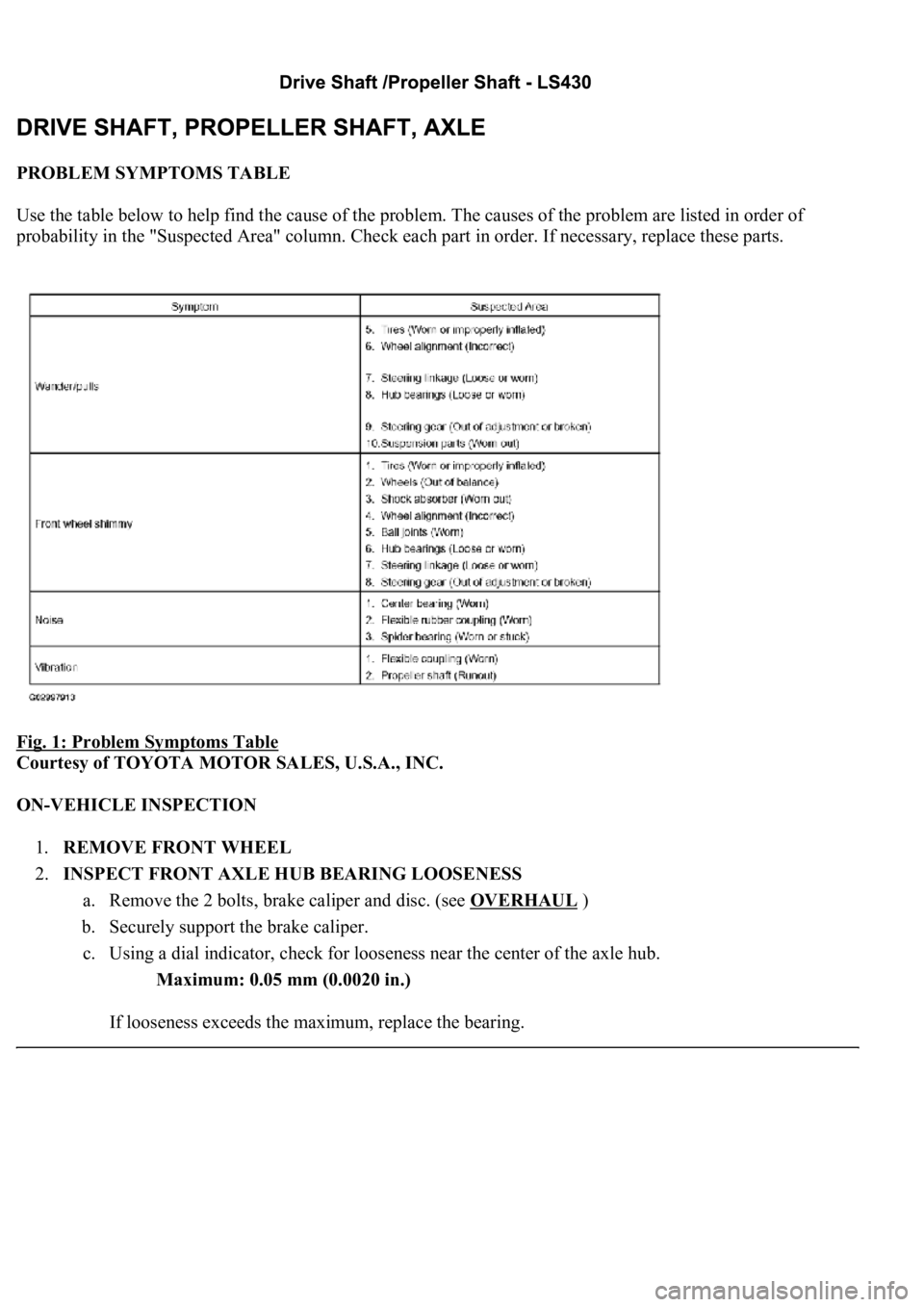
PROBLEM SYMPTOMS TABLE
Use the table below to help find the cause of the problem. The causes of the problem are listed in order of
probability in the "Suspected Area" column. Check each part in order. If necessary, replace these parts.
Fig. 1: Problem Symptoms Table
Courtesy of TOYOTA MOTOR SALES, U.S.A., INC.
ON-VEHICLE INSPECTION
1.REMOVE FRONT WHEEL
2.INSPECT FRONT AXLE HUB BEARING LOOSENESS
a. Remove the 2 bolts, brake caliper and disc. (see OVERHAUL
)
b. Securely support the brake caliper.
c. Using a dial indicator, check for looseness near the center of the axle hub.
Maximum: 0.05 mm (0.0020 in.)
If looseness exceeds the maximum, replace the bearing.
Page 2307 of 4500
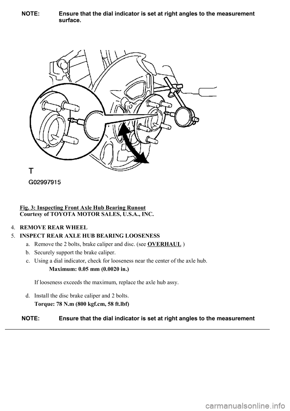
Fig. 3: Inspecting Front Axle Hub Bearing Runout
Courtesy of TOYOTA MOTOR SALES, U.S.A., INC.
4.REMOVE REAR WHEEL
5.INSPECT REAR AXLE HUB BEARING LOOSENESS
a. Remove the 2 bolts, brake caliper and disc. (see OVERHAUL
)
b. Securely support the brake caliper.
c. Using a dial indicator, check for looseness near the center of the axle hub.
Maximum: 0.05 mm (0.0020 in.)
If looseness exceeds the maximum, replace the axle hub assy.
d. Install the disc brake caliper and 2 bolts.
Torque: 78 N.m (800 kgf.cm, 58 ft.lbf)
Page 2352 of 4500
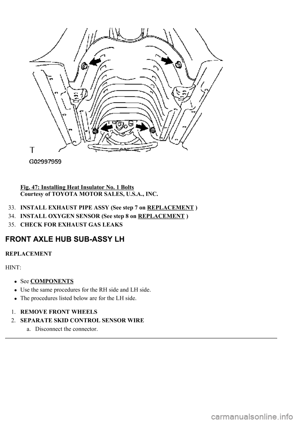
Fig. 47: Installing Heat Insulator No. 1 Bolts
Courtesy of TOYOTA MOTOR SALES, U.S.A., INC.
33.INSTALL EXHAUST PIPE ASSY (See step 7 on REPLACEMENT
)
34.INSTALL OXYGEN SENSOR (See step 8 on REPLACEMENT
)
35.CHECK FOR EXHAUST GAS LEAKS
REPLACEMENT
HINT:
See COMPONENTS
Use the same procedures for the RH side and LH side.
The procedures listed below are for the LH side.
1.REMOVE FRONT WHEELS
2.SEPARATE SKID CONTROL SENSOR WIRE
a. Disconnect the connector.