park LEXUS LS430 2003 Factory User Guide
[x] Cancel search | Manufacturer: LEXUS, Model Year: 2003, Model line: LS430, Model: LEXUS LS430 2003Pages: 4500, PDF Size: 87.45 MB
Page 836 of 4500
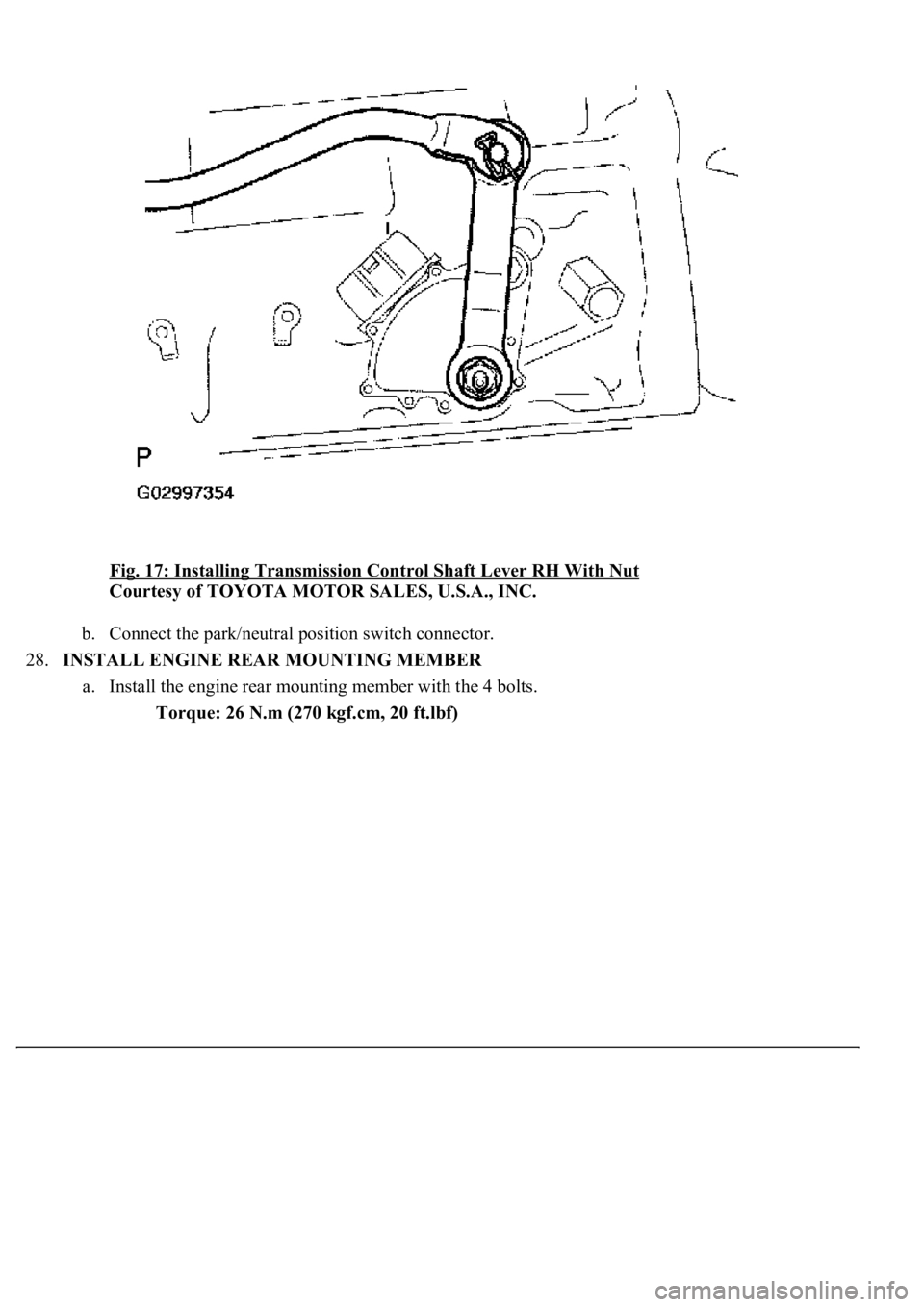
Fig. 17: Installing Transmission Control Shaft Lever RH With Nut
Courtesy of TOYOTA MOTOR SALES, U.S.A., INC.
b. Connect the park/neutral position switch connector.
28.INSTALL ENGINE REAR MOUNTING MEMBER
a. Install the engine rear mounting member with the 4 bolts.
Torque: 26 N.m (270 kgf.cm, 20 ft.lbf)
Page 838 of 4500
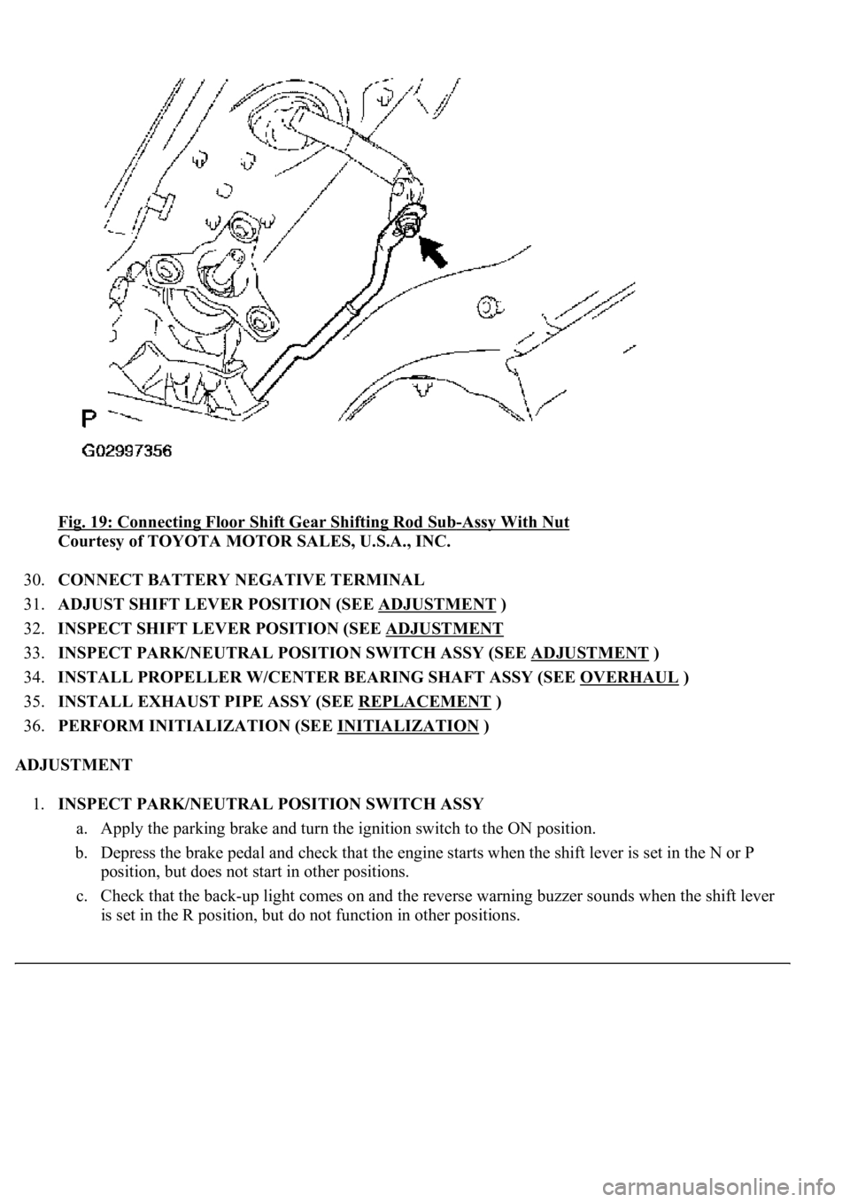
<0029004c004a001100030014001c001d00030026005200510051004800460057004c0051004a00030029004f00520052005500030036004b004c004900570003002a00480044005500030036004b004c00490057004c0051004a0003003500520047000300
3600580045[-Assy With Nut
Courtesy of TOYOTA MOTOR SALES, U.S.A., INC.
30.CONNECT BATTERY NEGATIVE TERMINAL
31.ADJUST SHIFT LEVER POSITION (SEE ADJUSTMENT
)
32.INSPECT SHIFT LEVER POSITION (SEE ADJUSTMENT
33.INSPECT PARK/NEUTRAL POSITION SWITCH ASSY (SEE ADJUSTMENT
)
34.INSTALL PROPELLER W/CENTER BEARING SHAFT ASSY (SEE OVERHAUL
)
35.INSTALL EXHAUST PIPE ASSY (SEE REPLACEMENT
)
36.PERFORM INITIALIZATION (SEE INITIALIZATION
)
ADJUSTMENT
1.INSPECT PARK/NEUTRAL POSITION SWITCH ASSY
a. Apply the parking brake and turn the ignition switch to the ON position.
b. Depress the brake pedal and check that the engine starts when the shift lever is set in the N or P
position, but does not start in other positions.
c. Check that the back-up light comes on and the reverse warning buzzer sounds when the shift lever
is set in the R position, but do not function in other positions.
Page 839 of 4500
If a failure is found, check the park/neutral position switch for continuity.
2.ADJUST PARK/NEUTRAL POSITION SWITCH ASSY
a. Loosen the bolt of the park/neutral position switch and move the shift lever to the N position.
b. Align the groove and the neutral basic line.
c. Hold the switch in position and tighten the bolt.
Torque: 13.0 N.m (130 kgf.cm, 9 ft.lbf)
d. After adjustment, perform the inspection described in step 1.
Fig. 20: Aligning Groove And Neutral Basic Line
Courtesy of TOYOTA MOTOR SALES, U.S.A., INC.
REPLACEMENT
1.REMOVE TRANSMISSION REVOLUTION SENSOR (NC0 SENSOR)
a. Disconnect the transmission revolution sensor connector.
b. Remove the bolt and transmission revolution sensor.
Page 849 of 4500
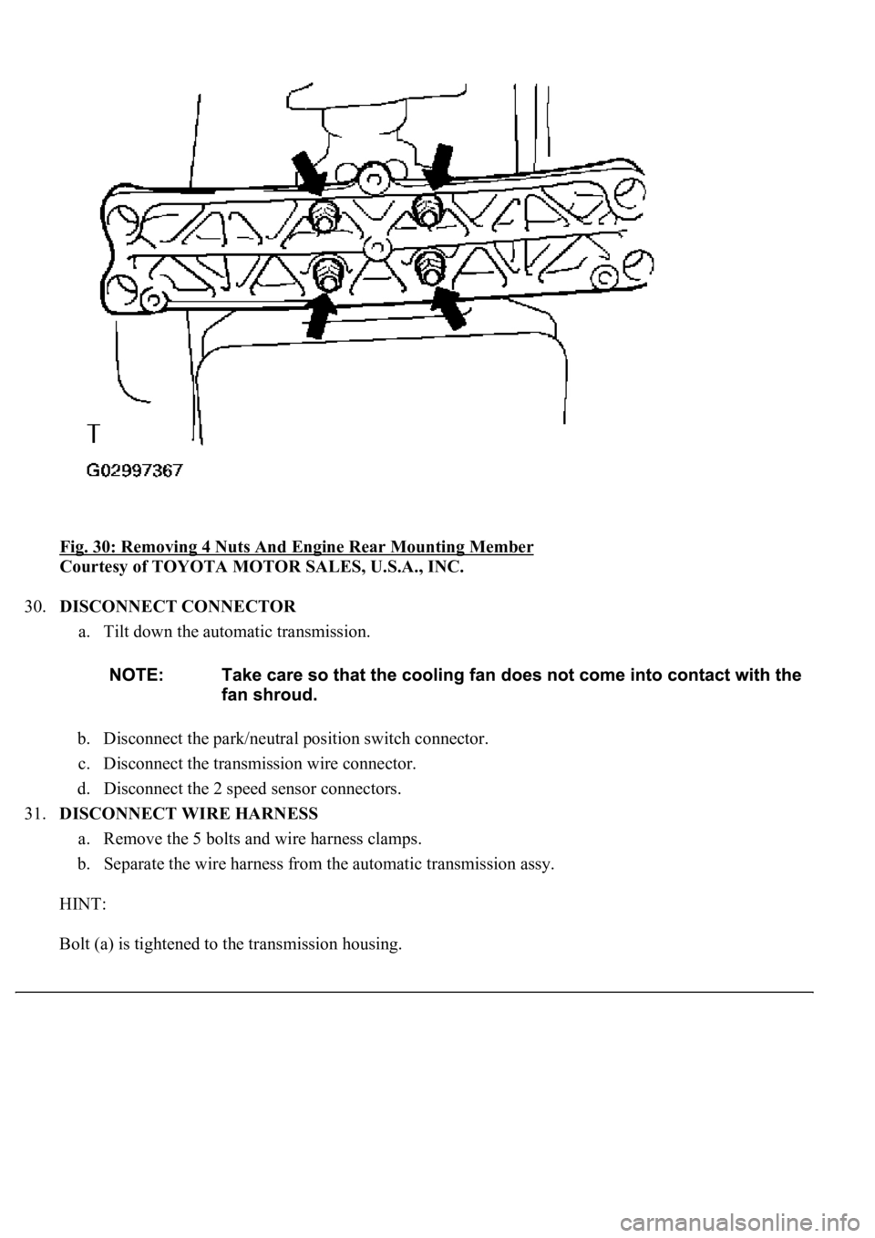
Fig. 30: Removing 4 Nuts And Engine Rear Mounting Member
Courtesy of TOYOTA MOTOR SALES, U.S.A., INC.
30.DISCONNECT CONNECTOR
a. Tilt down the automatic transmission.
b. Disconnect the park/neutral position switch connector.
c. Disconnect the transmission wire connector.
d. Disconnect the 2 speed sensor connectors.
31.DISCONNECT WIRE HARNESS
a. Remove the 5 bolts and wire harness clamps.
b. Separate the wire harness from the automatic transmission assy.
HINT:
Bolt (a) is ti
ghtened to the transmission housing.
Page 960 of 4500
Fig. 135: Installing Floor Shift Gear Shifting Rod Sub-Assy With Nut
Courtesy of TOYOTA MOTOR SALES, U.S.A., INC.
51.CONNECT BATTERY NEGATIVE TERMINAL
52.ADJUST SHIFT LEVER POSITION (SEE ADJUSTMENT
)
53.INSPECT SHIFT LEVER POSITION (SEE ADJUSTMENT
)
54.PERFORM INITIALIZATION (SEE INITIALIZATION
)
ADJUSTMENT
1.INSPECT SHIFT LEVER POSITION
a. When shifting from the P to R position with the ignition switch on and brake pedal depressed, make
sure that the shift lever moves smoothly and moves correctly into position.
b. Start the engine and make sure that the vehicle moves forward when shifting from the N to D
position and moves rearward when shifting to the R position.
If operation cannot be done as specified, inspect the park/neutral position switch assy and check the shift
lever assy installation condition.
2.ADJUST SHIFT LEVER POSITION
a. Remove the nut and disconnect the shiftin
g rod from the connecting rod swivel.
Page 984 of 4500
a. Release the parking brake pedal.
b. With the engine running, depress the pedal and measure the pedal reserve distance, as shown in the
illustration.
Pedal reserve distance from asphalt sheet at 490 N (50 kgf, 110.2 lbf): More than 105 mm (4.13 in.)
If incorrect, troubleshoot the brake system.
Fig. 19: Checking Pedal Reserve Distance
Courtesy of TOYOTA MOTOR SALES, U.S.A., INC.
19.INSTALL FLOOR CARPET ASSY FRONT
20.INSTALL FR DOOR SCUFF PLATE LH (SEE REPLACEMENT
)
21.INSTALL INSTRUMENT PANEL UNDER COVER SUB-ASSY NO.2 (SEE REPLACEMENT
)
22.INSTALL INSTRUMENT PANEL UNDER SAFETY PAD SUB-ASSY NO.1 (SEE
REPLACEMENT
)
Page 1067 of 4500
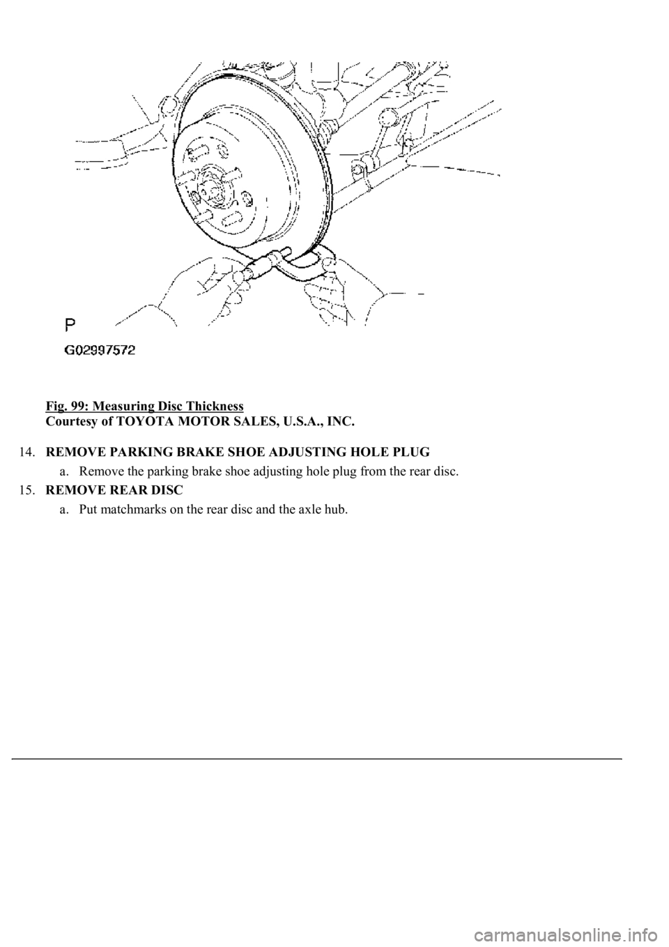
Fig. 99: Measuring Disc Thickness
Courtesy of TOYOTA MOTOR SALES, U.S.A., INC.
14.REMOVE PARKING BRAKE SHOE ADJUSTING HOLE PLUG
a. Remove the parking brake shoe adjusting hole plug from the rear disc.
15.REMOVE REAR DISC
a. Put matchmarks on the rear disc and the axle hub.
Page 1068 of 4500
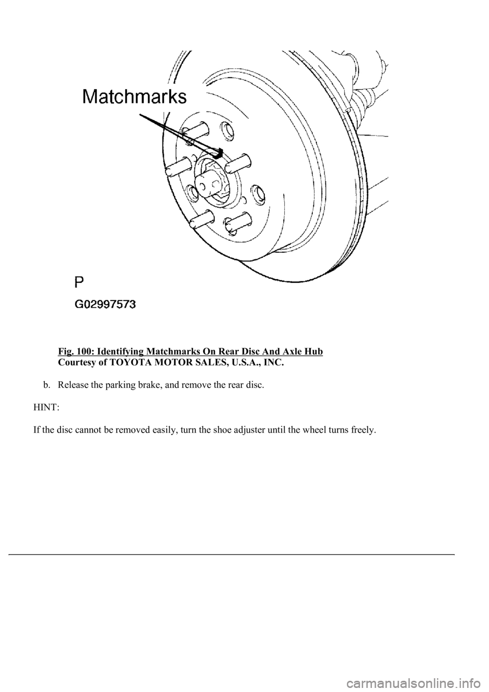
Fig. 100: Identifying Matchmarks On Rear Disc And Axle Hub
Courtesy of TOYOTA MOTOR SALES, U.S.A., INC.
b. Release the parking brake, and remove the rear disc.
HINT:
If the disc cannot be removed easil
y, turn the shoe adjuster until the wheel turns freely.
Page 1069 of 4500
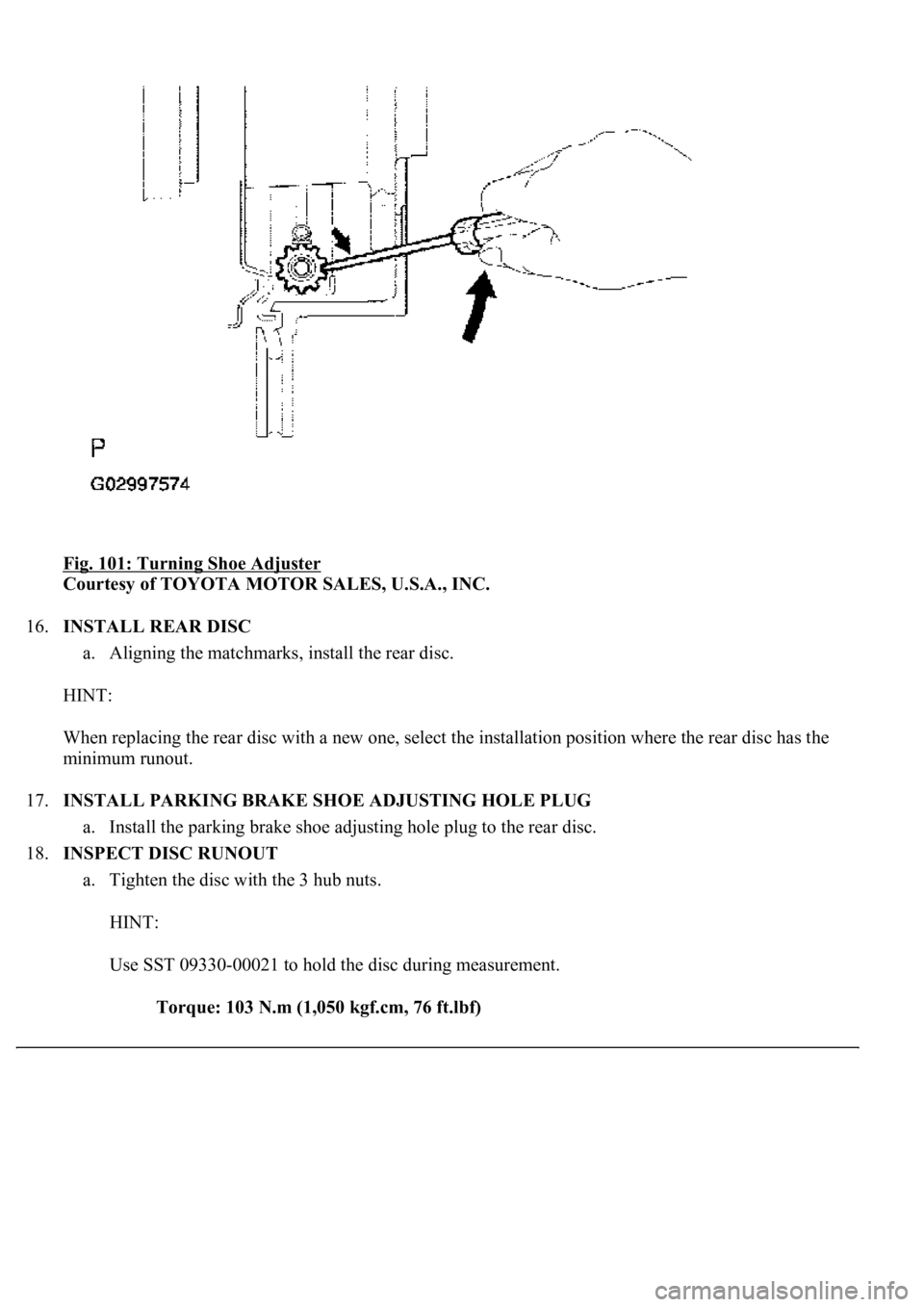
Fig. 101: Turning Shoe Adjuster
Courtesy of TOYOTA MOTOR SALES, U.S.A., INC.
16.INSTALL REAR DISC
a. Aligning the matchmarks, install the rear disc.
HINT:
When replacing the rear disc with a new one, select the installation position where the rear disc has the
minimum runout.
17.INSTALL PARKING BRAKE SHOE ADJUSTING HOLE PLUG
a. Install the parking brake shoe adjusting hole plug to the rear disc.
18.INSPECT DISC RUNOUT
a. Tighten the disc with the 3 hub nuts.
HINT:
Use SST 09330-00021 to hold the disc during measurement.
Torque: 103 N.m (1,050 kgf.cm, 76 ft.lbf)
Page 1071 of 4500
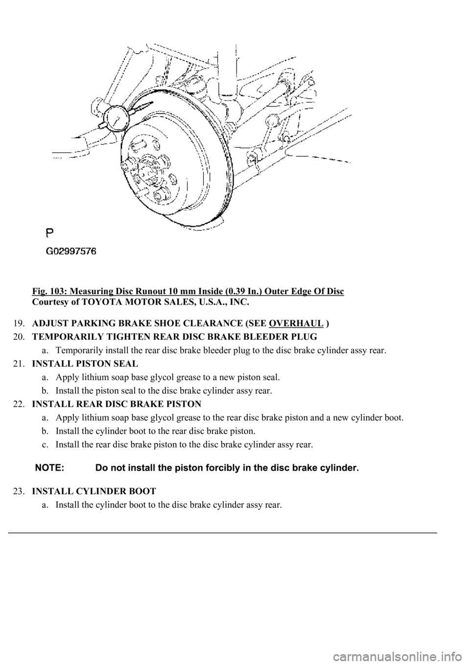
Fig. 103: Measuring Disc Runout 10 mm Inside (0.39 In.) Outer Edge Of Disc
Courtesy of TOYOTA MOTOR SALES, U.S.A., INC.
19.ADJUST PARKING BRAKE SHOE CLEARANCE (SEE OVERHAUL
)
20.TEMPORARILY TIGHTEN REAR DISC BRAKE BLEEDER PLUG
a. Temporarily install the rear disc brake bleeder plug to the disc brake cylinder assy rear.
21.INSTALL PISTON SEAL
a. Apply lithium soap base glycol grease to a new piston seal.
b. Install the piston seal to the disc brake cylinder assy rear.
22.INSTALL REAR DISC BRAKE PISTON
a. Apply lithium soap base glycol grease to the rear disc brake piston and a new cylinder boot.
b. Install the cylinder boot to the rear disc brake piston.
c. Install the rear disc brake piston to the disc brake cylinder assy rear.
23.INSTALL CYLINDER BOOT
a. Install the cylinder boot to the disc brake cylinder assy rear.