LEXUS LS430 2003 Factory User Guide
LS430 2003
LEXUS
LEXUS
https://www.carmanualsonline.info/img/36/57050/w960_57050-0.png
LEXUS LS430 2003 Factory User Guide
Page 2408 of 4500
42.ADJUST PARKING BRAKE PEDAL TRAVEL (See step 5 on ADJUSTMENT )
43.INSTALL SPEED SENSOR REAR LH
a. Install the speed sensor with the bolt.
Torque: 8.0 N.m (82 kgf.cm, 71 in.lbf)
44.INSTALL REAR DISC (See step 16 on OVERHAUL
)
45.ADJUST PARKING BRAKE SHOE CLEARANCE (See step 21 on OVERHAUL
)
46.INSTALL REAR DISC BRAKE CALIPER ASSY LH (See step 20 on REPLACEMENT
)
47.INSTALL REAR AXLE SHAFT NUT (See REPLACEMENT
)
48.INSPECT AXLE HUB BEARING LOOSENESS (See ON
-VEHICLE INSPECTION )
49.INSPECT AXLE HUB BEARING RUNOUT (See ON
-VEHICLE INSPECTION )
50.STABILIZE SUSPENSION (See step 23 on REPLACEMENT
)
51.FULLY TIGHTEN SHOCK ABSORBER ASSY REAR LH
a. Fully tighten the shock absorber assy LH with the new nut.
Torque: 70 N.m (714 kgf.cm, 52 ft.lbf)
52.INSTALL REAR TIRE
Torque: 103 N.m (1,050 kgf.cm, 76 ft.lbf)
53.ADJUST VEHICLE HEIGHT (W/ AIR SUSPENSION) (See ON
-VEHICLE INSPECTION )
54.INSPECT HEADLIGHT AIM ONLY (See ADJUSTMENT
)
55.INSPECT AND ADJUST REAR WHEEL ALIGNMENT (See ADJUSTMENT
)
56.CHECK ABS SPEED SENSOR SIGNAL (See TEST MODE PROCEDURE
)
REPLACEMENT
HINT:
See COMPONENTS
Use the same procedures for the RH side and LH side.
The procedures listed below are for the LH side.
1.REMOVE REAR TIRE
2.REMOVE REAR DISC BRAKE CALIPER ASSY LH (See REPLACEMENT
)
3.REMOVE REAR DISC (See step 15 on OVERHAUL
)
4.REMOVE REAR AXLE LH HUB BOLT
a. Using SST and a screwdriver or an equivalent to hold, remove the hub bolt.
SST 09628-10011
Page 3314 of 4500
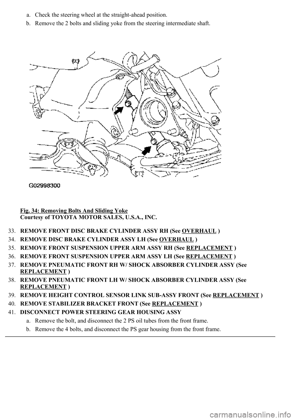
a. Check the steering wheel at the straight-ahead position.
b. Remove the 2 bolts and sliding yoke from the steering intermediate shaft.
Fig. 34: Removing Bolts And Sliding Yoke
Courtesy of TOYOTA MOTOR SALES, U.S.A., INC.
33.REMOVE FRONT DISC BRAKE CYLINDER ASSY RH (See OVERHAUL
)
34.REMOVE DISC BRAKE CYLINDER ASSY LH (See OVERHAUL
)
35.REMOVE FRONT SUSPENSION UPPER ARM ASSY RH (See REPLACEMENT
)
36.REMOVE FRONT SUSPENSION UPPER ARM ASSY LH (See REPLACEMENT
)
37.REMOVE PNEUMATIC FRONT RH W/ SHOCK ABSORBER CYLINDER ASSY (See
REPLACEMENT
)
38.REMOVE PNEUMATIC FRONT LH W/ SHOCK ABSORBER CYLINDER ASSY (See
REPLACEMENT
)
39.REMOVE HEIGHT CONTROL SENSOR LINK SUB-ASSY FRONT (See REPLACEMENT
)
40.REMOVE STABILIZER BRACKET FRONT (See REPLACEMENT
)
41.DISCONNECT POWER STEERING GEAR HOUSING ASSY
a. Remove the bolt, and disconnect the 2 PS oil tubes from the front frame.
b. Remove the 4 bolts, and disconnect the PS gear housing from the front frame.
Page 3357 of 4500
Fig. 77: Installing Power Steering Gear Housing Assy
Courtesy of TOYOTA MOTOR SALES, U.S.A., INC.
114.INSTALL HEIGHT CONTROL SENSOR LINK SUB-ASSY FRONT (See REPLACEMENT
)
115.INSTALL PNEUMATIC FRONT RH W/SHOCK ABSORBER CYLINDER ASSY (See
REPLACEMENT
)
116.INSTALL PNEUMATIC FRONT LH W/SHOCK ABSORBER CYLINDER ASSY (See
REPLACEMENT
)
117.INSTALL FRONT SUSPENSION UPPER ARM ASSY RH (See REPLACEMENT
)
118.INSTALL FRONT SUSPENSION UPPER ARM ASSY LH (See REPLACEMENT
)
119.INSTALL FRONT DISC BRAKE CYLINDER ASSY RH (See OVERHAUL
)
120.INSTALL DISC BRAKE CYLINDER ASSY LH (See OVERHAUL
)
121.INSTALL STEERING SLIDING W/ SHAFT YOKE SUB-ASSY
a. Tighten the 2 bolts for sliding yoke.
Torque: 35 N.m (357 kgf.cm, 26 ft.lbf)
Page 4009 of 4500
REPLACEMENT
HINT:
Use the same procedures for the RH side and LH side.
The procedures listed below are for the LH side.
1.REMOVE FRONT WHEELS
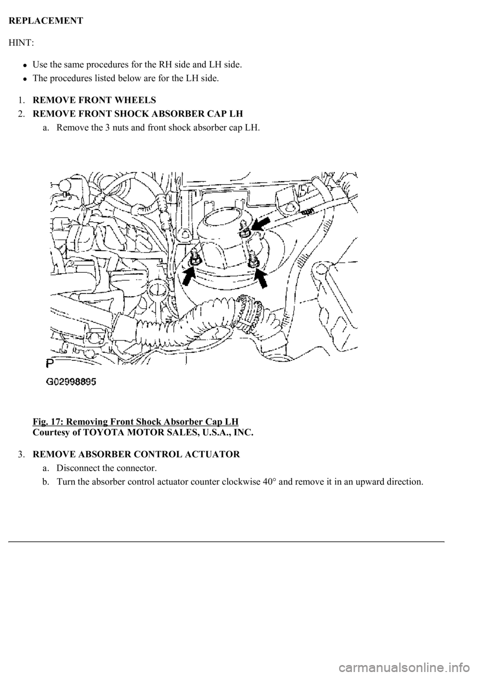
2.REMOVE FRONT SHOCK ABSORBER CAP LH
a. Remove the 3 nuts and front shock absorber cap LH.
Fig. 17: Removing Front Shock Absorber Cap LH
Courtesy of TOYOTA MOTOR SALES, U.S.A., INC.
3.REMOVE ABSORBER CONTROL ACTUATOR
a. Disconnect the connector.
b. Turn the absorber control actuator counter clockwise 40° and remove it in an upward direction.
Page 4011 of 4500
Fig. 19: Separating Front Stabilizer Link Assy LH
Courtesy of TOYOTA MOTOR SALES, U.S.A., INC.
6.REMOVE PNEUMATIC FRONT LH W/SHOCK ABSORBER CYLINDER ASSY
a. Remove the cover and disconnect the connector No. 1 (see PRECAUTION
).
b. Using SST, disconnect the air tube from the pneumatic front LH w/shock absorber cylinder assy.
SST 09730-00010
Page 4012 of 4500
Fig. 20: Disconnecting Air Tube From Pneumatic Front LH W/Shock Absorber Cylinder
Assy
Courtesy of TOYOTA MOTOR SALES, U.S.A., INC.
c. Remove the pneumatic front LH w/shock absorber cylinder assy lower side nut.
Page 4013 of 4500
Fig. 21: Removing Pneumatic Front LH W/Shock Absorber Cylinder Assy Lower Side Nut
Courtesy of TOYOTA MOTOR SALES, U.S.A., INC.
d. Remove the 3 nuts on the upper side of the pneumatic front LH w/shock absorber c
ylinder assy.
Page 4014 of 4500
Fig. 22: Removing Nuts On Upper Side Of Pneumatic Front LH W/Shock Absorber Cylinder
Assy
Courtesy of TOYOTA MOTOR SALES, U.S.A., INC.
e. Let it down slowly to remove the bolt and the pneumatic front LH w/shock absorber cylinder assy
and suspension support.
7.REMOVE O-RING
a. Remove the connector No. 2 and 2 O-rings.
8.INSPECT PNEUMATIC FRONT LH W/SHOCK ABSORBER CYLINDER ASSY
a. Inspect pneumatic cylinder assy operation.
1. Compress and expand the pneumatic front LH w/shock absorber cylinder assy 4 times or
more.
2. Check that there is no abnormal resistance or unusual operation sounds.
If there is any abnormality, replace the pneumatic front LH w/shock absorber cylinder assy with a
new one.
Page 4016 of 4500
Fig. 24: Checking Difference In Damping Force
Courtesy of TOYOTA MOTOR SALES, U.S.A., INC.
9.INSTALL O-RING
a. Install the 2 O-rings and connector No. 2.
10.TEMPORARILY TIGHTEN PNEUMATIC FRONT LH W/SHOCK ABSORBER CYLINDER
ASSY
a. Temporaril
y install the pneumatic front LH w/shock absorber cylinder assy with a bolt and a nut.
Page 4017 of 4500
Fig. 25: Installing Pneumatic Front LH W/Shock Absorber Cylinder Assy Temporarily
Courtesy of TOYOTA MOTOR SALES, U.S.A., INC.
b. Jack up the suspension lower arm assy slowly using a wood block to avoid damage.
c. Install the suspension support and pneumatic front LH w/shock absorber cylinder with 3 nuts.
Torque: 58 N.m (590 kgf.cm, 43 ft.lbf)