check engine light LEXUS LS430 2003 Factory Repair Manual
[x] Cancel search | Manufacturer: LEXUS, Model Year: 2003, Model line: LS430, Model: LEXUS LS430 2003Pages: 4500, PDF Size: 87.45 MB
Page 29 of 4500

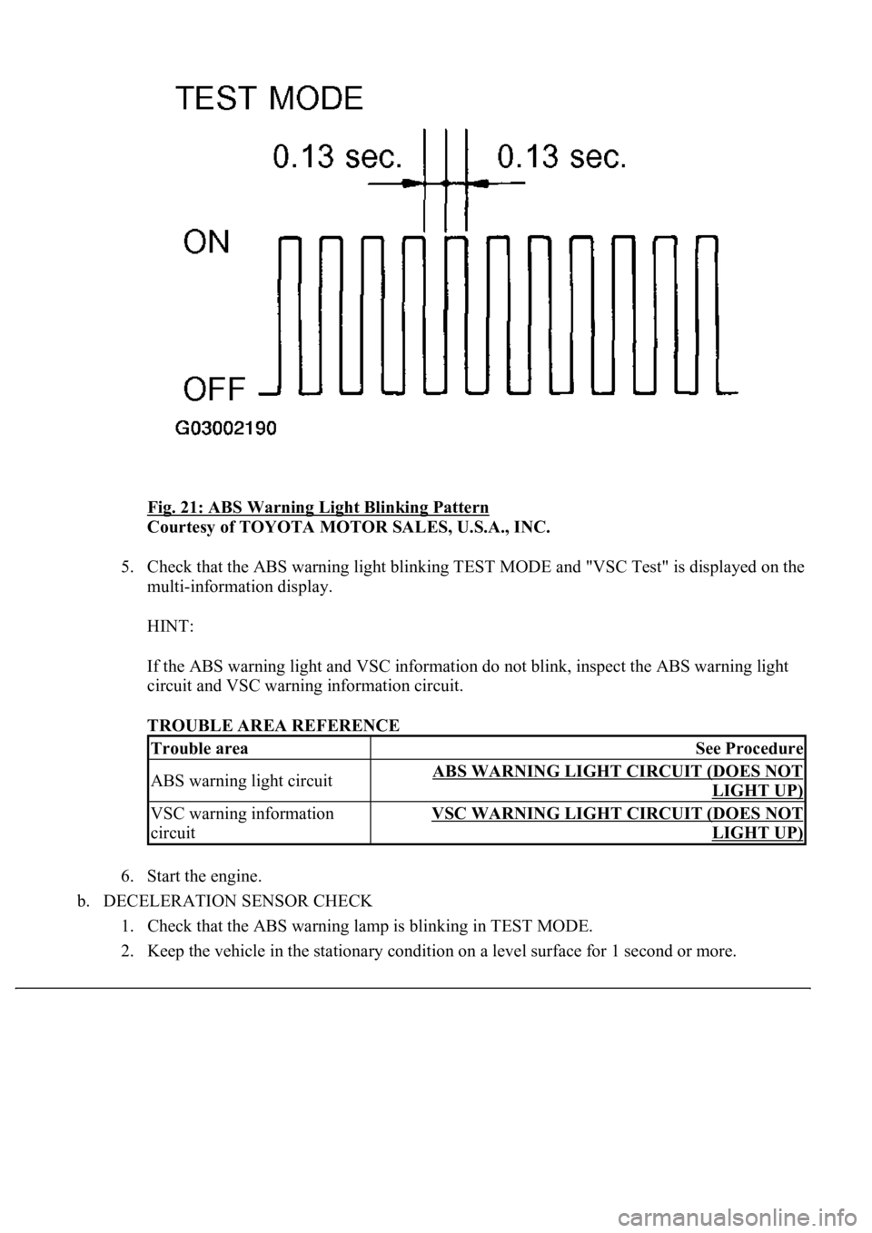
Fig. 21: ABS Warning Light Blinking Pattern
Courtesy of TOYOTA MOTOR SALES, U.S.A., INC.
5. Check that the ABS warning light blinking TEST MODE and "VSC Test" is displayed on the
multi-information display.
HINT:
If the ABS warning light and VSC information do not blink, inspect the ABS warning light
circuit and VSC warning information circuit.
TROUBLE AREA REFERENCE
6. Start the engine.
b. DECELERATION SENSOR CHECK
1. Check that the ABS warning lamp is blinking in TEST MODE.
2. Keep the vehicle in the stationar
y<00030046005200510047004c0057004c00520051000300520051000300440003004f004800590048004f0003005600580055004900440046004800030049005200550003001400030056004800460052005100470003005200550003005000520055004800
110003[
Trouble areaSee Procedure
ABS warning light circuitABS WARNING LIGHT CIRCUIT (DOES NOT
LIGHT UP)
VSC warning information
circuitVSC WARNING LIGHT CIRCUIT (DOES NOT
LIGHT UP)
Page 30 of 4500

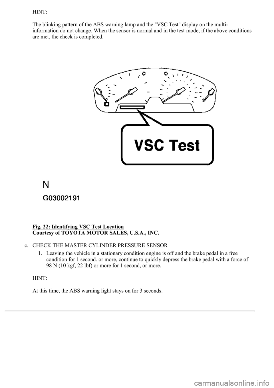
HINT:
The blinking pattern of the ABS warning lamp and the "VSC Test" display on the multi-
information do not change. When the sensor is normal and in the test mode, if the above conditions
are met, the check is completed.
Fig. 22: Identifying VSC Test Location
Courtesy of TOYOTA MOTOR SALES, U.S.A., INC.
c. CHECK THE MASTER CYLINDER PRESSURE SENSOR
1. Leaving the vehicle in a stationary condition engine is off and the brake pedal in a free
condition for 1 second. or more, continue to quickly depress the brake pedal with a force of
98 N (10 kgf, 22 lbf) or more for 1 second, or more.
HINT:
At this time, the ABS warnin
g light stays on for 3 seconds.
Page 55 of 4500

HINT:
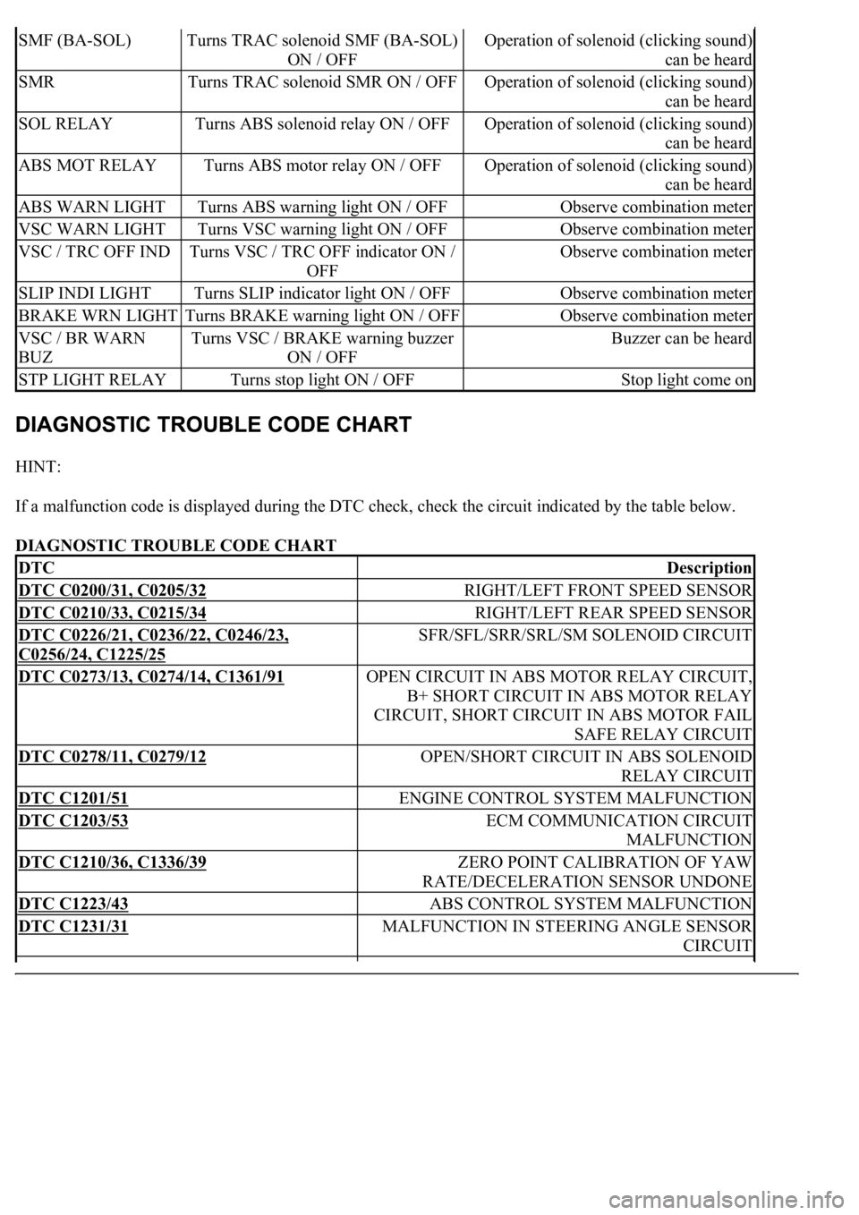
If a malfunction code is displayed during the DTC check, check the circuit indicated by the table below.
DIAGNOSTIC TROUBLE CODE CHART
SMF (BA-SOL)Turns TRAC solenoid SMF (BA-SOL)
ON / OFFOperation of solenoid (clicking sound)
can be heard
SMRTurns TRAC solenoid SMR ON / OFFOperation of solenoid (clicking sound)
can be heard
SOL RELAYTurns ABS solenoid relay ON / OFFOperation of solenoid (clicking sound)
can be heard
ABS MOT RELAYTurns ABS motor relay ON / OFFOperation of solenoid (clicking sound)
can be heard
ABS WARN LIGHTTurns ABS warning light ON / OFFObserve combination meter
VSC WARN LIGHTTurns VSC warning light ON / OFFObserve combination meter
VSC / TRC OFF INDTurns VSC / TRC OFF indicator ON /
OFFObserve combination meter
SLIP INDI LIGHTTurns SLIP indicator light ON / OFFObserve combination meter
BRAKE WRN LIGHTTurns BRAKE warning light ON / OFFObserve combination meter
VSC / BR WARN
BUZTurns VSC / BRAKE warning buzzer
ON / OFFBuzzer can be heard
STP LIGHT RELAYTurns stop light ON / OFFStop light come on
DTCDescription
DTC C0200/31, C0205/32RIGHT/LEFT FRONT SPEED SENSOR
DTC C0210/33, C0215/34RIGHT/LEFT REAR SPEED SENSOR
DTC C0226/21, C0236/22, C0246/23,
C0256/24, C1225/25
SFR/SFL/SRR/SRL/SM SOLENOID CIRCUIT
DTC C0273/13, C0274/14, C1361/91OPEN CIRCUIT IN ABS MOTOR RELAY CIRCUIT,
B+ SHORT CIRCUIT IN ABS MOTOR RELAY
CIRCUIT, SHORT CIRCUIT IN ABS MOTOR FAIL
SAFE RELAY CIRCUIT
DTC C0278/11, C0279/12OPEN/SHORT CIRCUIT IN ABS SOLENOID
RELAY CIRCUIT
DTC C1201/51ENGINE CONTROL SYSTEM MALFUNCTION
DTC C1203/53ECM COMMUNICATION CIRCUIT
MALFUNCTION
DTC C1210/36, C1336/39ZERO POINT CALIBRATION OF YAW
RATE/DECELERATION SENSOR UNDONE
DTC C1223/43ABS CONTROL SYSTEM MALFUNCTION
DTC C1231/31MALFUNCTION IN STEERING ANGLE SENSOR
CIRCUIT
Page 154 of 4500

a. Is the DTC output for CAN communication system?
Result:
DTC OUTPUT DESCRIPTION
B: REPAIR CAN COMMUNICATION SYSTEM (SEE PRECAUTION
)
A: Go to next step
2.INSPECT MULTIPLEX COMMUNICATION SYSTEM
a. Is the DTC output for Multiplex communication system?
Result:
DTC OUTPUT DESCRIPTION
B: REPAIR MULTIPLEX COMMUNICATION SYSTEM (SEE DIAGNOSTIC TROUBLE
CODE CHART )
A: Go to next step
3.INSPECT ABS WARNING LIGHT
a. Connect the hand-held tester to the DLC3 and start the engine.
b. Select the item "ABS WARN LIGHT" in the ACTIVE TEST and operate the ABS warning light on
the hand-held tester.
VEHICLE CONDITION / TEST DETAILS
c. Check that "ON" and "OFF" of the ABS warning light can be shown on the combination meter by
the hand-held tester.
Standard:
Turn the ABS warning light ON or OFF in accordance with the hand-held tester.
NG: CHECK AND REPAIR ABS WARNING LIGHT CIRCUIT
OK: REPLACE ABS & TRACTION ACTUATOR ASSY (SEE REPLACEMENT
)
DTC is not outputA
DTC is outputB
DTC is not outputA
DTC is outputB
ItemVehicle Condition / Test DetailsDiagnostic Note
ABS WARN LIGHTTurns ABS warning light ON / OFFObserve combination meter
Page 161 of 4500

Result:
DTC OUTPUT DESCRIPTION
B: REPAIR CAN COMMUNICATION SYSTEM (SEE PRECAUTION
)
A: Go to next step
2.INSPECT MULTIPLEX COMMUNICATION SYSTEM
a. Is the DTC output for Multiplex communication system?
Result:
DTC OUTPUT DESCRIPTION
B: REPAIR MULTIPLEX COMMUNICATION SYSTEM (SEE DIAGNOSTIC TROUBLE
CODE CHART )
A: Go to next step
3.CHECK MULTI INFORMATION DISPLAY (VSC WARNING)
a. Connect the hand-held tester to the DLC3 and start the engine.
b. Select the item "VSC WARN LIGHT" in the ACTIVE TEST and operate the VSC warning light on
the hand-held tester.
VEHICLE CONDITION / TEST DETAILS
c. Check that "ON" and "OFF" of the VSC warning light are indicated on the combination meter
when using the hand-held tester.
OK: Go to next step
Turn the VSC warning light ON or OFF in accordance with the hand-held tester.
NG: CHECK AND REPAIR VSC WARNING LIGHT CIRCUIT
OK: REPLACE ABS & TRACTION ACTUATOR ASSY (SEE REPLACEMENT
)
DTC is not outputA
DTC is outputB
DTC is not outputA
DTC is outputB
ItemVehicle Condition / Test DetailsDiagnostic Note
VSC WARN LIGHTTurns VSC warning light ON / OFFObserve combination meter
Page 165 of 4500

INSPECTION PROCEDURE
HINT:
When releasing the parking brake, set the chocks to hold the vehicle for safety.
Check that "Brake Wear" does not appear on the multi-information display.
If it appears, check that brake pad thickness and replace the pad as necessary.
1.CHECK BRAKE FLUID LEVEL IN RESERVOIR
a. Check that the brake fluid level is proper.
OK: Go to next step
Brake fluid level is proper.
NG: ADD BRAKE FLUID
OK: Go to next step
2.CHECK DTC
a. Are the DTC recorded for ABS, VSC, CAN and/or Multiplex communication system?
OK: Go to next step
DTC OUTPUT DESCRIPTION
B: REPAIR CIRCUIT INDICATED BY OUTPUT CODE
A: Go to next step
3.INSPECT BRAKE WARNING LIGHT
a. Connect the hand-held tester to the DLC3.
b. Start the engine.
c. Select the item "BRAKE WARN LIGHT" in the ACTIVE TEST and operate the BRAKE warning
light on the hand-held tester.
VEHICLE CONDITION / TEST DETAILS
d. Check that "ON" and "OFF" of the BRAKE warning light are indicated on the combination meter
when usin
g the hand-held tester.
DTC is not outputA
DTC is outputB
ItemVehicle Condition / Test DetailsDiagnostic Note
BRAKE WRN LIGHTTurns BRAKE warning light ON / OFFObserve combination meter
Page 176 of 4500

1.PERFORM ACTIVE TEST BY HAND-HELD TESTER (TRAC OFF INDICATOR LIGHT)
a. Connect the hand-held tester to the DLC3.
b. Start the engine.
c. Select the item "TRAC OFF LIGHT" in the ACTIVE TEST and operate the TRAC OFF indicator
light on the hand-held tester.
VEHICLE CONDITION / TEST DETAILS
d. Check that "ON" and "OFF" of the TRAC OFF indicator light are indicated on the combination
meter when using the hand-held tester.
OK: Go to next step
Turn the TRAC OFF indicator light on or off in accordance with the hand-held tester.
NG: Go to step 5
OK: Go to next step
2.INSPECT MULTIPLEX COMMUNICATION SYSTEM
a. Is the DTC output for Multiplex communication system?
Result:
DTC OUTPUT DESCRIPTION
B: REPAIR MULTIPLEX COMMUNICATION SYSTEM (SEE DIAGNOSTIC TROUBLE
CODE CHART )
A: Go to next step
3.INSPECT CAN COMMUNICATION SYSTEM
a. Is the DTC output for CAN communication system?
Result:
DTC OUTPUT DESCRIPTION
ItemVehicle Condition / Test DetailsDiagnostic Note
VSC / TRAC OFF INDTurns VSC / TRAC OFF indicator ON / OFFObserve combination meter
DTC is not outputA
DTC is outputB
DTC is not outputA
DTC is outputB
Page 183 of 4500

a. Connect the hand-held tester to the DLC3.
b. Start the engine.
c. Select the item "SLIP INDI LIGHT" in the ACTIVE TEST and operate the SLIP indicator light on
the hand-held tester.
VEHICLE CONDITION / TEST DETAILS
d. Check that "ON" and "OFF" of the SLIP indicator light are indicated on the combination meter
when using the hand-held tester.
OK: Go to next step
Turn the SLIP indicator light on or off in accordance with the hand-held tester.
NG: Go to step 2
OK: REPLACE ABS & TRACTION ACTUATOR ASSY (SEE REPLACEMENT
)
2.INSPECT MULTIPLEX COMMUNICATION SYSTEM
a. Is the DTC output for Multiplex communication system?
Result:
DTC OUTPUT DESCRIPTION
B: REPAIR MULTIPLEX COMMUNICATION SYSTEM (SEE DIAGNOSTIC TROUBLE
CODE CHART )
A: Go to next step
3.INSPECT CAN COMMUNICATION SYSTEM
a. Is the DTC output for CAN communication system?
Result:
DTC OUTPUT DESCRIPTION
ItemVehicle Condition / Test DetailsDiagnostic Note
SLIP INDI LIGHTTurns SLIP indicator light ON / OFFObserve combination meter
DTC is not outputA
DTC is outputB
DTC is not outputA
Page 838 of 4500

<0029004c004a001100030014001c001d00030026005200510051004800460057004c0051004a00030029004f00520052005500030036004b004c004900570003002a00480044005500030036004b004c00490057004c0051004a0003003500520047000300
3600580045[-Assy With Nut
Courtesy of TOYOTA MOTOR SALES, U.S.A., INC.
30.CONNECT BATTERY NEGATIVE TERMINAL
31.ADJUST SHIFT LEVER POSITION (SEE ADJUSTMENT
)
32.INSPECT SHIFT LEVER POSITION (SEE ADJUSTMENT
33.INSPECT PARK/NEUTRAL POSITION SWITCH ASSY (SEE ADJUSTMENT
)
34.INSTALL PROPELLER W/CENTER BEARING SHAFT ASSY (SEE OVERHAUL
)
35.INSTALL EXHAUST PIPE ASSY (SEE REPLACEMENT
)
36.PERFORM INITIALIZATION (SEE INITIALIZATION
)
ADJUSTMENT
1.INSPECT PARK/NEUTRAL POSITION SWITCH ASSY
a. Apply the parking brake and turn the ignition switch to the ON position.
b. Depress the brake pedal and check that the engine starts when the shift lever is set in the N or P
position, but does not start in other positions.
c. Check that the back-up light comes on and the reverse warning buzzer sounds when the shift lever
is set in the R position, but do not function in other positions.
Page 1005 of 4500

34.CHECK AND ADJUST BRAKE PEDAL HEIGHT (SEE ON-VEHICLE INSPECTION )
35.CHECK PEDAL FREE PLAY (SEE ON
-VEHICLE INSPECTION )
36.CHECK PEDAL RESERVE DISTANCE (SEE ON
-VEHICLE INSPECTION )
37.INSTALL COMBINATION METER ASSY (SEE OVERHAUL
)
38.INSTALL INSTRUMENT CLUSTER FINISH PANEL (SEE REPLACEMENT
)
39.INSTALL INSTRUMENT PANEL UNDER COVER SUB-ASSY NO.2 (SEE REPLACEMENT
)
40.INSTALL INSTRUMENT PANEL AIR BAG ASSY LOWER NO.1 (SEE REPLACEMENT
)
41.INSTALL INSTRUMENT PANEL SAFETY PAD SUB-ASSY NO.1 (SEE REPLACEMENT
)
42.INSTALL OUTER MIRROR SWITCH ASSY
43.INSTALL COIN BOX ASSY
44.INSTALL INSTRUMENT PANEL UNDER COVER SUB-ASSY NO.1 (SEE REPLACEMENT
)
45.INSTALL INSTRUMENT CLUSTER FINISH PANEL CENTER LOWER
46.INSTALL INSTRUMENT CLUSTER FINISH PANEL END
47.INSTALL TURN SIGNAL SWITCH ASSY (SEE REPLACEMENT
)
48.INSTALL SPIRAL CABLE SUB-ASSY (SEE REPLACEMENT
)
49.INSTALL STEERING COLUMN COVER (SEE OVERHAUL
)
50.INSTALL STEERING WHEEL ASSY (SEE OVERHAUL
)
<00360036003700030013001c001c001800130010001800130013001400160003000b0013001c001c00180014001000130018001300140013000f00030013001c001c00180015001000130018001300140013000f00030013001c001c001800160010001300
18001300150013000f00030013001c001c0018001700100013[5021)
51.INSTALL HORN BUTTON ASSY (SEE OVERHAUL
)
52.INSTALL STEERING WHEEL COVER LOWER NO.2
53.INSTALL SWITCH & VOLUME CASE
54.CONNECT BATTERY NEGATIVE TERMINAL
55.INSPECT SRS WARNING LIGHT (SEE DIAGNOSIS SYSTEM
)
56.PERFORM INITIALIZATION (SEE PRECAUTION
)
OVERHAUL
1.REMOVE ENGINE ROOM SIDE COVER
2.SEPARATE ENGINE ROOM NO.3 R/B
a. Remove the bolt and separate the engine room No.3 R/B.
3.DRAIN BRAKE FLUID
a. Draw out fluid with syringe.
4.REMOVE BRAKE MASTER CYLINDER SUB-ASSY
a. Remove the clamp from the 2 brake tubes.