ESP LEXUS LS430 2003 Factory Owner's Manual
[x] Cancel search | Manufacturer: LEXUS, Model Year: 2003, Model line: LS430, Model: LEXUS LS430 2003Pages: 4500, PDF Size: 87.45 MB
Page 2341 of 4500

Fig. 36: Aligning Matchmarks
Courtesy of TOYOTA MOTOR SALES, U.S.A., INC.
f. If using a new propeller shaft (w/phasemarks):
Install the propeller shaft phasemarks and differential/transmission phasemarks so that their
respective alignment phasemarks match.
If the propeller shaft phasemarks and differential/transmission phasemarks do not align, install the
propeller shaft and differential alignment phasemarks as close together as possible.
g.If using a new propeller shaft (w/o phase marks): Install the propeller shaft.
Page 2450 of 4500
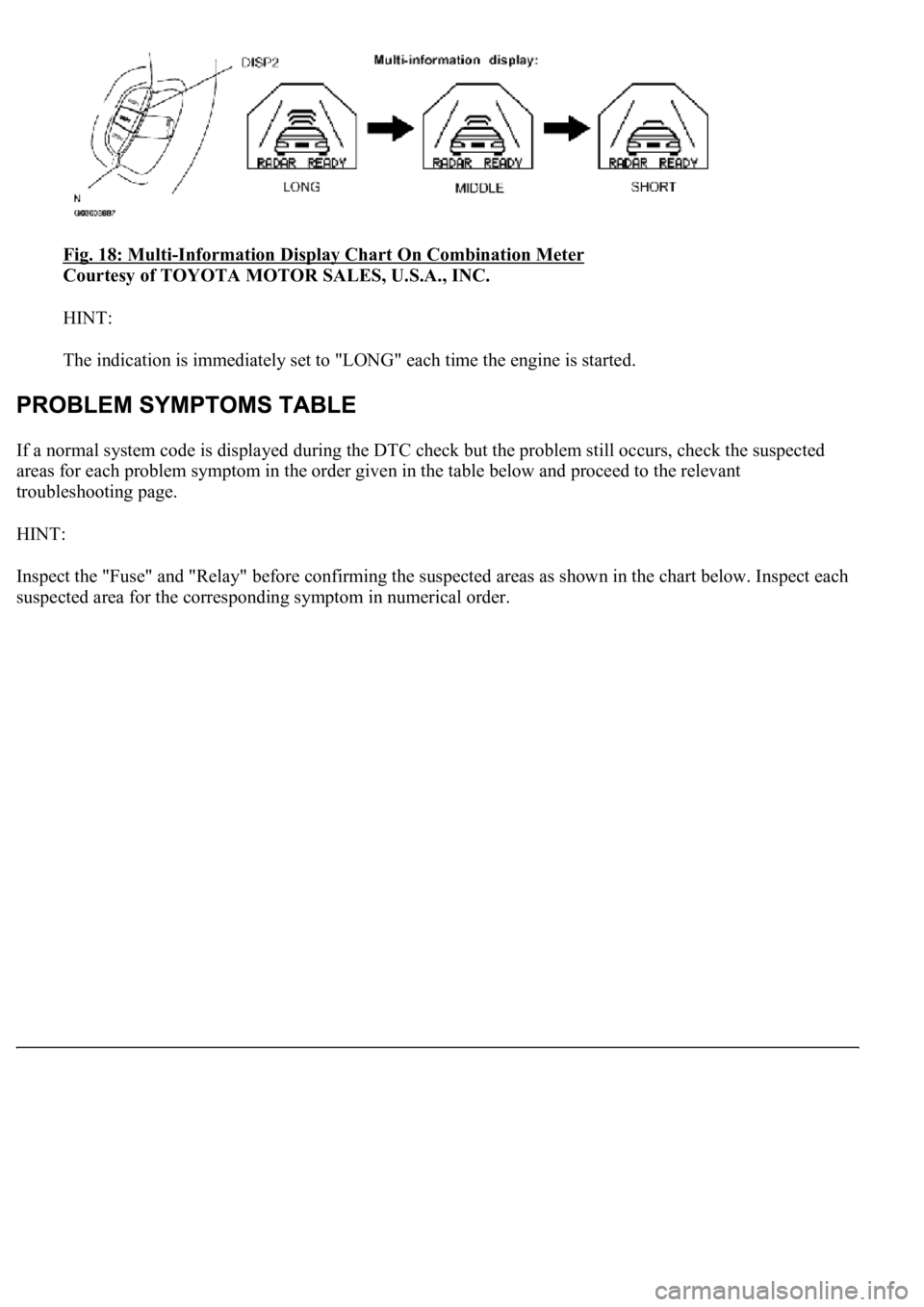
Fig. 18: Multi-Information Display Chart On Combination Meter
Courtesy of TOYOTA MOTOR SALES, U.S.A., INC.
HINT:
The indication is immediately set to "LONG" each time the engine is started.
If a normal system code is displayed during the DTC check but the problem still occurs, check the suspected
areas for each problem symptom in the order given in the table below and proceed to the relevant
troubleshooting page.
HINT:
Inspect the "Fuse" and "Relay" before confirming the suspected areas as shown in the chart below. Inspect each
suspected area for the correspondin
g symptom in numerical order.
Page 2485 of 4500
NG: REPLACE CRUISE CONTROL ECU ASSY (SEE REPLACEMENT )
OK: SYSTEM OK
CIRCUIT DESCRIPTION
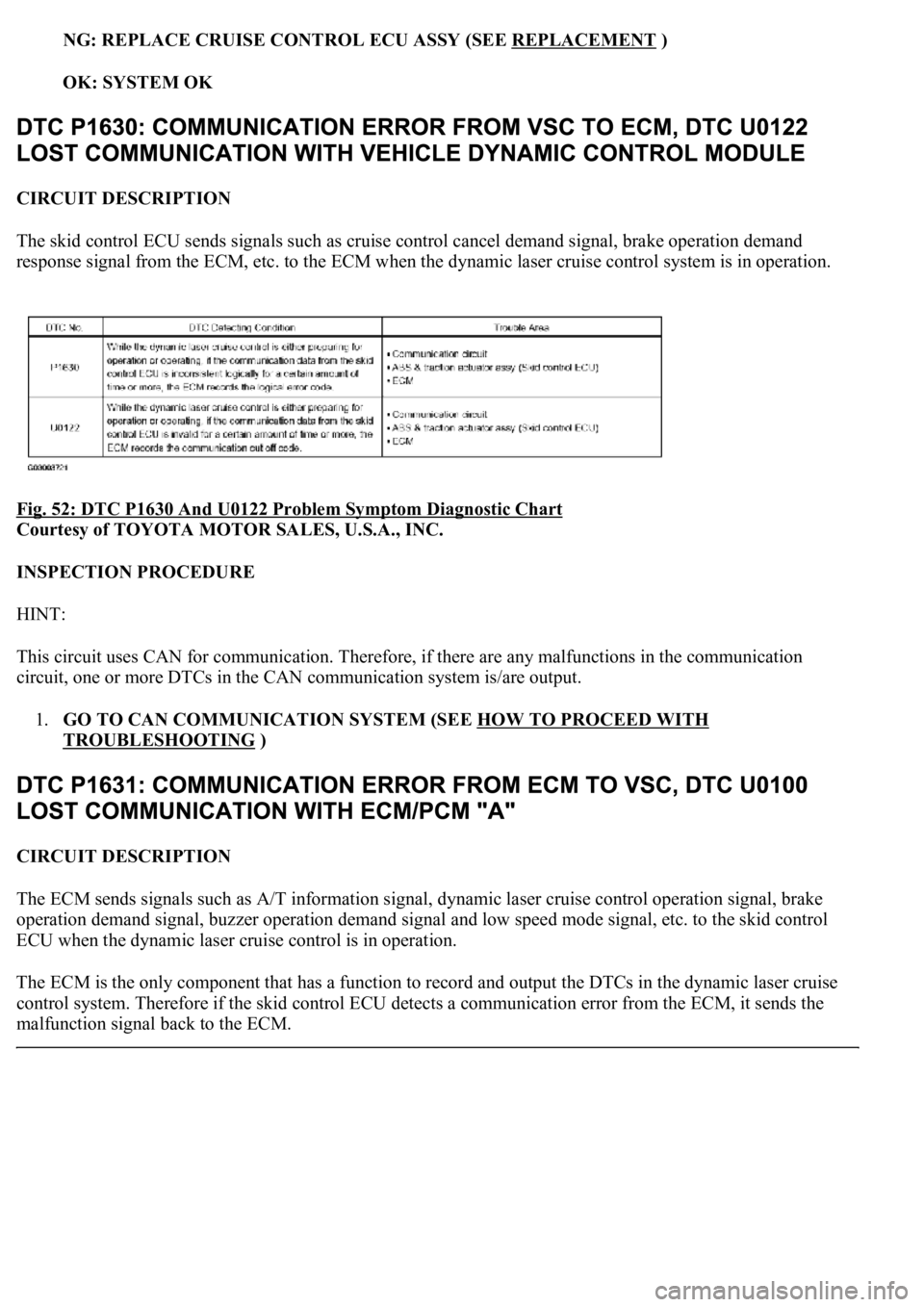
The skid control ECU sends signals such as cruise control cancel demand signal, brake operation demand
response signal from the ECM, etc. to the ECM when the dynamic laser cruise control system is in operation.
Fig. 52: DTC P1630 And U0122 Problem Symptom Diagnostic Chart
Courtesy of TOYOTA MOTOR SALES, U.S.A., INC.
INSPECTION PROCEDURE
HINT:
This circuit uses CAN for communication. Therefore, if there are any malfunctions in the communication
circuit, one or more DTCs in the CAN communication system is/are output.
1.GO TO CAN COMMUNICATION SYSTEM (SEE HOW TO PROCEED WITH
TROUBLESHOOTING )
CIRCUIT DESCRIPTION
The ECM sends signals such as A/T information signal, dynamic laser cruise control operation signal, brake
operation demand signal, buzzer operation demand signal and low speed mode signal, etc. to the skid control
ECU when the dynamic laser cruise control is in operation.
<0037004b004800030028002600300003004c005600030057004b0048000300520051004f005c000300460052005000530052005100480051005700030057004b004400570003004b0044005600030044000300490058005100460057004c00520051000300
57005200030055004800460052005500470003004400510047[ output the DTCs in the dynamic laser cruise
control system. Therefore if the skid control ECU detects a communication error from the ECM, it sends the
malfunction signal back to the ECM.
Page 2550 of 4500
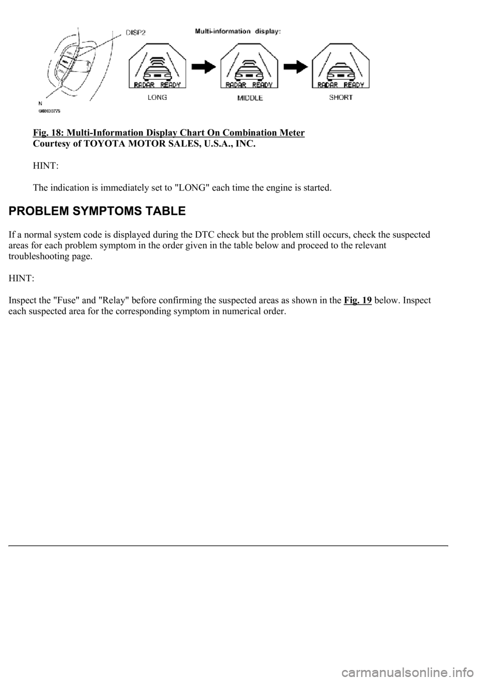
Fig. 18: Multi-Information Display Chart On Combination Meter
Courtesy of TOYOTA MOTOR SALES, U.S.A., INC.
HINT:
The indication is immediately set to "LONG" each time the engine is started.
If a normal system code is displayed during the DTC check but the problem still occurs, check the suspected
areas for each problem symptom in the order given in the table below and proceed to the relevant
troubleshooting page.
HINT:
Inspect the "Fuse" and "Relay" before confirming the suspected areas as shown in the Fig. 19
below. Inspect
each suspected area for the correspondin
g symptom in numerical order.
Page 2586 of 4500
4. Clear the DTC and then recheck for DTCs.
OK: DTC is not output.
HINT:
If DTC P1617 is still output after performing the above procedures, replace the distance control
ECU.
If the DTC P1617 is still output after replacing the distance control ECU, replace the ECM.
NG: REPLACE CRUISE CONTROL ECU ASSY (SEE REPLACEMENT
)
OK: SYSTEM OK
CIRCUIT DESCRIPTION
The skid control ECU sends signals such as cruise control cancel demand signal, brake operation demand
response signal from the ECM, etc. to the ECM when the dynamic radar cruise control system is in operation.
Fig. 55: DTC P1630 And U0122 Problem Symptom Diagnostic Chart
Courtesy of TOYOTA MOTOR SALES, U.S.A., INC.
INSPECTION PROCEDURE
HINT:
This circuit uses CAN for communication. Therefore, if there are any malfunctions in the communication
circuit, one or more DTCs in the CAN communication system is/are output.
1.GO TO CAN COMMUNICATION SYSTEM (SEE PRECAUTION
)
Page 2686 of 4500
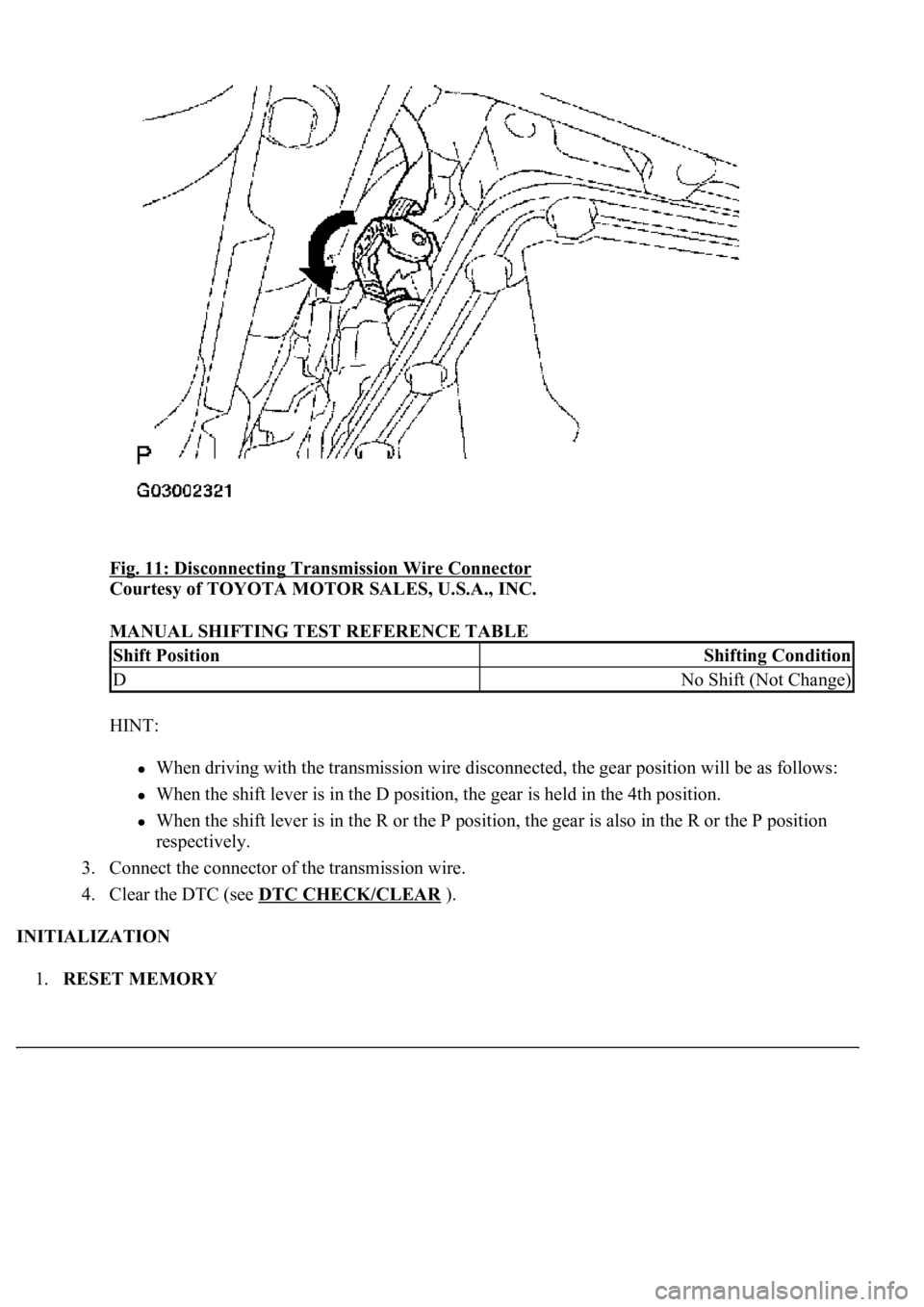
Fig. 11: Disconnecting Transmission Wire Connector
Courtesy of TOYOTA MOTOR SALES, U.S.A., INC.
MANUAL SHIFTING TEST REFERENCE TABLE
HINT:
When driving with the transmission wire disconnected, the gear position will be as follows:
When the shift lever is in the D position, the gear is held in the 4th position.
When the shift lever is in the R or the P position, the gear is also in the R or the P position
respectively.
3. Connect the connector of the transmission wire.
4. Clear the DTC (see DTC CHECK/CLEAR
).
INITIALIZATION
1.RESET MEMORY
Shift PositionShifting Condition
DNo Shift (Not Change)
Page 2715 of 4500
CHECK BATTERY VOLTAGE
Battery voltage: 11 to 14 V
If voltage is below 11 V, replace the battery before proceeding.
CHECK MIL
a. Check that the MIL illuminates when turning the ignition switch ON.
If the MIL does not illuminate, there is a problem in the MIL circuit (refer to MIL CIRCUIT
)
b. When the engine is started, the MIL should turn off.
ALL READINESS
For this vehicle, using the hand-held tester allows readiness codes corresponding to all DTCs to be read. When
diagnosis (normal or malfunctioning) has been complete, readiness codes are set. Enter the following menus:
ENHANCED OBD II/ MONITOR STATUS on the hand-held tester.
DTC CHECK/CLEAR
1.CHECK DTC
DTCs which are stored in the ECM can be displayed with the hand-held tester or generic OBD II scan-
tool.
These scan tools can display pending DTCs and current DTCs. Some DTC aren't stored if the ECM
doesn't detect a malfunction during consecutive driving. However, the detected malfunction during once
driving is stored as pending DTC.
1. Connect the hand-held tester to the Controller Area Network Vehicle Interface Module (CAN
VIM). Then connect the CAN VIM to the Data Link Connector 3 (DLC3).
2. Turn the ignition switch ON.
3. Enter the following menus: DIAGNOSIS/ ENHANCED OBD II/ DTC INFO/ CURRENT CODES
(or PENDING CODE).
4. Confirm the DTCs and freeze frame data and then write them down.
5. See DIAGNOSTIC TROUBLE CODE CHART
to confirm the details of the DTCs.
CAN bus linehigher
Page 2894 of 4500
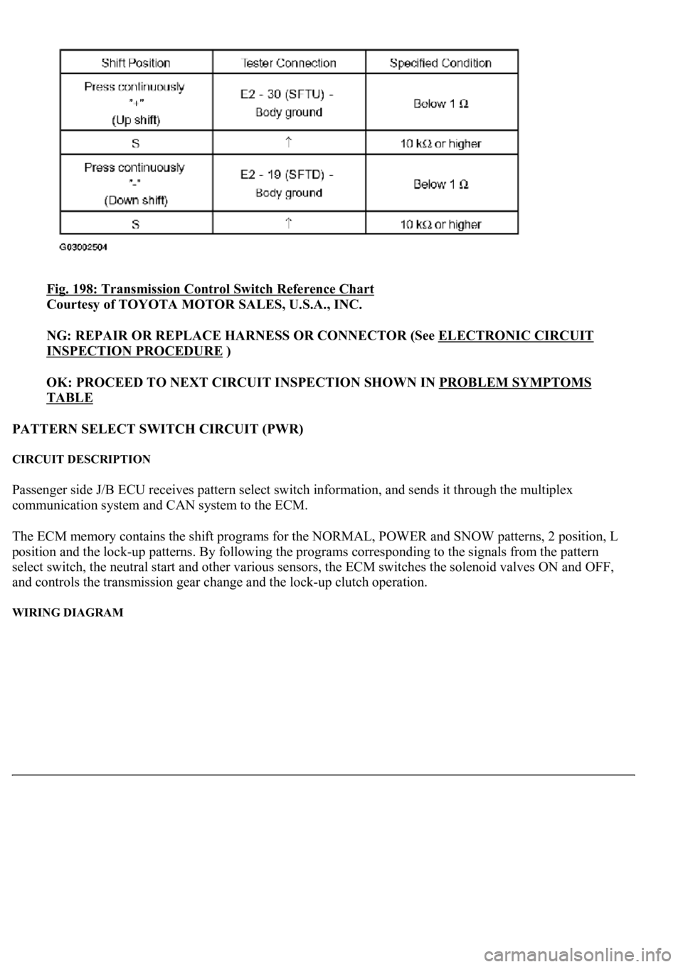
Fig. 198: Transmission Control Switch Reference Chart
Courtesy of TOYOTA MOTOR SALES, U.S.A., INC.
NG: REPAIR OR REPLACE HARNESS OR CONNECTOR (See ELECTRONIC CIRCUIT
INSPECTION PROCEDURE )
OK: PROCEED TO NEXT CIRCUIT INSPECTION SHOWN IN PROBLEM SYMPTOMS
TABLE
PATTERN SELECT SWITCH CIRCUIT (PWR)
CIRCUIT DESCRIPTION
Passenger side J/B ECU receives pattern select switch information, and sends it through the multiplex
communication system and CAN system to the ECM.
The ECM memory contains the shift programs for the NORMAL, POWER and SNOW patterns, 2 position, L
position and the loc
k-up patterns. By following the programs corresponding to the signals from the pattern
select switch, the neutral start and other various sensors, the ECM switches the solenoid valves ON and OFF,
and controls the transmission gear change and the lock-up clutch operation.
WIRING DIAGRAM
Page 2900 of 4500
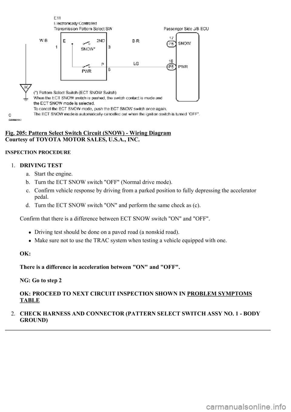
Fig. 205: Pattern Select Switch Circuit (SNOW) - Wiring Diagram
Courtesy of TOYOTA MOTOR SALES, U.S.A., INC.
INSPECTION PROCEDURE
1.DRIVING TEST
a. Start the engine.
b. Turn the ECT SNOW switch "OFF" (Normal drive mode).
c. Confirm vehicle response by driving from a parked position to fully depressing the accelerator
pedal.
d. Turn the ECT SNOW switch "ON" and perform the same check as (c).
Confirm that there is a difference between ECT SNOW switch "ON" and "OFF".
Driving test should be done on a paved road (a nonskid road).
Make sure not to use the TRAC system when testing a vehicle equipped with one.
OK:
There is a difference in acceleration between "ON" and "OFF".
NG: Go to step 2
OK: PROCEED TO NEXT CIRCUIT INSPECTION SHOWN IN PROBLEM SYMPTOMS
TABLE
2.CHECK HARNESS AND CONNECTOR (PATTERN SELECT SWITCH ASSY NO. 1 - BODY
GROUND)
Page 3198 of 4500
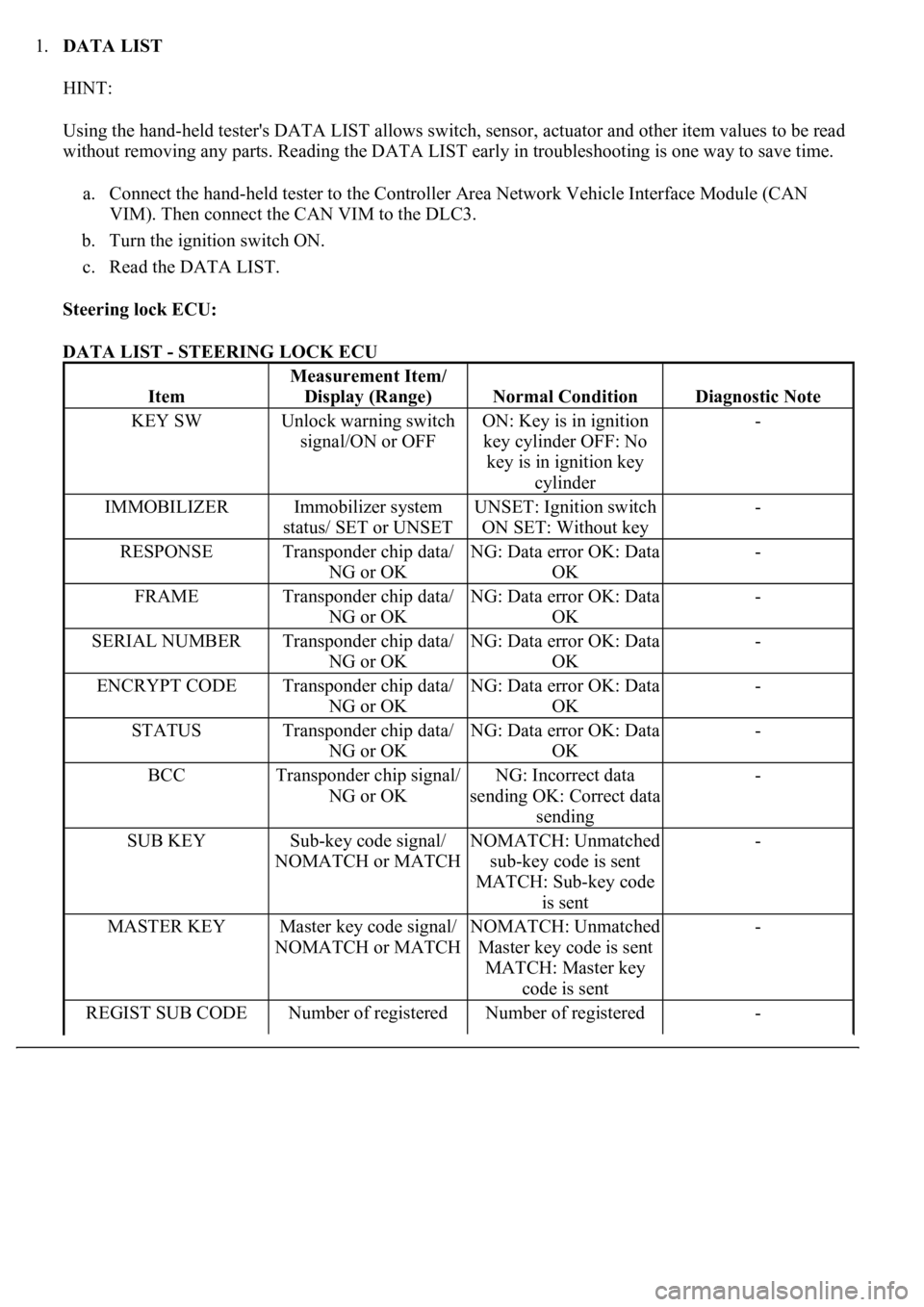
1.DATA LIST
HINT:
Using the hand-held tester's DATA LIST allows switch, sensor, actuator and other item values to be read
without removing any parts. Reading the DATA LIST early in troubleshooting is one way to save time.
a. Connect the hand-held tester to the Controller Area Network Vehicle Interface Module (CAN
VIM). Then connect the CAN VIM to the DLC3.
b. Turn the ignition switch ON.
c. Read the DATA LIST.
Steering lock ECU:
DATA LIST - STEERING LOCK ECU
Item
Measurement Item/
Display (Range)
Normal ConditionDiagnostic Note
KEY SWUnlock warning switch
signal/ON or OFFON: Key is in ignition
key cylinder OFF: No
key is in ignition key
cylinder-
IMMOBILIZERImmobilizer system
status/ SET or UNSETUNSET: Ignition switch
ON SET: Without key-
RESPONSETransponder chip data/
NG or OKNG: Data error OK: Data
OK-
FRAMETransponder chip data/
NG or OKNG: Data error OK: Data
OK-
SERIAL NUMBERTransponder chip data/
NG or OKNG: Data error OK: Data
OK-
ENCRYPT CODETransponder chip data/
NG or OKNG: Data error OK: Data
OK-
STATUSTransponder chip data/
NG or OKNG: Data error OK: Data
OK-
BCCTransponder chip signal/
NG or OKNG: Incorrect data
sending OK: Correct data
sending-
SUB KEYSub-key code signal/
NOMATCH or MATCHNOMATCH: Unmatched
sub-key code is sent
MATCH: Sub-key code
is sent-
MASTER KEYMaster key code signal/
NOMATCH or MATCHNOMATCH: Unmatched
Master key code is sent
MATCH: Master key
code is sent-
REGIST SUB CODENumber of registered Number of registered -