Rear LEXUS LS430 2003 Factory Owner's Guide
[x] Cancel search | Manufacturer: LEXUS, Model Year: 2003, Model line: LS430, Model: LEXUS LS430 2003Pages: 4500, PDF Size: 87.45 MB
Page 239 of 4500
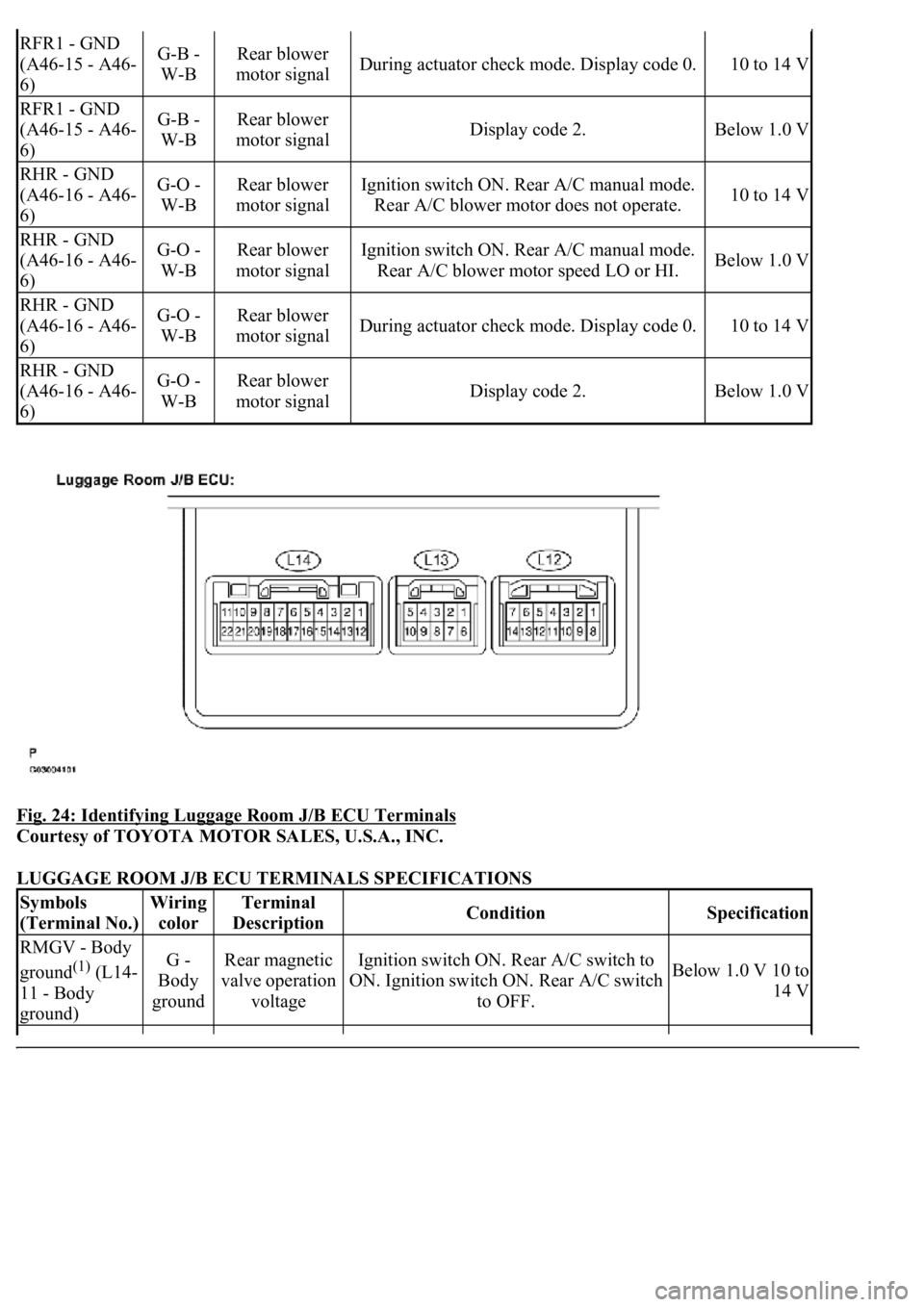
Fig. 24: Identifying Luggage Room J/B ECU Terminals
Courtesy of TOYOTA MOTOR SALES, U.S.A., INC.
LUGGAGE ROOM J/B ECU TERMINALS SPECIFICATIONS
RFR1 - GND
(A46-15 - A46-
6)G-B -
W-BRear blower
motor signalDuring actuator check mode. Display code 0.10 to 14 V
RFR1 - GND
(A46-15 - A46-
6)G-B -
W-BRear blower
motor signalDisplay code 2.Below 1.0 V
RHR - GND
(A46-16 - A46-
6)G-O -
W-BRear blower
motor signalIgnition switch ON. Rear A/C manual mode.
Rear A/C blower motor does not operate.10 to 14 V
RHR - GND
(A46-16 - A46-
6)G-O -
W-BRear blower
motor signalIgnition switch ON. Rear A/C manual mode.
Rear A/C blower motor speed LO or HI.Below 1.0 V
RHR - GND
(A46-16 - A46-
6)G-O -
W-BRear blower
motor signalDuring actuator check mode. Display code 0.10 to 14 V
RHR - GND
(A46-16 - A46-
6)G-O -
W-BRear blower
motor signalDisplay code 2.Below 1.0 V
Symbols
(Terminal No.)Wiring
colorTerminal
DescriptionConditionSpecification
RMGV - Body
ground
(1) (L14-
11 - Body
ground)G -
Body
groundRear magnetic
valve operation
voltageIgnition switch ON. Rear A/C switch to
ON. Ignition switch ON. Rear A/C switch
to OFF.Below 1.0 V 10 to
14 V
Page 240 of 4500

HINT:
The followings are the possible items to be customized.
AIR CONDITIONER
AIR CONDITIONER CUSTOMIZE PARAMETERS
SMOK - Body
ground (L14-16
- Body ground)L - Body
groundSmoke sensor
operation signal
Ignition switch ON. Rear A/C switch to
AUTO. By using cigarette smoke. Ignition
switch ON. Rear A/C switch to AUTO. By
not using cigarette smoke.
Above 4.0 V
Below 1.0 V
AUTO - Body
ground (L14-17
- Body ground)W -
Body
groundAuto switch
signal
Ignition switch ON. Rear A/C rear seat
AUTO indicator lights up. Ignition switch
ON. Rear A/C rear seat AUTO indicator
does not light up.
Below 1.0 V 10 to
14 V
RHR - Body
ground (L14-18
- Body ground)V -
Body
groundRear blower
motor operation
signal
Ignition switch ON. Rear A/C manual
mode. Rear A/C blower motor does not
operate. Ignition switch ON. Rear A/C
manual mode. Rear A/C blower motor
speed LO or HI. During actuator check
mode. Display code 0. Display code 2.
10 to 14 V Below
1.0 V 10 to 14 V
Below 1.0 V
RFR - Body
ground (L14-19
- Body ground)Y -
Body
groundRear blower
motor operation
signal
Ignition switch ON. Rear A/C blower
motor speed to except HI. Ignition switch
ON. Rear A/C blower motor speed to HI.
During actuator check mode. Display code
0. Display code 2.
10 to 14 V Below
1.0 V 10 to 14 V
Below 1.0 V
FRS - Body
ground (L14-20
- Body ground)B -
Body
groundExhaust damper
servomotor
operation signal
Ignition switch ON. Front A/C blower
motor operates. Push "FRS" switch.
Ambient temperature below -1 °C Ignition
switch ON. Front A/C blower motor
operates. Push "REC" switch.
10 to 14 V Below
1.0 V
(1)w/ Rear A/C
DISPLAY (ITEM)DEFAULTCONTENTSSETTING
Page 244 of 4500
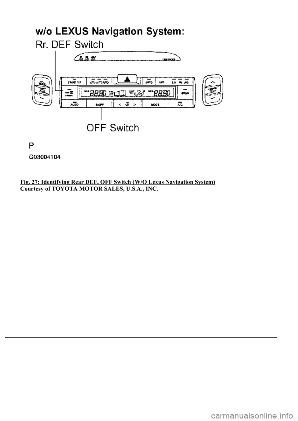
Fig. 27: Identifying Rear DEF, OFF Switch (W/O Lexus Navigation System)
Courtesy of TOYOTA MOTOR SALES, U.S.A., INC.
Page 245 of 4500
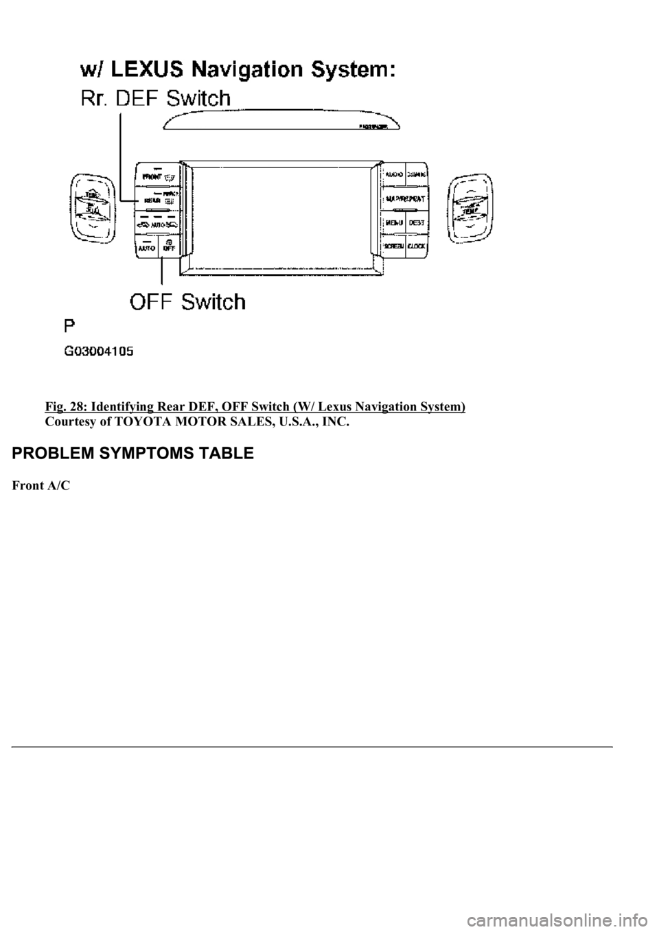
Fig. 28: Identifying Rear DEF, OFF Switch (W/ Lexus Navigation System)
Courtesy of TOYOTA MOTOR SALES, U.S.A., INC.
Front A/C
Page 247 of 4500
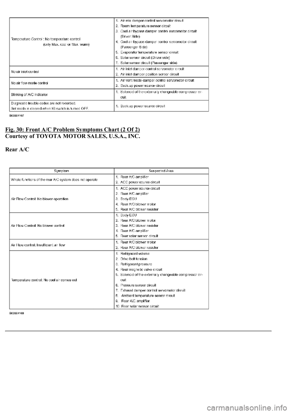
Fig. 30: Front A/C Problem Symptoms Chart (2 Of 2)
Courtesy of TOYOTA MOTOR SALES, U.S.A., INC.
Rear A/C
Page 248 of 4500

Fig. 31: Rear A/C Problem Symptoms Chart
Courtesy of TOYOTA MOTOR SALES, U.S.A., INC.
Air Purifier
Fig. 32: Air Purifier Problem Symptoms Chart
Courtesy of TOYOTA MOTOR SALES, U.S.A., INC.
Intelligent Swing Register
Fig. 33: Intelligent Swing Register Problem Symptoms Chart
Courtesy of TOYOTA MOTOR SALES, U.S.A., INC.
If a malfunction code is displayed during the DTC check (sensor check), check the circuit listed for that code in
the table below.
DIAGNOSTIC TROUBLE CODE CHART
DTCDescription
DTC B1411ROOM TEMPERATURE SENSOR CIRCUIT
DTC B1412AMBIENT TEMPERATURE SENSOR CIRCUIT
DTC B1413EVAPORATOR TEMPERATURE SENSOR CIRCUIT
DTC B1415AIR DUCT SENSOR CIRCUIT (DRIVER SIDE)
DTC B1416AIR DUCT SENSOR CIRCUIT (PASSENGER SIDE)
DTC B1418EMISSION GAS SENSOR CIRCUIT
DTC B1421SOLAR SENSOR CIRCUIT (PASSENGER SIDE)
DTC B1423PRESSURE SWITCH CIRCUIT
DTC B1424SOLAR SENSOR CIRCUIT (DRIVER SIDE)
DTC B1428REAR SOLAR SENSOR CIRCUIT
DTC B1432AIR INLET DAMPER POSITION SENSOR CIRCUIT
DTC B1434MAX COOL DAMPER POSITION SENSOR CIRCUIT (DRIVER SIDE)
DTC B1435MAX COOL DAMPER POSITION SENSOR CIRCUIT (PASSENGER SIDE)
Page 299 of 4500
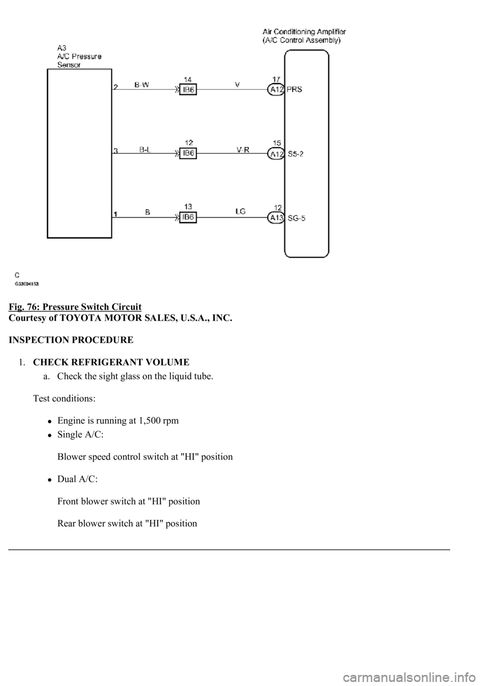
Fig. 76: Pressure Switch Circuit
Courtesy of TOYOTA MOTOR SALES, U.S.A., INC.
INSPECTION PROCEDURE
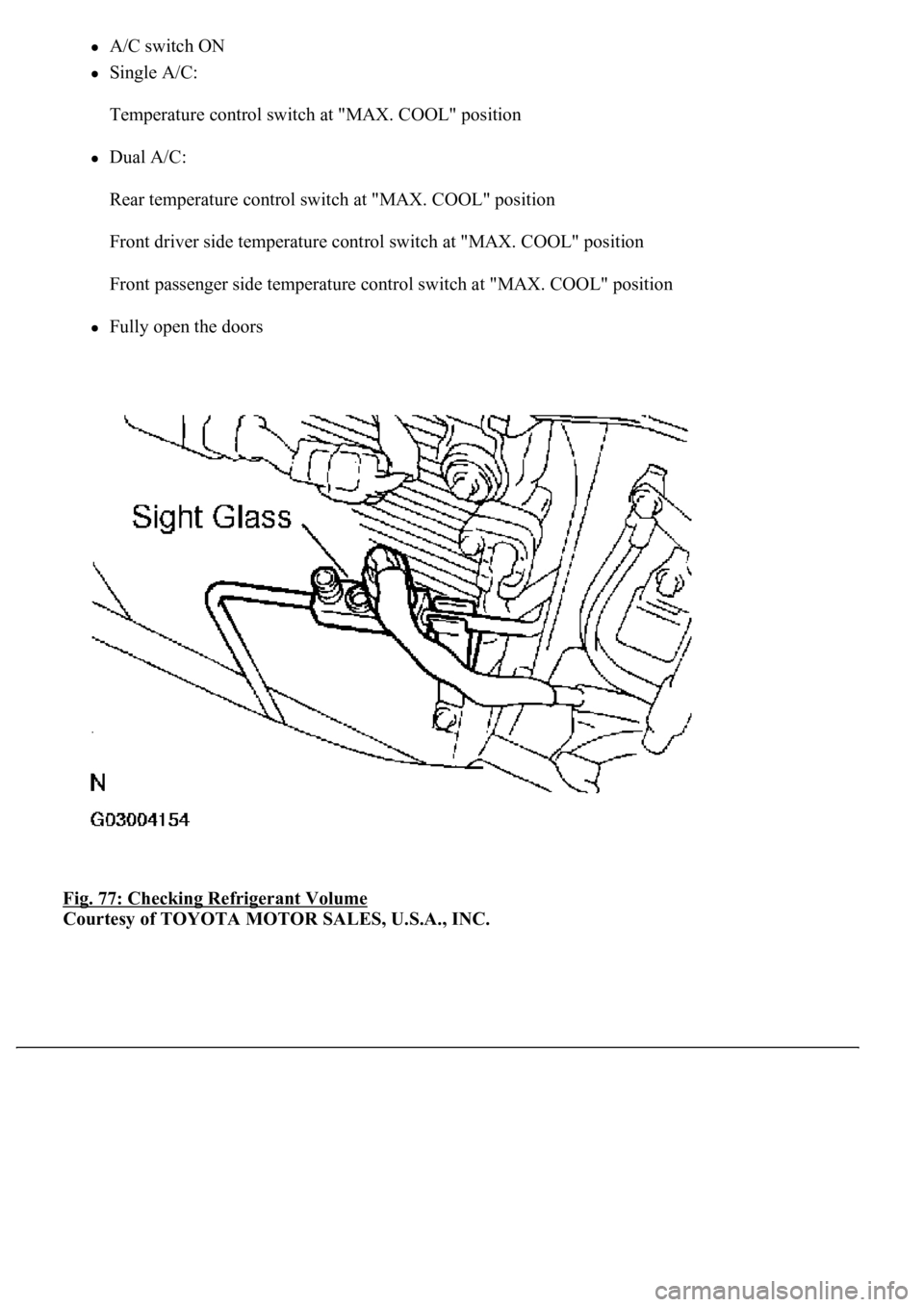
1.CHECK REFRIGERANT VOLUME
a. Check the sight glass on the liquid tube.
Test conditions:
Engine is running at 1,500 rpm
Single A/C:
Blower speed control switch at "HI" position
Dual A/C:
Front blower switch at "HI" position
Rear blower switch at "HI" position
Page 300 of 4500
A/C switch ON
Single A/C:
Temperature control switch at "MAX. COOL" position
Dual A/C:
Rear temperature control switch at "MAX. COOL" position
Front driver side temperature control switch at "MAX. COOL" position
Front passenger side temperature control switch at "MAX. COOL" position
Fully open the doors
Fig. 77: Checking Refrigerant Volume
Courtesy of TOYOTA MOTOR SALES, U.S.A., INC.
Page 315 of 4500
Courtesy of TOYOTA MOTOR SALES, U.S.A., INC.
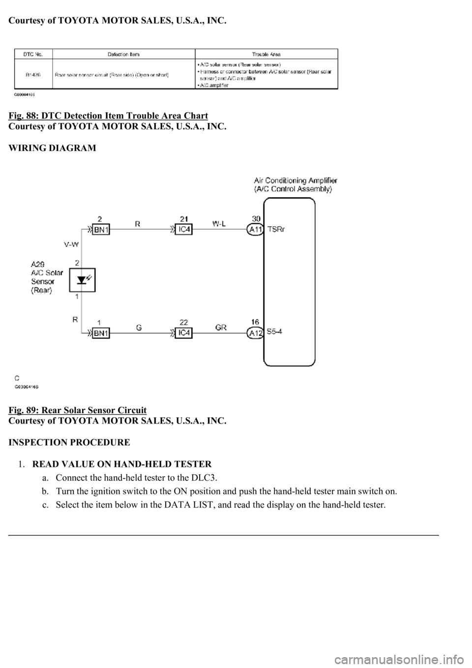
Fig. 88: DTC Detection Item Trouble Area Chart
Courtesy of TOYOTA MOTOR SALES, U.S.A., INC.
WIRING DIAGRAM
Fig. 89: Rear Solar Sensor Circuit
Courtesy of TOYOTA MOTOR SALES, U.S.A., INC.
INSPECTION PROCEDURE
1.READ VALUE ON HAND-HELD TESTER
a. Connect the hand-held tester to the DLC3.
b. Turn the ignition switch to the ON position and push the hand-held tester main switch on.
c. Select the item below in the DATA LIST, and read the displa
y on the hand-held tester.
Page 316 of 4500
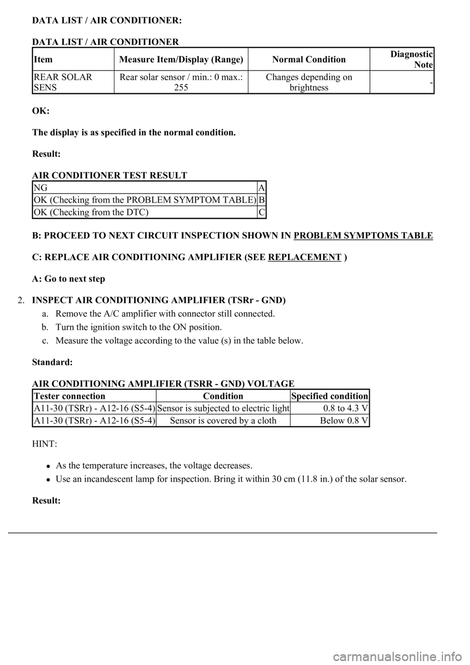
DATA LIST / AIR CONDITIONER:
DATA LIST / AIR CONDITIONER
OK:
The display is as specified in the normal condition.
Result:
AIR CONDITIONER TEST RESULT
B: PROCEED TO NEXT CIRCUIT INSPECTION SHOWN IN PROBLEM SYMPTOMS TABLE
C: REPLACE AIR CONDITIONING AMPLIFIER (SEE REPLACEMENT )
A: Go to next step
2.INSPECT AIR CONDITIONING AMPLIFIER (TSRr - GND)
a. Remove the A/C amplifier with connector still connected.
b. Turn the ignition switch to the ON position.
c. Measure the voltage according to the value (s) in the table below.
Standard:
AIR CONDITIONING AMPLIFIER (TSRR - GND) VOLTAGE
HINT:
As the temperature increases, the voltage decreases.
Use an incandescent lamp for inspection. Bring it within 30 cm (11.8 in.) of the solar sensor.
Result:
ItemMeasure Item/Display (Range)Normal ConditionDiagnostic
Note
REAR SOLAR
SENSRear solar sensor / min.: 0 max.:
255Changes depending on
brightness-
NGA
OK (Checking from the PROBLEM SYMPTOM TABLE)B
OK (Checking from the DTC)C
Tester connectionConditionSpecified condition
A11-30 (TSRr) - A12-16 (S5-4)Sensor is subjected to electric light0.8 to 4.3 V
A11-30 (TSRr) - A12-16 (S5-4)Sensor is covered by a clothBelow 0.8 V