oil pressure LEXUS LS430 2003 Factory Repair Manual
[x] Cancel search | Manufacturer: LEXUS, Model Year: 2003, Model line: LS430, Model: LEXUS LS430 2003Pages: 4500, PDF Size: 87.45 MB
Page 1 of 4500
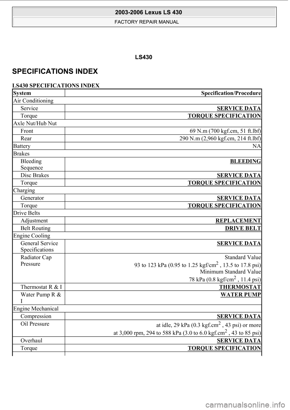
LS430 SPECIFICATIONS INDEX
SystemSpecification/Procedure
Air Conditioning
ServiceSERVICE DATA
TorqueTORQUE SPECIFICATION
Axle Nut/Hub Nut
Front69 N.m (700 kgf.cm, 51 ft.lbf)
Rear290 N.m (2,960 kgf.cm, 214 ft.lbf)
BatteryNA
Brakes
Bleeding
SequenceBLEEDING
Disc BrakesSERVICE DATA
TorqueTORQUE SPECIFICATION
Charging
GeneratorSERVICE DATA
TorqueTORQUE SPECIFICATION
Drive Belts
AdjustmentREPLACEMENT
Belt RoutingDRIVE BELT
Engine Cooling
General Service
SpecificationsSERVICE DATA
Radiator Cap
PressureStandard Value
93 to 123 kPa (0.95 to 1.25 kgf/cm
2 , 13.5 to 17.8 psi)
Minimum Standard Value
78 kPa (0.8 kgf/cm
2 , 11.4 psi)
Thermostat R & ITHERMOSTAT
Water Pump R &
IWATER PUMP
Engine Mechanical
CompressionSERVICE DATA
Oil Pressureat idle, 29 kPa (0.3 kgf.cm2 , 43 psi) or more
at 3,000 rpm, 294 to 588 kPa (3.0 to 6.0 kgf.cm
2 , 43 to 85 psi)
OverhaulSERVICE DATA
TorqueTORQUE SPECIFICATION
Page 8 of 4500
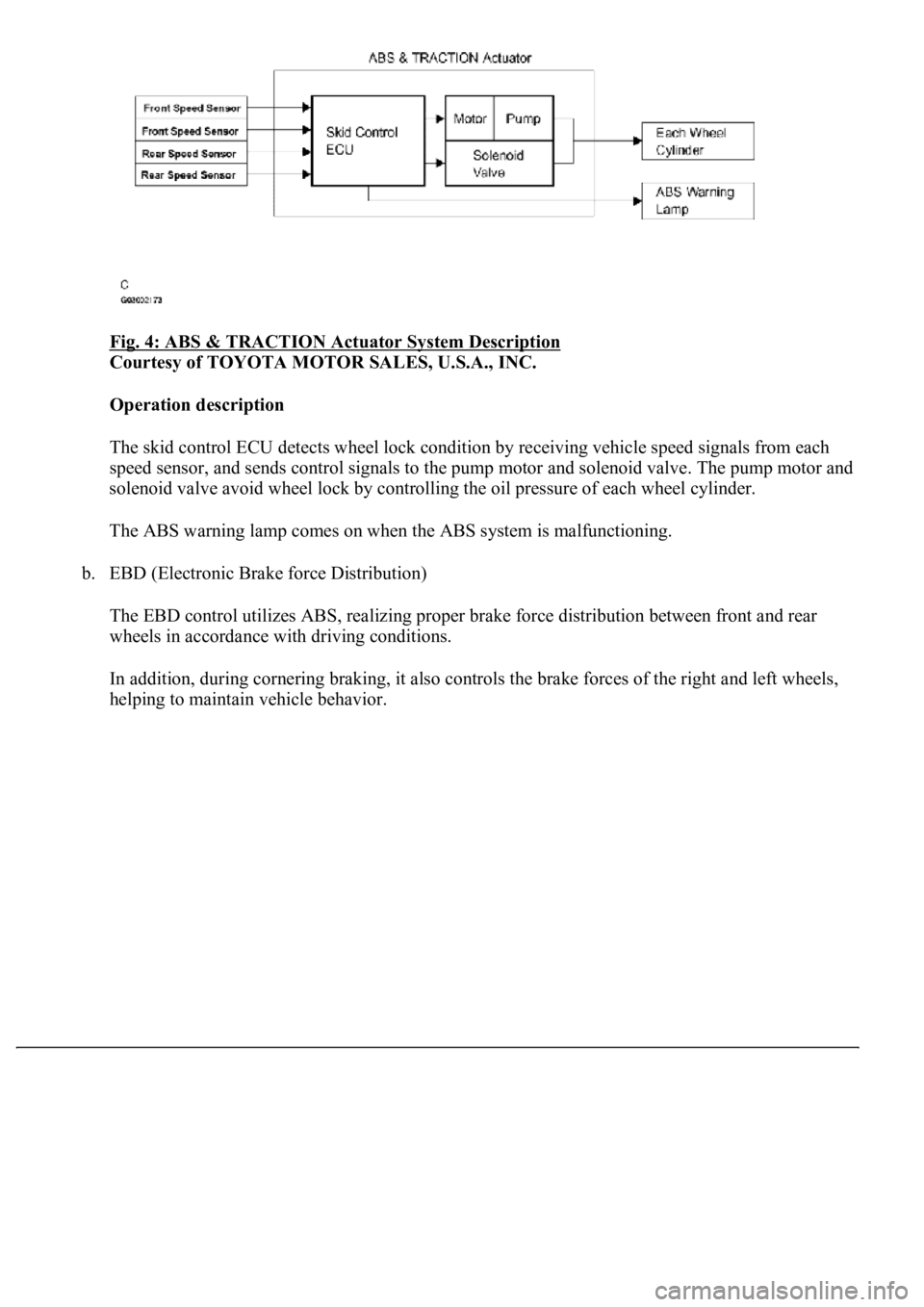
Fig. 4: ABS & TRACTION Actuator System Description
Courtesy of TOYOTA MOTOR SALES, U.S.A., INC.
Operation description
The skid control ECU detects wheel lock condition by receiving vehicle speed signals from each
<005600530048004800470003005600480051005600520055000f00030044005100470003005600480051004700560003004600520051005700550052004f00030056004c004a00510044004f005600030057005200030057004b0048000300530058005000
53000300500052005700520055000300440051004700030056[olenoid valve. The pump motor and
solenoid valve avoid wheel lock by controlling the oil pressure of each wheel cylinder.
The ABS warning lamp comes on when the ABS system is malfunctioning.
b. EBD (Electronic Brake force Distribution)
The EBD control utilizes ABS, realizing proper brake force distribution between front and rear
wheels in accordance with driving conditions.
In addition, during cornering braking, it also controls the brake forces of the right and left wheels,
helping to maintain vehicle behavior.
Page 9 of 4500
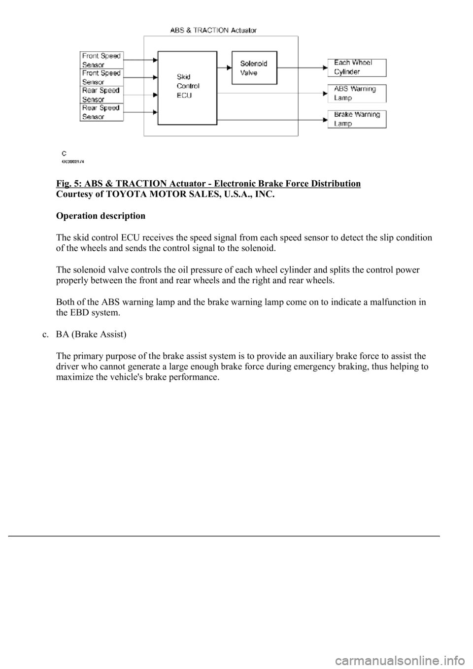
Fig. 5: ABS & TRACTION Actuator - Electronic Brake Force Distribution
Courtesy of TOYOTA MOTOR SALES, U.S.A., INC.
Operation description
The skid control ECU receives the speed signal from each speed sensor to detect the slip condition
<0052004900030057004b00480003005a004b00480048004f0056000300440051004700030056004800510047005600030057004b00480003004600520051005700550052004f00030056004c004a00510044004f00030057005200030057004b0048000300
560052004f004800510052004c004700110003[
The solenoid valve controls the oil pressure of each wheel cylinder and splits the control power
properly between the front and rear wheels and the right and rear wheels.
Both of the ABS warning lamp and the brake warning lamp come on to indicate a malfunction in
the EBD system.
c. BA (Brake Assist)
The primary purpose of the brake assist system is to provide an auxiliary brake force to assist the
driver who cannot generate a large enough brake force during emergency braking, thus helping to
maximize the vehicle's brake performance.
Page 10 of 4500
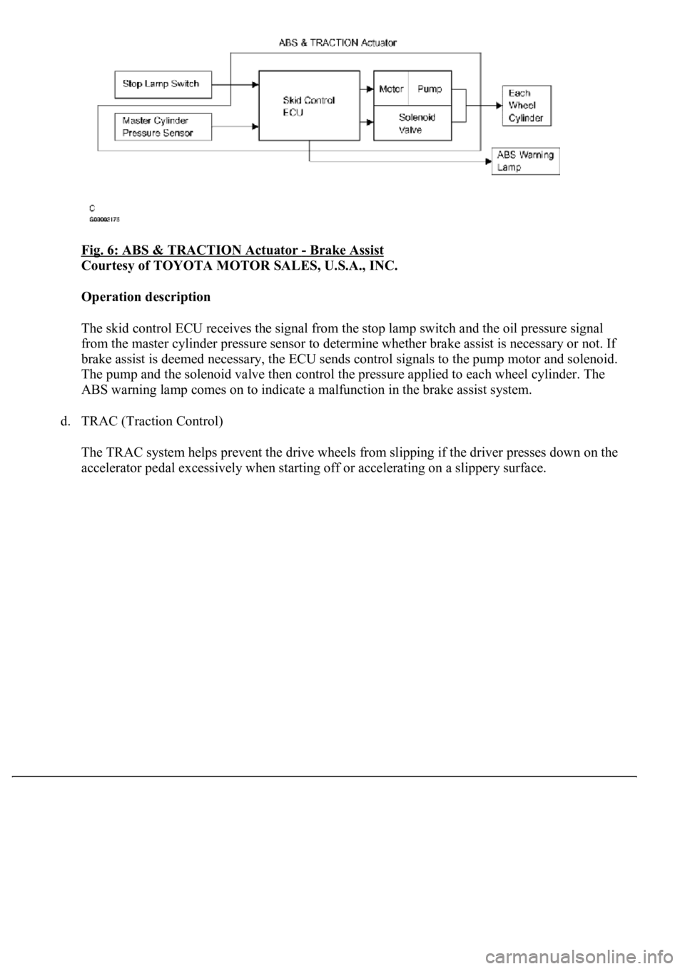
Fig. 6: ABS & TRACTION Actuator - Brake Assist
Courtesy of TOYOTA MOTOR SALES, U.S.A., INC.
Operation description
The skid control ECU receives the signal from the stop lamp switch and the oil pressure signal
from the master cylinder pressure sensor to determine whether brake assist is necessary or not. If
brake assist is deemed necessary, the ECU sends control signals to the pump motor and solenoid.
The pump and the solenoid valve then control the pressure applied to each wheel cylinder. The
ABS warning lamp comes on to indicate a malfunction in the brake assist system.
d. TRAC (Traction Control)
The TRAC system helps prevent the drive wheels from slipping if the driver presses down on the
accelerator pedal excessivel
y when starting off or accelerating on a slippery surface.
Page 11 of 4500
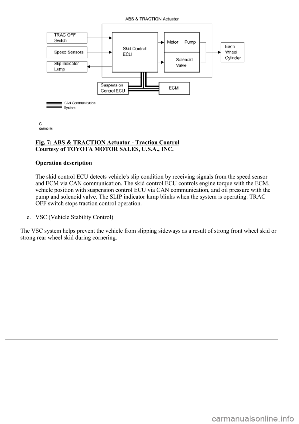
Fig. 7: ABS & TRACTION Actuator - Traction Control
Courtesy of TOYOTA MOTOR SALES, U.S.A., INC.
Operation description
The skid control ECU detects vehicle's slip condition by receiving signals from the speed sensor
<004400510047000300280026003000030059004c004400030026002400310003004600520050005000580051004c004600440057004c00520051001100030037004b004800030056004e004c00470003004600520051005700550052004f00030028002600
380003004600520051005700550052004f0056000300480051[gine torque with the ECM,
vehicle position with suspension control ECU via CAN communication, and oil pressure with the
pump and solenoid valve. The SLIP indicator lamp blinks when the system is operating. TRAC
OFF switch stops traction control operation.
e. VSC (Vehicle Stability Control)
The VSC system helps prevent the vehicle from slipping sideways as a result of strong front wheel skid or
stron
g rear wheel skid during cornering.
Page 12 of 4500
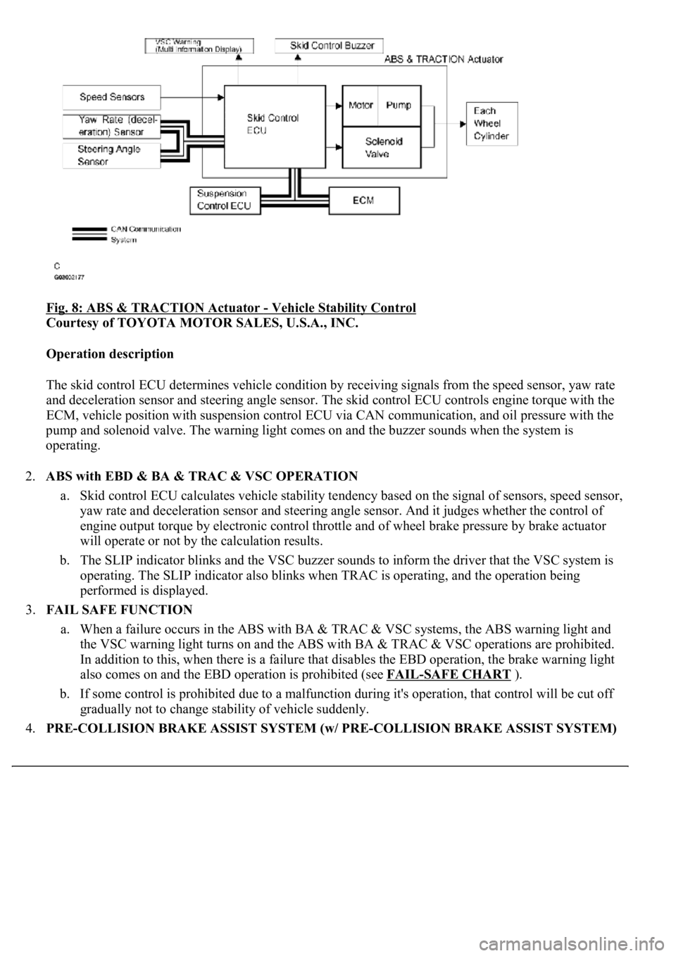
Fig. 8: ABS & TRACTION Actuator - Vehicle Stability Control
Courtesy of TOYOTA MOTOR SALES, U.S.A., INC.
Operation description
The skid control ECU determines vehicle condition by receiving signals from the speed sensor, yaw rate
and deceleration sensor and steering angle sensor. The skid control ECU controls engine torque with the
ECM, vehicle position with suspension control ECU via CAN communication, and oil pressure with the
pump and solenoid valve. The warning light comes on and the buzzer sounds when the system is
operating.
2.ABS with EBD & BA & TRAC & VSC OPERATION
a. Skid control ECU calculates vehicle stability tendency based on the signal of sensors, speed sensor,
yaw rate and deceleration sensor and steering angle sensor. And it judges whether the control of
engine output torque by electronic control throttle and of wheel brake pressure by brake actuator
will operate or not by the calculation results.
b. The SLIP indicator blinks and the VSC buzzer sounds to inform the driver that the VSC system is
operating. The SLIP indicator also blinks when TRAC is operating, and the operation being
performed is displayed.
3.FAIL SAFE FUNCTION
a. When a failure occurs in the ABS with BA & TRAC & VSC systems, the ABS warning light and
the VSC warning light turns on and the ABS with BA & TRAC & VSC operations are prohibited.
In addition to this, when there is a failure that disables the EBD operation, the brake warning light
also comes on and the EBD operation is prohibited (see FAIL
-SAFE CHART ).
b. If some control is prohibited due to a malfunction during it's operation, that control will be cut off
gradually not to change stability of vehicle suddenly.
4.PRE-COLLISION BRAKE ASSIST SYSTEM (w/ PRE-COLLISION BRAKE ASSIST SYSTEM)
Page 1847 of 4500
6.INSPECT LOW OIL PRESSURE WARNING LIGHT
a. Disconnect the connector from the low oil pressure switch.
b. Turn the ignition switch to the ON position.
c. Ground the terminal of the wire harness side connector, then check the low oil pressure warning
light.
OK:
Low oil pressure warning light comes on.
7.INSPECT BRAKE WARNING LIGHT
a. Inspect the parking brake warning light.
1. Disconnect the connector from the parking brake switch
2. Turn the ignition switch to the ON position.
3. Ground the terminal of the wire harness side connector, then check the parking brake
warning light.
OK:
Brake warning light comes on.
b. Inspect the brake fluid level warning light.
1. Disconnect the connector from the brake fluid level warning switch.
2. Turn the ignition switch to the ON position.
3. Connect a terminal to the other terminal of the wire harness side connector, then check the
brake fluid level warning switch.
OK:
Brake warning light comes on.
8.INSPECT BRAKE FLUID LEVEL WARNING SWITCH
a. Remove the reservoir tank cap and strainer.
b. Disconnect the connector.
c. Measure the resistance between the terminals.
Standard:
Float up (switch off): 10 kohms or higher
d. Use a syphon, etc. to take fluid out of the reservoir tank.
e. Measure the resistance between the terminals.
Page 1850 of 4500
psi), and check that the pressure does not drop.
If the pressure drops, check the hoses, radiator and water pump for leaks. If no external leaks are found,
check the heater core, cylinder block and head.
2.CHECK ENGINE COOLANT LEVEL AT RESERVOIR
a. Check that the engine coolant level is between the LOW and FULL lines when the engine is cold.
If the engine coolant is low, check for leaks and add "TOYOTA Super Long Life Coolant" to the
FULL line.
If "TOYOTA Super Long Life Coolant" is not available, use a similar high quality ethylene glycol
based non-silicate, non-amino, non-nitrite and non-borate coolant with long-life hybrid organic acid
technology. Do not substitute plain water for engine coolant.
3.CHECK ENGINE COOLANT QUALITY
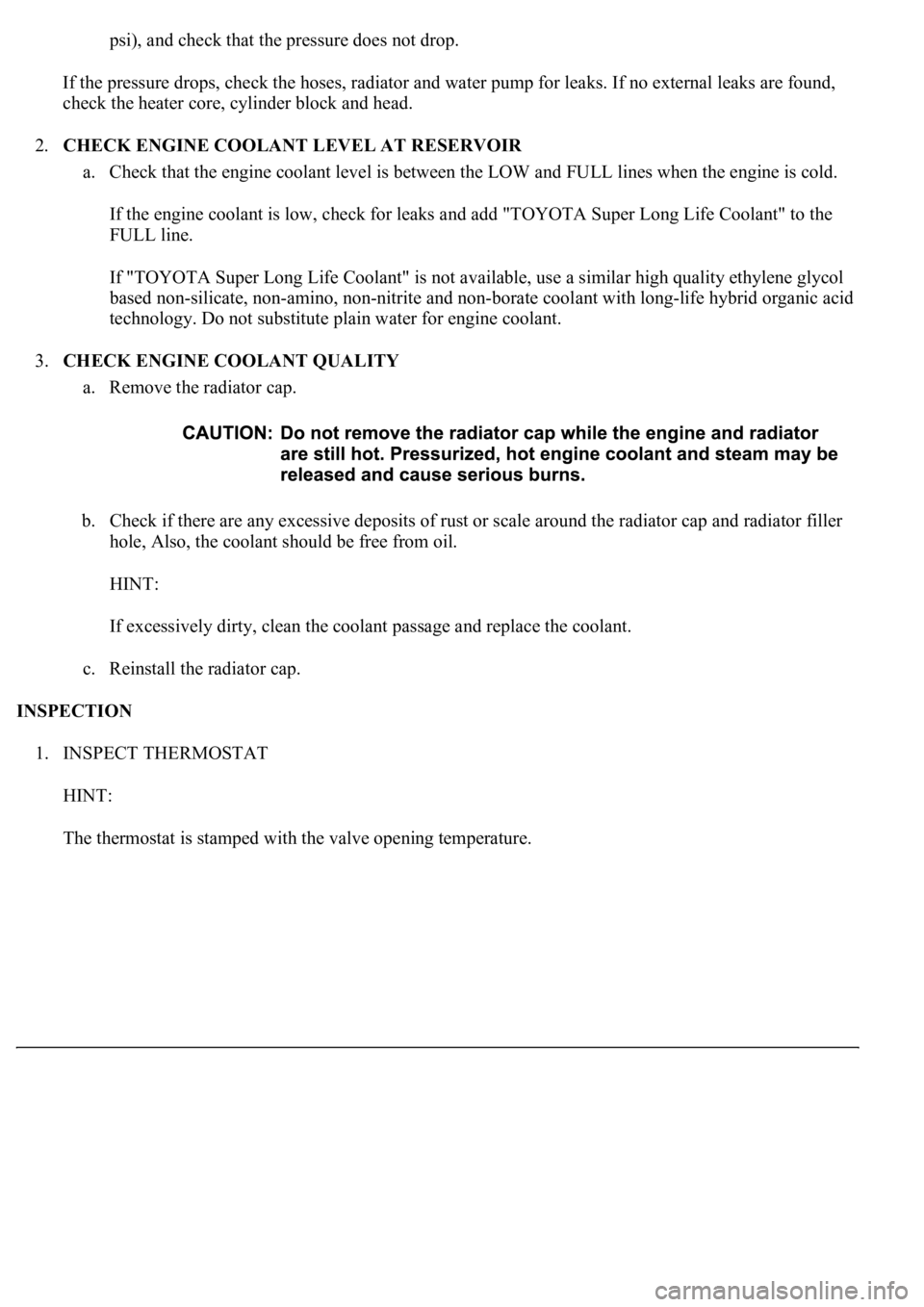
a. Remove the radiator cap.
b. Check if there are any excessive deposits of rust or scale around the radiator cap and radiator filler
hole, Also, the coolant should be free from oil.
HINT:
If excessively dirty, clean the coolant passage and replace the coolant.
c. Reinstall the radiator cap.
INSPECTION
1. INSPECT THERMOSTAT
HINT:
The thermostat is stamped with the valve openin
g temperature.
Page 1968 of 4500
a. Preparation for adjusting the radar beam axis
1. Adjust the tire pressure properly (see INSPECTION
).
2. Luggage in the vehicle, such as in the trunk, should be unloaded.
b. Adjust the standard vehicle height (vehicle with air suspension) (see INSPECTION
)
c. Adjustment in vertical direction of the millimeter wave radar sensor.
1. Remove dust and oil on the level rack of the millimeter wave radar sensor.
2. Set the specified level on the center of the level rack of the millimeter wave radar sensor.
Fig. 21: Setting Specified Level
Courtesy of TOYOTA MOTOR SALES, U.S.A., INC.
3. Using a hexagon wrench, turn and adjust screw A for vertical adjustment of the millimeter
wave radar sensor so that the air bubble is within the red frame on the level.
Standard:
Adjustable range within the red frame of the level is ± 0.2°.
Page 2634 of 4500
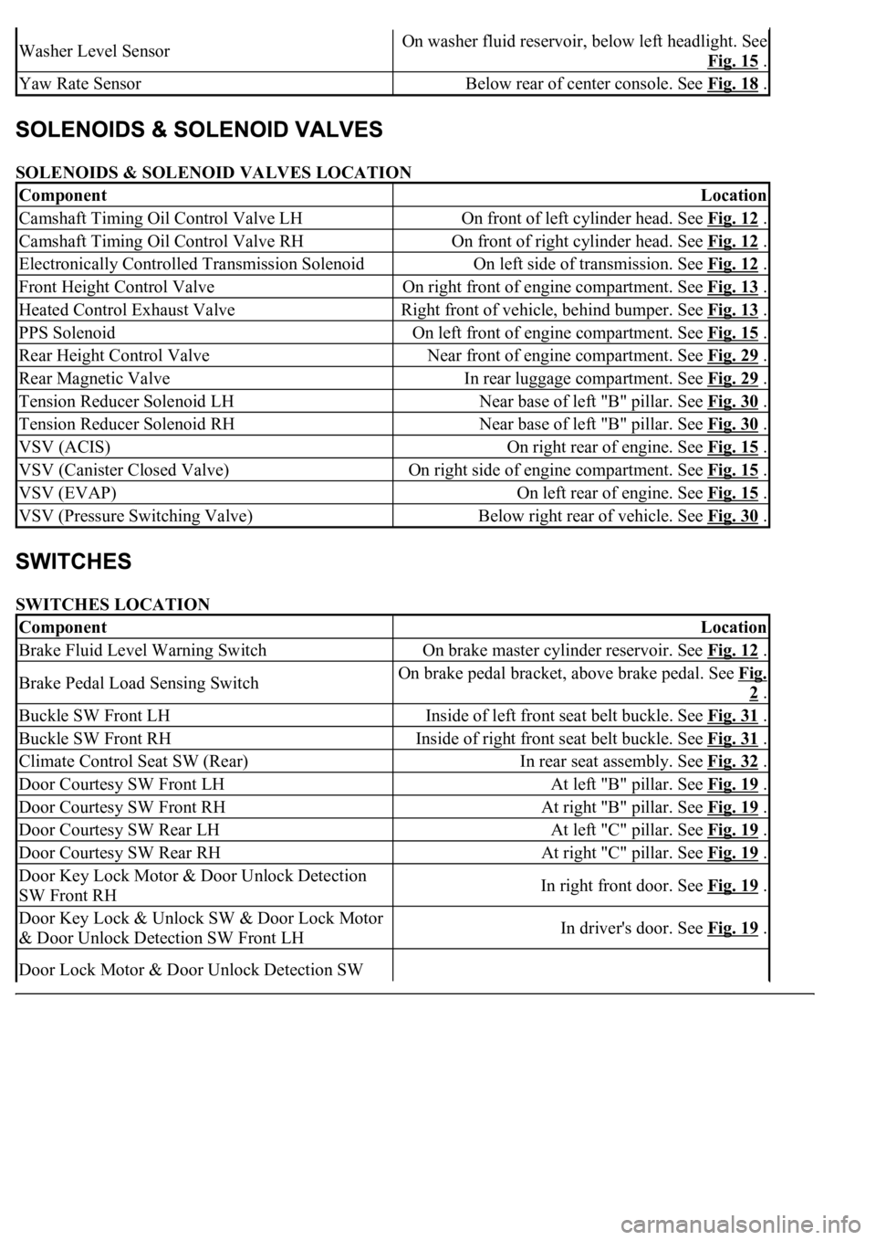
SOLENOIDS & SOLENOID VALVES LOCATION
SWITCHES LOCATION
Washer Level SensorOn washer fluid reservoir, below left headlight. See
Fig. 15
.
Yaw Rate SensorBelow rear of center console. See Fig. 18 .
ComponentLocation
Camshaft Timing Oil Control Valve LHOn front of left cylinder head. See Fig. 12 .
Camshaft Timing Oil Control Valve RHOn front of right cylinder head. See Fig. 12 .
Electronically Controlled Transmission SolenoidOn left side of transmission. See Fig. 12 .
Front Height Control ValveOn right front of engine compartment. See Fig. 13 .
Heated Control Exhaust ValveRight front of vehicle, behind bumper. See Fig. 13 .
PPS SolenoidOn left front of engine compartment. See Fig. 15 .
Rear Height Control ValveNear front of engine compartment. See Fig. 29 .
Rear Magnetic ValveIn rear luggage compartment. See Fig. 29 .
Tension Reducer Solenoid LHNear base of left "B" pillar. See Fig. 30 .
Tension Reducer Solenoid RHNear base of left "B" pillar. See Fig. 30 .
VSV (ACIS)On right rear of engine. See Fig. 15 .
VSV (Canister Closed Valve)On right side of engine compartment. See Fig. 15 .
VSV (EVAP)On left rear of engine. See Fig. 15 .
VSV (Pressure Switching Valve)Below right rear of vehicle. See Fig. 30 .
ComponentLocation
Brake Fluid Level Warning SwitchOn brake master cylinder reservoir. See Fig. 12 .
Brake Pedal Load Sensing SwitchOn brake pedal bracket, above brake pedal. See Fig.
2 .
Buckle SW Front LHInside of left front seat belt buckle. See Fig. 31 .
Buckle SW Front RHInside of right front seat belt buckle. See Fig. 31 .
Climate Control Seat SW (Rear)In rear seat assembly. See Fig. 32 .
Door Courtesy SW Front LHAt left "B" pillar. See Fig. 19 .
Door Courtesy SW Front RHAt right "B" pillar. See Fig. 19 .
Door Courtesy SW Rear LHAt left "C" pillar. See Fig. 19 .
Door Courtesy SW Rear RHAt right "C" pillar. See Fig. 19 .
Door Key Lock Motor & Door Unlock Detection
SW Front RHIn right front door. See Fig. 19 .
Door Key Lock & Unlock SW & Door Lock Motor
& Door Unlock Detection SW Front LHIn driver's door. See Fig. 19 .
Door Lock Motor & Door Unlock Detection SW