Identifying condition LEXUS LS430 2003 Factory Repair Manual
[x] Cancel search | Manufacturer: LEXUS, Model Year: 2003, Model line: LS430, Model: LEXUS LS430 2003Pages: 4500, PDF Size: 87.45 MB
Page 3953 of 4500
Fig. 29: Identifying Lumbar Support Switch Connector Terminals
Courtesy of TOYOTA MOTOR SALES, U.S.A., INC.
NG: REPLACE LUMBAR SUPPORT SWITCH
OK: GO TO NEXT STEP
2.INSPECT POWER SEAT MOTOR (SEE INSPECTION
)
NG: REPLACE POWER SEAT MOTOR
OK: GO TO NEXT STEP
3.CHECK WIRE HARNESS (LUMBAR SUPPORT SWITCH - POWER SEAT MOTOR AND
BODY GROUND)
a. Disconnect the P23 switch, connector.
b. Disconnect the P30 and P31 motor connectors.
c. Measure the resistance and voltage of the wire harness side connectors.
Standard:
TESTER CONNECTION AND SPECIFIED CONDITION
Tester connectionSpecified condition
P23-1 (H) - P31-1Below 1 ohms
P23-4 (R) - P31-2Below 1 ohms
P23-2 (H1) - P30-2Below 1 ohms
P23-3 (R1) - P30-1Below 1 ohms
P23-6 (E) - Body groundBelow 1 ohms
P23-5 (B) - P23-6 (E)10 to 14 V
Page 3958 of 4500
Fig. 32: Identifying Power Seat Cushion Switch Connector Terminals
Courtesy of TOYOTA MOTOR SALES, U.S.A., INC.
NG: REPLACE POWER SEAT CUSHION SWITCH
OK: GO TO NEXT STEP
2.CHECK WIRE HARNESS (POWER SEAT CONTROL SWITCH - DRIVER SEAT ECU AND
BODY GROUND)
a. Disconnect D28 ECU and P22 switch connectors.
b. Measure the resistance of the wire harness side connectors.
Standard:
TESTER CONNECTION AND SPECIFIED CONDITION
Tester connectionSpecified condition
D28-4 (CSNR) - P22-2 (CSNR)Below 1 ohms
D28-12 (CSNF) - P22-1 (CSNF)Below 1 ohms
P22-4 (E) - Body groundBelow 1 ohms
Page 3979 of 4500
Fig. 41: Identifying Lumbar Support Switch Connector Terminals -Driver Seat
Courtesy of TOYOTA MOTOR SALES, U.S.A., INC.
Lower side control
TESTER CONNECTION AND SPECIFIED CONDITION
If the result is not as specified, replace the switch.
4.Passenger's seat:
INSPECT LUMBAR SUPPORT SWITCH
a. Measure the resistance between the terminals when the switch is operated.
Standard:
TESTER CONNECTION AND SPECIFIED CONDITION
If the result is not as specified, replace the switch.
Tester ConnectionSwitch ConditionSpecified Condition
2 (H1) - 5 (B)HoldBelow 1ohms
3 (R1) - 6 (E)HoldBelow 1ohms
2 (H1) - 6 (E)OFFBelow 1ohms
3 (R1) - 6 (E)OFFBelow 1ohms
2 (H1) - 6 (E)RELEASEBelow 1ohms
3 (R1) - 5 (B)RELEASEBelow 1ohms
Tester ConnectionSwitch ConditionSpecified Condition
1 (B) - 4 (H)HOLDBelow 1 ohms
2 (E) - 3 (R)HOLDBelow 1 ohms
1 (B) - 3 (R)OFFBelow 1 ohms
2 (E) - 3 (R)OFFBelow 1 ohms
1 (B) - 3 (R)RELEASEBelow 1 ohms
2 (E) - 4 (H)RELEASEBelow 1 ohms
Page 3980 of 4500
Fig. 42: Identifying Lumbar Support Switch Connector Terminals - Passenger Seat
Courtesy of TOYOTA MOTOR SALES, U.S.A., INC.
5.Driver's seat:
INSPECT POWER SEAT CUSHION SWITCH
a. Measure the resistance between the terminals when the switch is operated.
b. Remove the power seat cushion switch.
c. Measure the resistance of the switch.
Standard:
TESTER CONNECTION AND SPECIFIED CONDITION
If the result is not as specified, replace the switch.
Tester ConnectionSwitch ConditionSpecified Condition
1 (CSNF) - 4 (E)FRONTBelow 1 ohms
1 (CSNF) - 4 (E), 2 (CSNR) -4 (E)OFF10 kohms higher
2 (CSNR) - 4 (E)REARBelow 1 ohms
Page 3982 of 4500
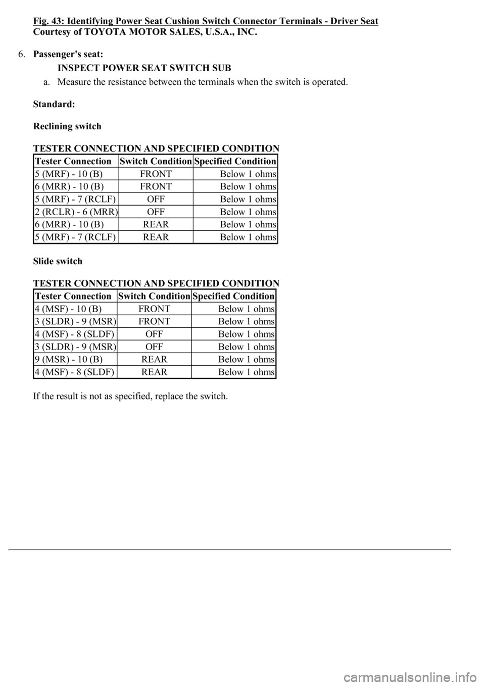
Fig. 43: Identifying Power Seat Cushion Switch Connector Terminals -Driver Seat
Courtesy of TOYOTA MOTOR SALES, U.S.A., INC.
6.Passenger's seat:
INSPECT POWER SEAT SWITCH SUB
a. Measure the resistance between the terminals when the switch is operated.
Standard:
Reclining switch
TESTER CONNECTION AND SPECIFIED CONDITION
Slide switch
TESTER CONNECTION AND SPECIFIED CONDITION
If the result is not as specified, replace the switch.
Tester ConnectionSwitch ConditionSpecified Condition
5 (MRF) - 10 (B)FRONTBelow 1 ohms
6 (MRR) - 10 (B)FRONTBelow 1 ohms
5 (MRF) - 7 (RCLF)OFFBelow 1 ohms
2 (RCLR) - 6 (MRR)OFFBelow 1 ohms
6 (MRR) - 10 (B)REARBelow 1 ohms
5 (MRF) - 7 (RCLF)REARBelow 1 ohms
Tester ConnectionSwitch ConditionSpecified Condition
4 (MSF) - 10 (B)FRONTBelow 1 ohms
3 (SLDR) - 9 (MSR)FRONTBelow 1 ohms
4 (MSF) - 8 (SLDF)OFFBelow 1 ohms
3 (SLDR) - 9 (MSR)OFFBelow 1 ohms
9 (MSR) - 10 (B)REARBelow 1 ohms
4 (MSF) - 8 (SLDF)REARBelow 1 ohms
Page 3983 of 4500
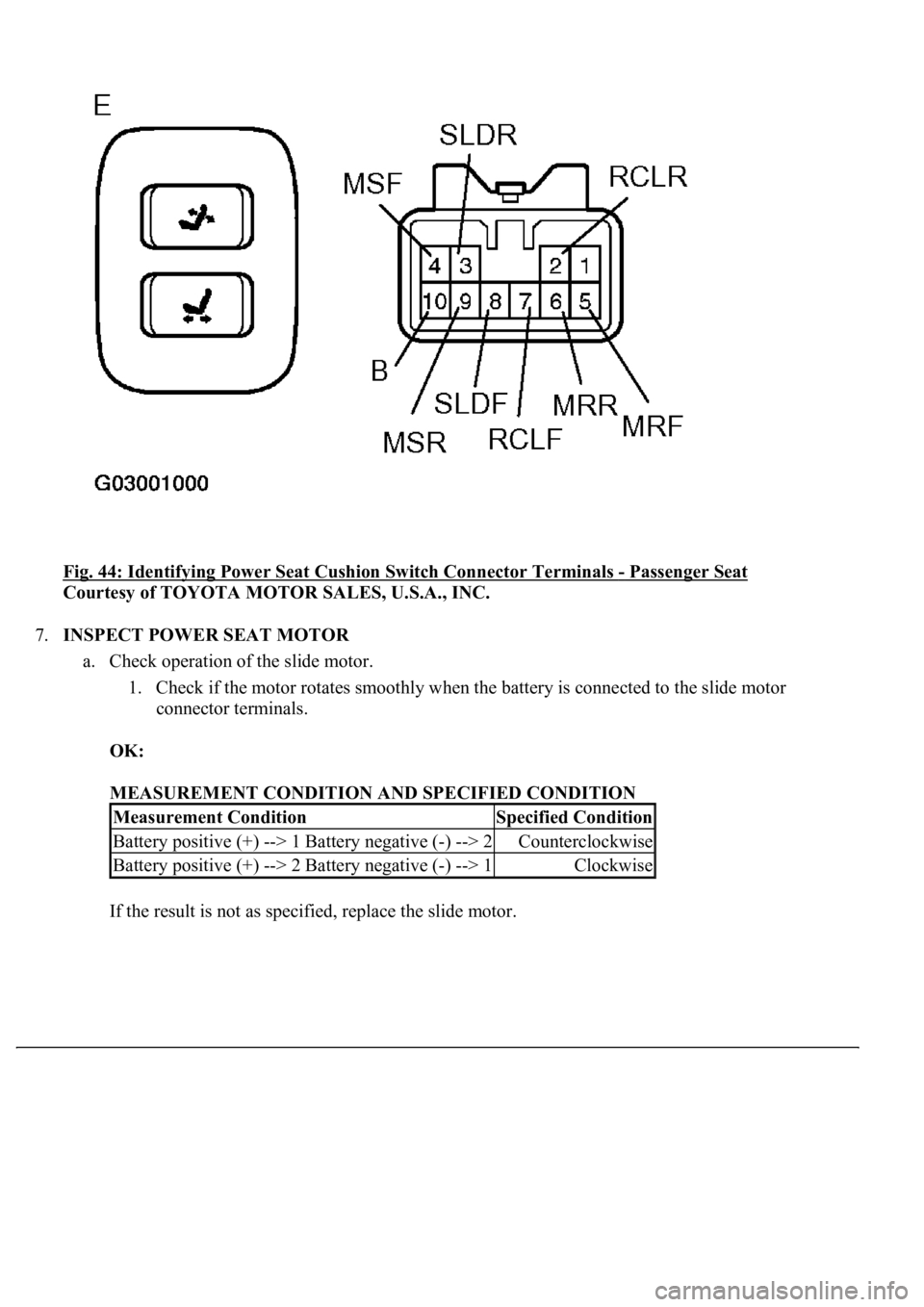
Fig. 44: Identifying Power Seat Cushion Switch Connector Terminals - Passenger Seat
Courtesy of TOYOTA MOTOR SALES, U.S.A., INC.
7.INSPECT POWER SEAT MOTOR
a. Check operation of the slide motor.
1. Check if the motor rotates smoothly when the battery is connected to the slide motor
connector terminals.
OK:
MEASUREMENT CONDITION AND SPECIFIED CONDITION
If the result is not as specified, replace the slide motor.
Measurement ConditionSpecified Condition
Battery positive (+) --> 1 Battery negative (-) --> 2Counterclockwise
Battery positive (+) --> 2 Battery negative (-) --> 1Clockwise
Page 4079 of 4500
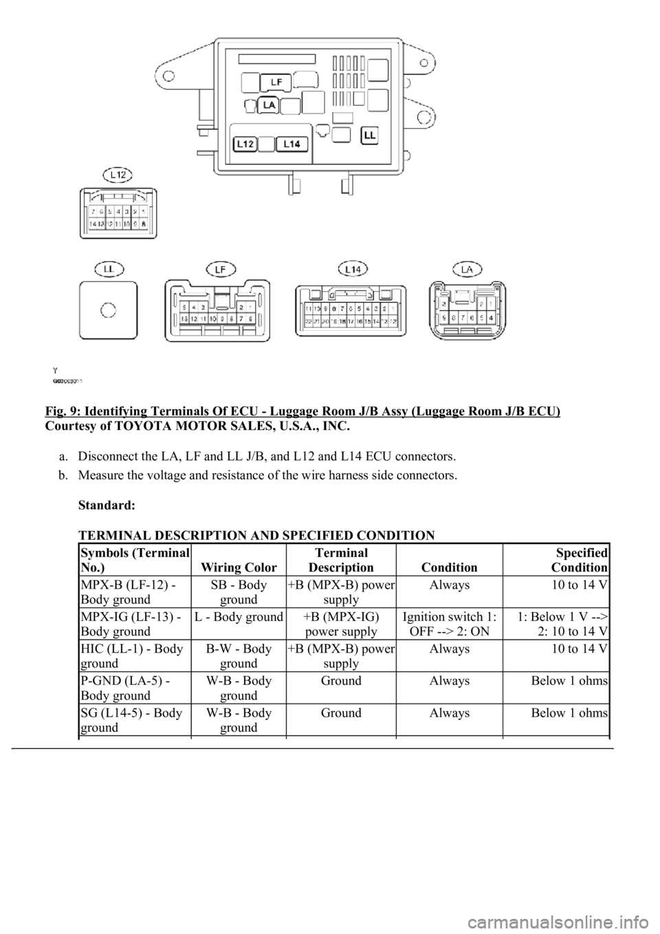
Fig. 9: Identifying Terminals Of ECU - Luggage Room J/B Assy (Luggage Room J/B ECU)
Courtesy of TOYOTA MOTOR SALES, U.S.A., INC.
a. Disconnect the LA, LF and LL J/B, and L12 and L14 ECU connectors.
b. Measure the voltage and resistance of the wire harness side connectors.
Standard:
TERMINAL DESCRIPTION AND SPECIFIED CONDITION
Symbols (Terminal
No.)
Wiring Color
Terminal
Description
Condition
Specified
Condition
MPX-B (LF-12) -
Body groundSB - Body
ground+B (MPX-B) power
supplyAlways10 to 14 V
MPX-IG (LF-13) -
Body groundL - Body ground+B (MPX-IG)
power supplyIgnition switch 1:
OFF --> 2: ON1: Below 1 V -->
2: 10 to 14 V
HIC (LL-1) - Body
groundB-W - Body
ground+B (MPX-B) power
supplyAlways10 to 14 V
P-GND (LA-5) -
Body groundW-B - Body
groundGroundAlwaysBelow 1 ohms
SG (L14-5) - Body
groundW-B - Body
groundGroundAlwaysBelow 1 ohms
Page 4081 of 4500
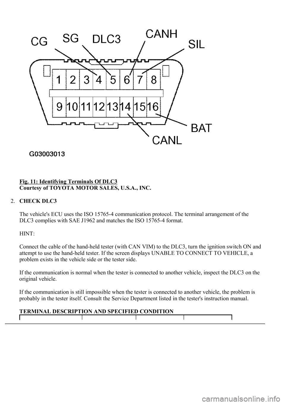
Fig. 11: Identifying Terminals Of DLC3
Courtesy of TOYOTA MOTOR SALES, U.S.A., INC.
2.CHECK DLC3
The vehicle's ECU uses the ISO 15765-4 communication protocol. The terminal arrangement of the
DLC3 complies with SAE J1962 and matches the ISO 15765-4 format.
HINT:
Connect the cable of the hand-held tester (with CAN VIM) to the DLC3, turn the ignition switch ON and
attempt to use the hand-held tester. If the screen displays UNABLE TO CONNECT TO VEHICLE, a
problem exists in the vehicle side or the tester side.
If the communication is normal when the tester is connected to another vehicle, inspect the DLC3 on the
original vehicle.
If the communication is still impossible when the tester is connected to another vehicle, the problem is
probably in the tester itself. Consult the Service Department listed in the tester's instruction manual.
TERMINAL DESCRIPTION AND SPECIFIED CONDITION
Page 4162 of 4500
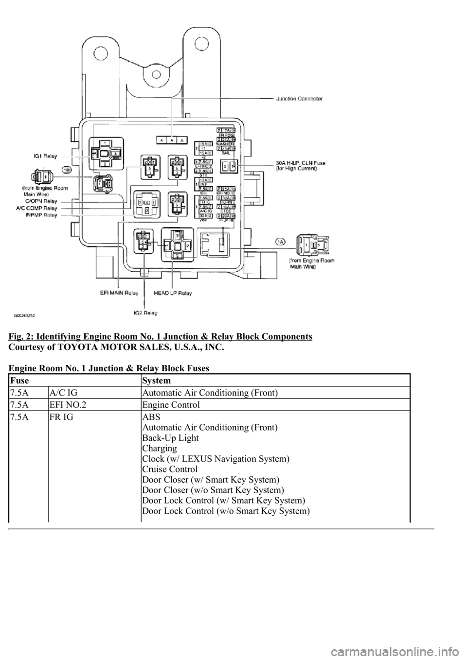
Fig. 2: Identifying Engine Room No. 1 Junction & Relay Block Components
Courtesy of TOYOTA MOTOR SALES, U.S.A., INC.
Engine Room No. 1 Junction & Relay Block Fuses
FuseSystem
7.5AA/C IGAutomatic Air Conditioning (Front)
7.5AEFI NO.2Engine Control
7.5AFR IGABS
Automatic Air Conditioning (Front)
Back-Up Light
Charging
Clock (w/ LEXUS Navigation System)
Cruise Control
Door Closer (w/ Smart Key System)
Door Closer (w/o Smart Key System)
Door Lock Control (w/ Smart Key System)
Door Lock Control (w/o Smart Key System)
Page 4166 of 4500
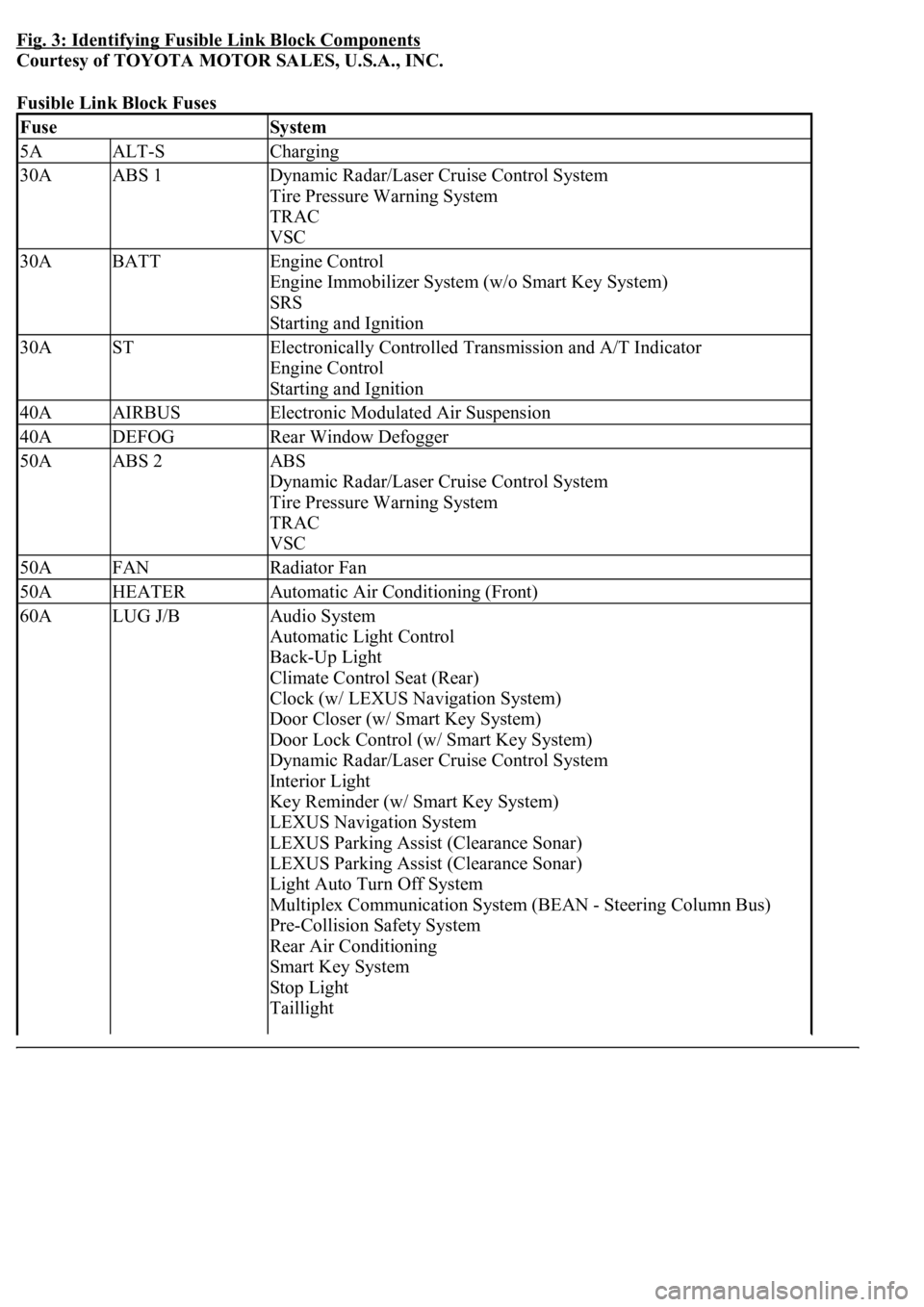
Fig. 3: Identifying Fusible Link Block Components
Courtesy of TOYOTA MOTOR SALES, U.S.A., INC.
Fusible Link Block Fuses
FuseSystem
5AALT-SCharging
30AABS 1Dynamic Radar/Laser Cruise Control System
Tire Pressure Warning System
TRAC
VSC
30ABATTEngine Control
Engine Immobilizer System (w/o Smart Key System)
SRS
Starting and Ignition
30ASTElectronically Controlled Transmission and A/T Indicator
Engine Control
Starting and Ignition
40AAIRBUSElectronic Modulated Air Suspension
40ADEFOGRear Window Defogger
50AABS 2ABS
Dynamic Radar/Laser Cruise Control System
Tire Pressure Warning System
TRAC
VSC
50AFANRadiator Fan
50AHEATERAutomatic Air Conditioning (Front)
60ALUG J/BAudio System
Automatic Light Control
Back-Up Light
Climate Control Seat (Rear)
Clock (w/ LEXUS Navigation System)
Door Closer (w/ Smart Key System)
Door Lock Control (w/ Smart Key System)
Dynamic Radar/Laser Cruise Control System
Interior Light
Key Reminder (w/ Smart Key System)
LEXUS Navigation System
LEXUS Parking Assist (Clearance Sonar)
LEXUS Parking Assist (Clearance Sonar)
Light Auto Turn Off System
Multiplex Communication System (BEAN - Steering Column Bus)
Pre-Collision Safety System
Rear Air Conditioning
Smart Key System
Stop Light
Taillight