LEXUS LS430 2003 Factory Repair Manual
LS430 2003
LEXUS
LEXUS
https://www.carmanualsonline.info/img/36/57050/w960_57050-0.png
LEXUS LS430 2003 Factory Repair Manual
Page 4197 of 4500
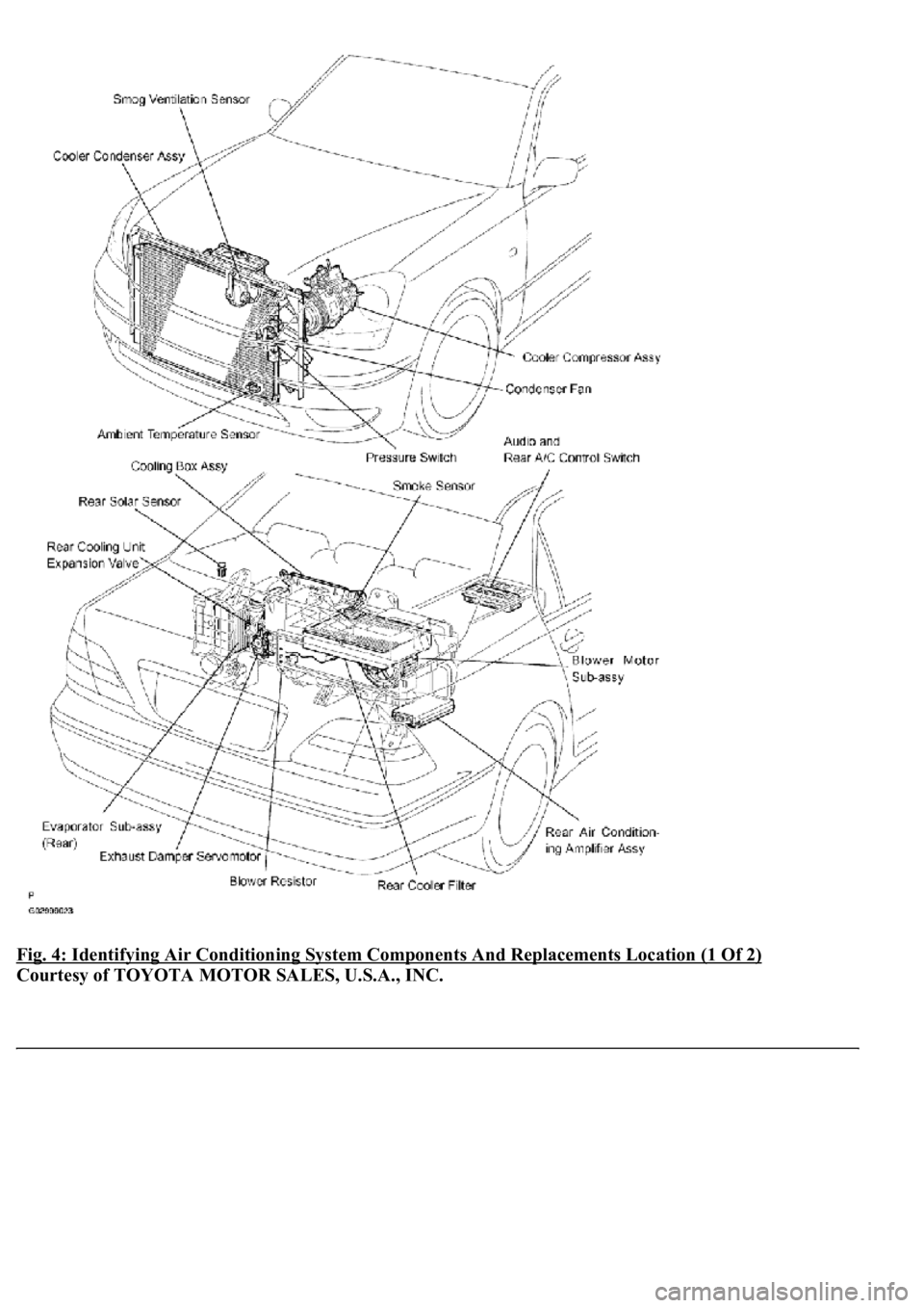
Fig. 4: Identifying Air Conditioning System Components And Replacements Location (1 Of 2)
Courtesy of TOYOTA MOTOR SALES, U.S.A., INC.
Page 4198 of 4500
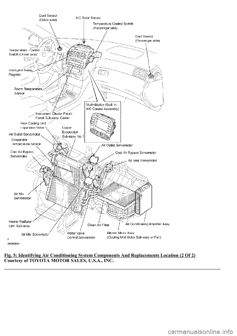
Fig. 5: Identifying Air Conditioning System Components And Replacements Location (2 Of 2)
Courtesy of TOYOTA MOTOR SALES, U.S.A., INC.
Page 4216 of 4500
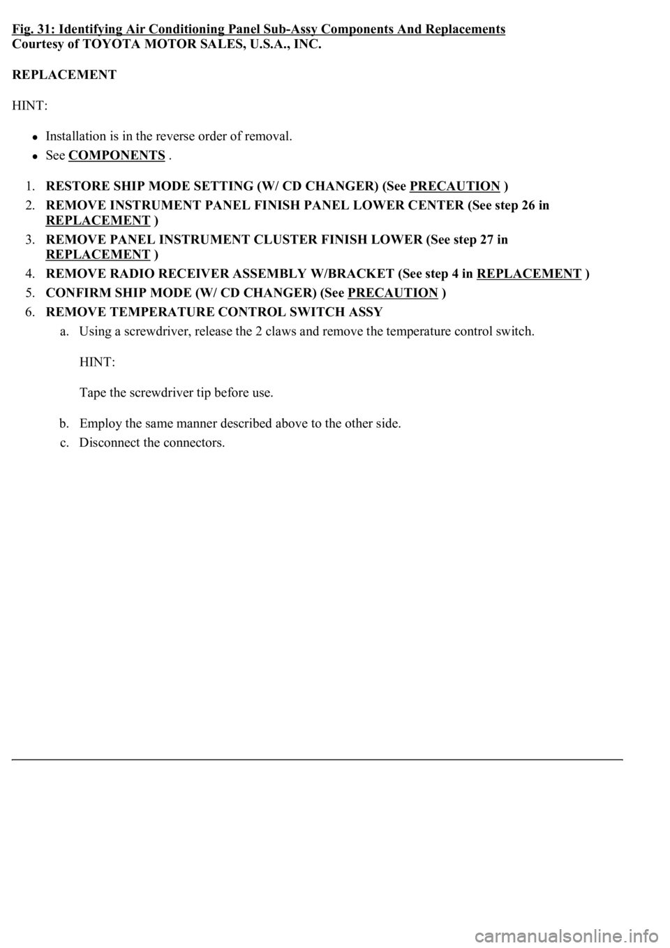
Fig. 31: Identifying Air Conditioning Panel Sub-Assy Components And Replacements
Courtesy of TOYOTA MOTOR SALES, U.S.A., INC.
REPLACEMENT
HINT:
Installation is in the reverse order of removal.
See COMPONENTS .
1.RESTORE SHIP MODE SETTING (W/ CD CHANGER) (See PRECAUTION
)
2.REMOVE INSTRUMENT PANEL FINISH PANEL LOWER CENTER (See step 26 in
REPLACEMENT
)
3.REMOVE PANEL INSTRUMENT CLUSTER FINISH LOWER (See step 27 in
REPLACEMENT
)
4.REMOVE RADIO RECEIVER ASSEMBLY W/BRACKET (See step 4 in REPLACEMENT
)
5.CONFIRM SHIP MODE (W/ CD CHANGER) (See PRECAUTION
)
6.REMOVE TEMPERATURE CONTROL SWITCH ASSY
a. Using a screwdriver, release the 2 claws and remove the temperature control switch.
HINT:
Tape the screwdriver tip before use.
b. Employ the same manner described above to the other side.
c. Disconnect the connectors.
Page 4225 of 4500
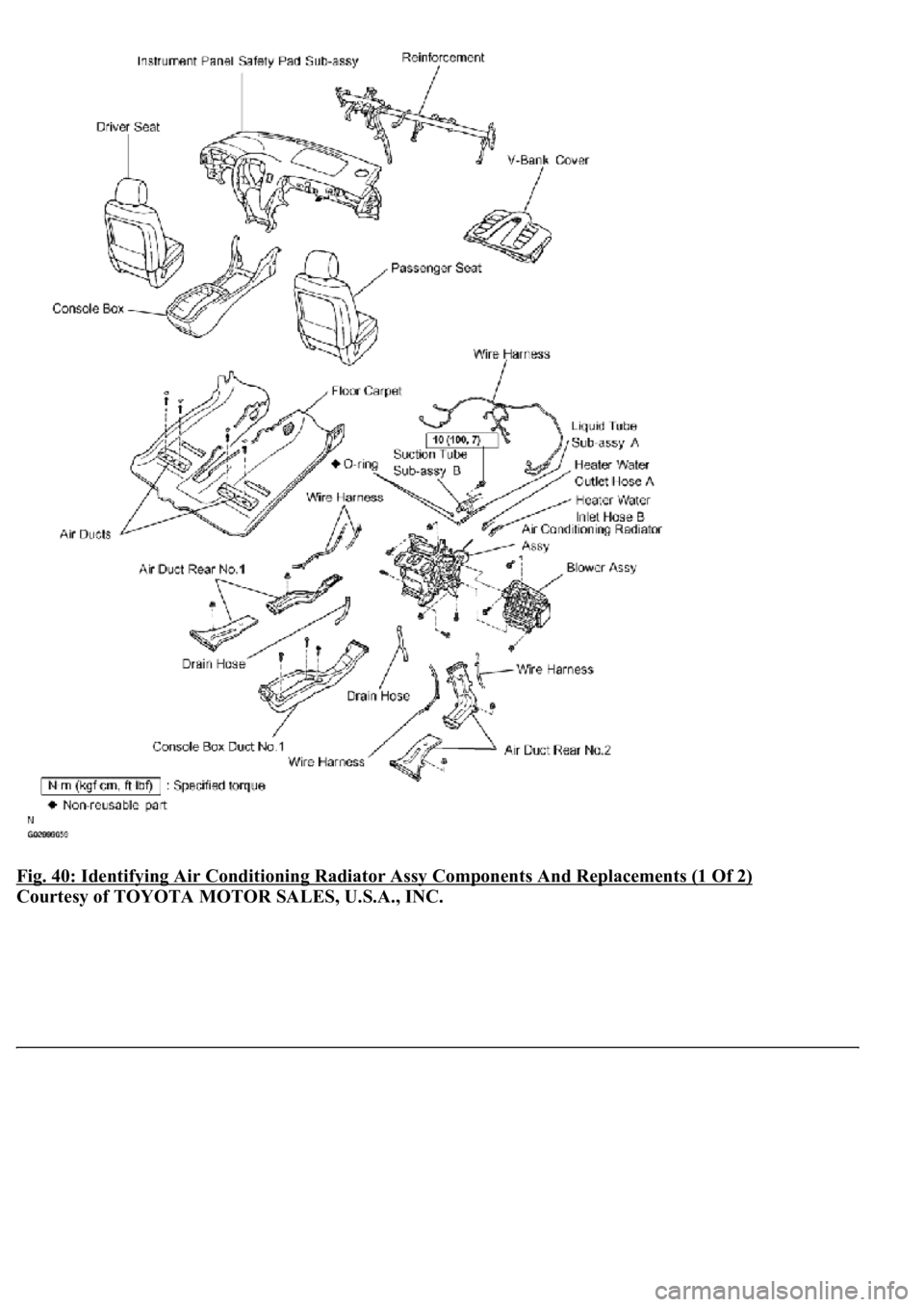
Fig. 40: Identifying Air Conditioning Radiator Assy Components And Replacements (1 Of 2)
Courtesy of TOYOTA MOTOR SALES, U.S.A., INC.
Page 4226 of 4500
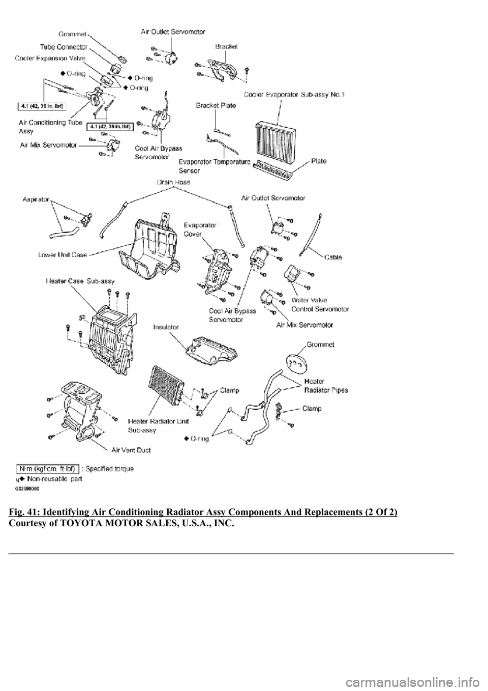
Fig. 41: Identifying Air Conditioning Radiator Assy Components And Replacements (2 Of 2)
Courtesy of TOYOTA MOTOR SALES, U.S.A., INC.
Page 4293 of 4500
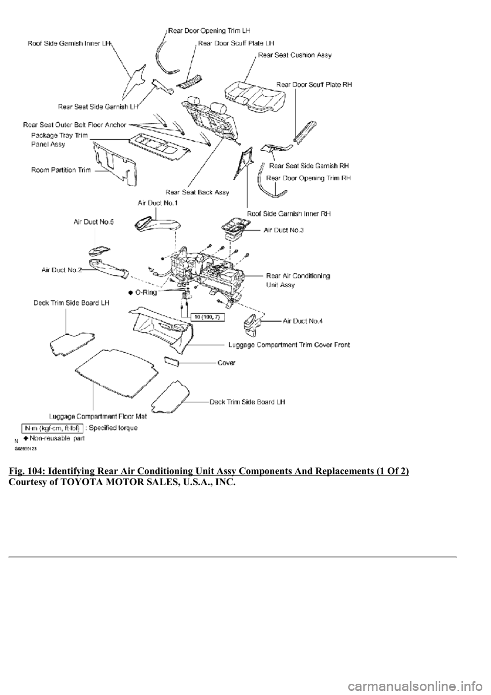
Fig. 104: Identifying Rear Air Conditioning Unit Assy Components And Replacements (1 Of 2)
Courtesy of TOYOTA MOTOR SALES, U.S.A., INC.
Page 4294 of 4500
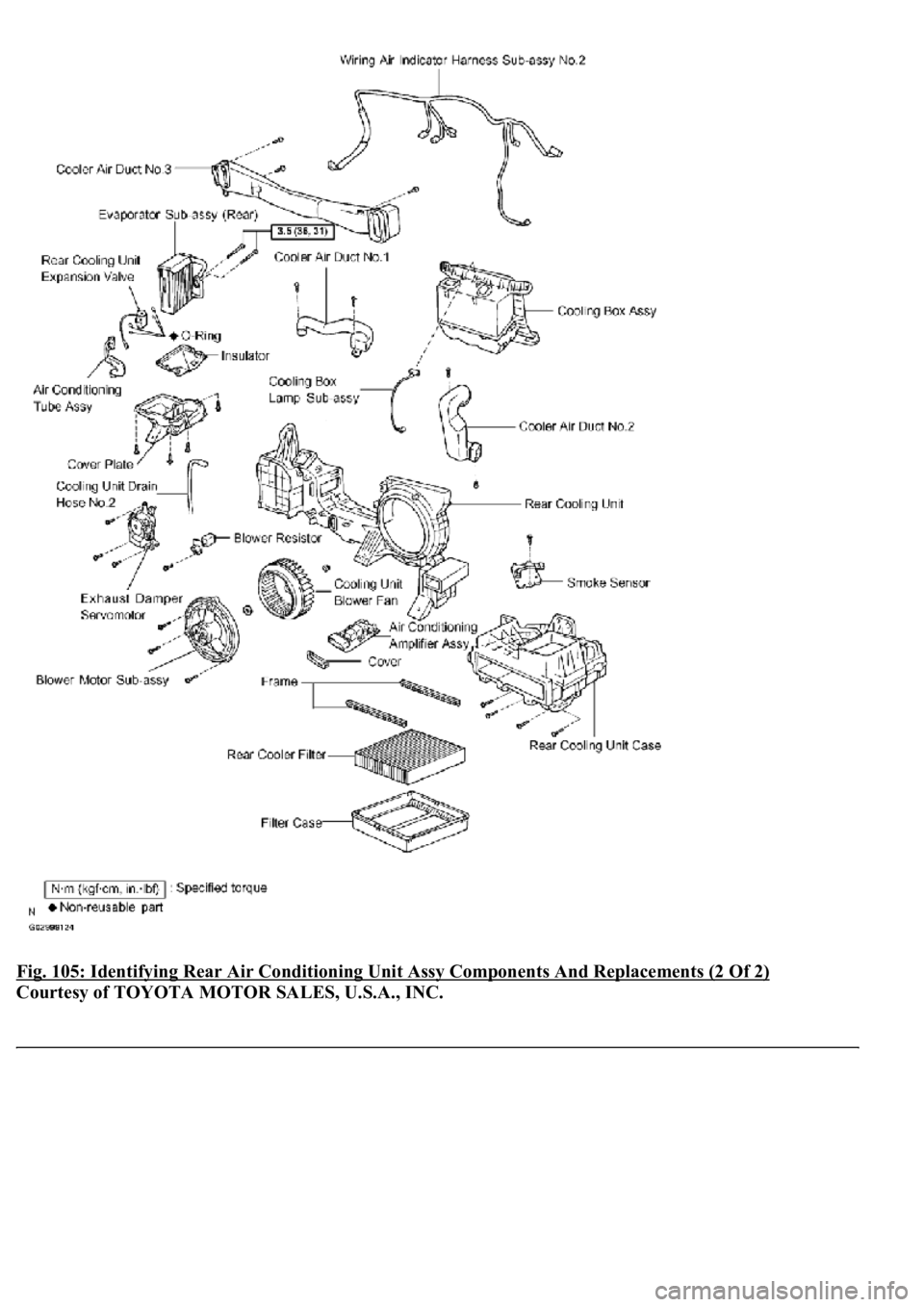
Fig. 105: Identifying Rear Air Conditioning Unit Assy Components And Replacements (2 Of 2)
Courtesy of TOYOTA MOTOR SALES, U.S.A., INC.
Page 4421 of 4500
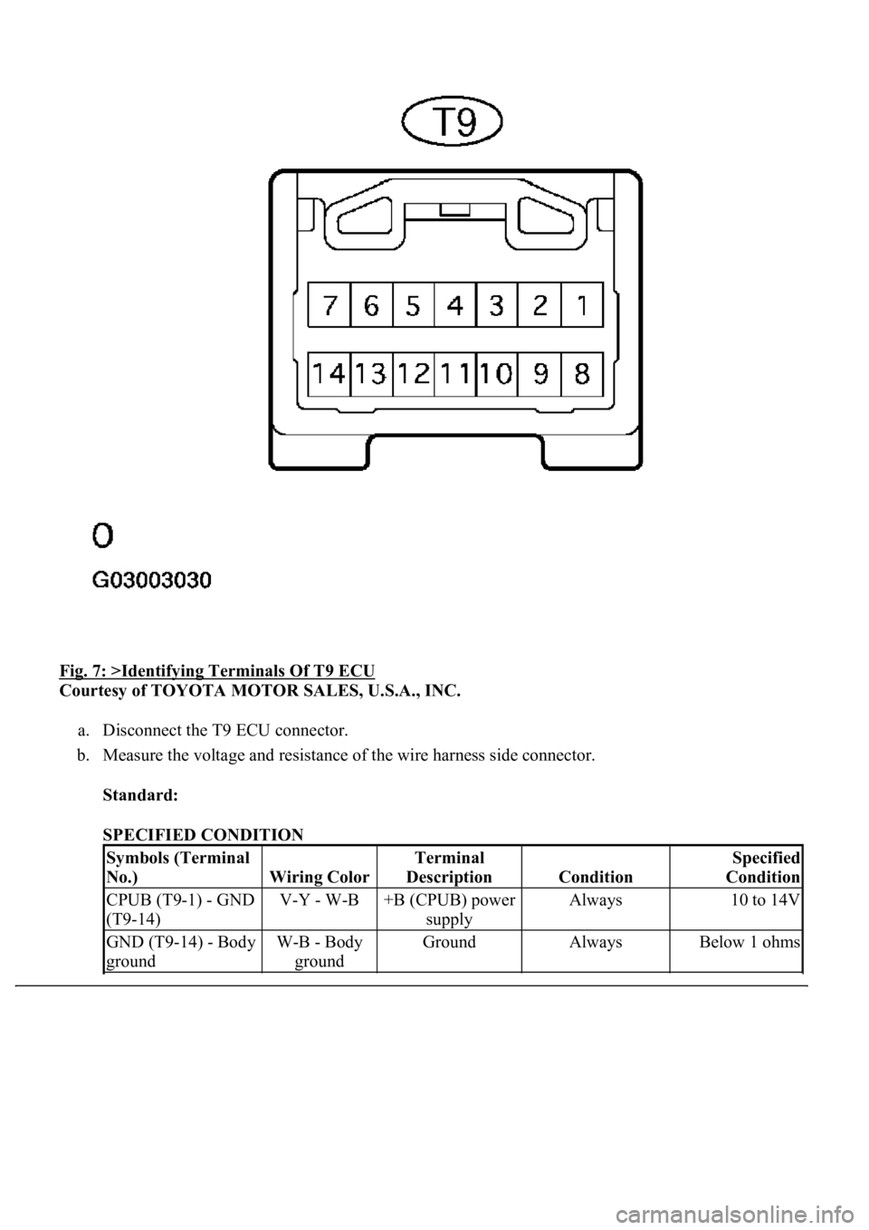
Fig. 7: >Identifying Terminals Of T9 ECU
Courtesy of TOYOTA MOTOR SALES, U.S.A., INC.
a. Disconnect the T9 ECU connector.
b. Measure the voltage and resistance of the wire harness side connector.
Standard:
SPECIFIED CONDITION
Symbols (Terminal
No.)
Wiring Color
Terminal
Description
Condition
Specified
Condition
CPUB (T9-1) - GND
(T9-14)V-Y - W-B+B (CPUB) power
supplyAlways10 to 14V
GND (T9-14) - Body
groundW-B - Body
groundGroundAlwaysBelow 1 ohms
Page 4423 of 4500
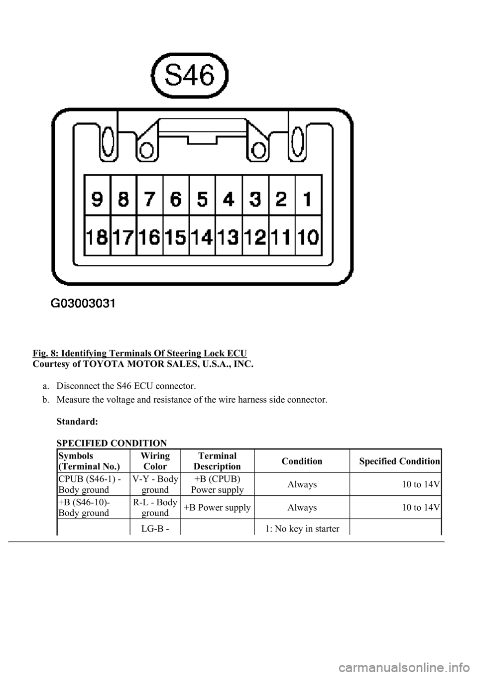
Fig. 8: Identifying Terminals Of Steering Lock ECU
Courtesy of TOYOTA MOTOR SALES, U.S.A., INC.
a. Disconnect the S46 ECU connector.
b. Measure the voltage and resistance of the wire harness side connector.
Standard:
SPECIFIED CONDITION
Symbols
(Terminal No.)Wiring
ColorTerminal
DescriptionConditionSpecified Condition
CPUB (S46-1) -
Body groundV-Y - Body
ground+B (CPUB)
Power supplyAlways10 to 14V
+B (S46-10)-
Body groundR-L - Body
ground+B Power supplyAlways10 to 14V
LG-B -1: No key in starter
Page 4424 of 4500
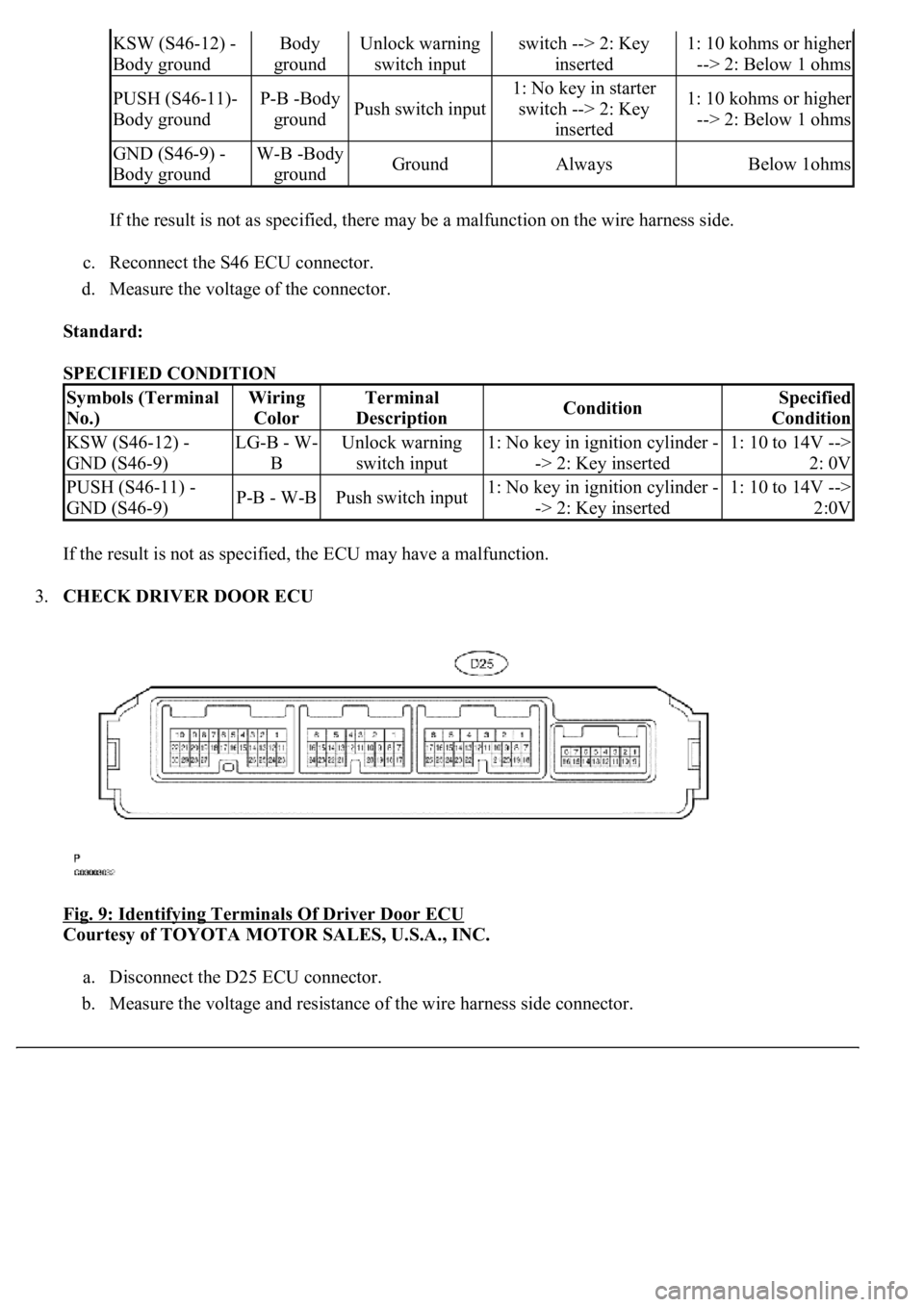
If the result is not as specified, there may be a malfunction on the wire harness side.
c. Reconnect the S46 ECU connector.
d. Measure the voltage of the connector.
Standard:
SPECIFIED CONDITION
If the result is not as specified, the ECU may have a malfunction.
3.CHECK DRIVER DOOR ECU
Fig. 9: Identifying Terminals Of Driver Door ECU
Courtesy of TOYOTA MOTOR SALES, U.S.A., INC.
a. Disconnect the D25 ECU connector.
b. Measure the voltage and resistance of the wire harness side connector.
KSW (S46-12) -
Body groundBody
groundUnlock warning
switch inputswitch --> 2: Key
inserted1: 10 kohms or higher
--> 2: Below 1 ohms
PUSH (S46-11)-
Body groundP-B -Body
groundPush switch input
1: No key in starter
switch --> 2: Key
inserted1: 10 kohms or higher
--> 2: Below 1 ohms
GND (S46-9) -
Body groundW-B -Body
groundGroundAlwaysBelow 1ohms
Symbols (Terminal
No.)Wiring
ColorTerminal
DescriptionConditionSpecified
Condition
KSW (S46-12) -
GND (S46-9)LG-B - W-
BUnlock warning
switch input1: No key in ignition cylinder -
-> 2: Key inserted1: 10 to 14V -->
2: 0V
PUSH (S46-11) -
GND (S46-9)P-B - W-BPush switch input1: No key in ignition cylinder -
-> 2: Key inserted1: 10 to 14V -->
2:0V
