fuse LEXUS LS430 2003 Factory Manual PDF
[x] Cancel search | Manufacturer: LEXUS, Model Year: 2003, Model line: LS430, Model: LEXUS LS430 2003Pages: 4500, PDF Size: 87.45 MB
Page 2213 of 4500
NG: REPLACE FUSE
OK: Go to Next Step.
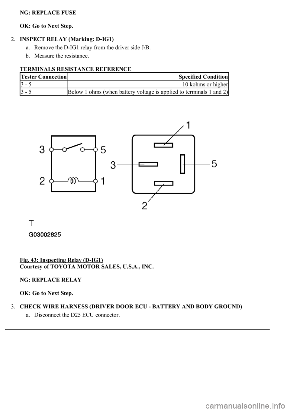
2.INSPECT RELAY (Marking: D-IG1)
a. Remove the D-IG1 relay from the driver side J/B.
b. Measure the resistance.
TERMINALS RESISTANCE REFERENCE
Fig. 43: Inspecting Relay (D
-IG1)
Courtesy of TOYOTA MOTOR SALES, U.S.A., INC.
NG: REPLACE RELAY
OK: Go to Next Step.
3.CHECK WIRE HARNESS (DRIVER DOOR ECU - BATTERY AND BODY GROUND)
a. Disconnect the D25 ECU connector.
Tester ConnectionSpecified Condition
3 - 510 kohms or higher
3 - 5Below 1 ohms (when battery voltage is applied to terminals 1 and 2)
Page 2216 of 4500
1.INSPECT FUSE (MPX-IG, AM1, P DOOR, MPX-B1, D/C CUT)
a. Remove the MPX-IG and AM1 fuses from the driver side J/B.
b. Remove the P DOOR and MPX-B1 fuses from the passenger side J/B.
c. Remove the D/C CUT fuse from the FL block assy.
d. Measure the resistance.
Standard: Below 1 ohms
NG: REPLACE FUSE
OK: Go to Next Step.
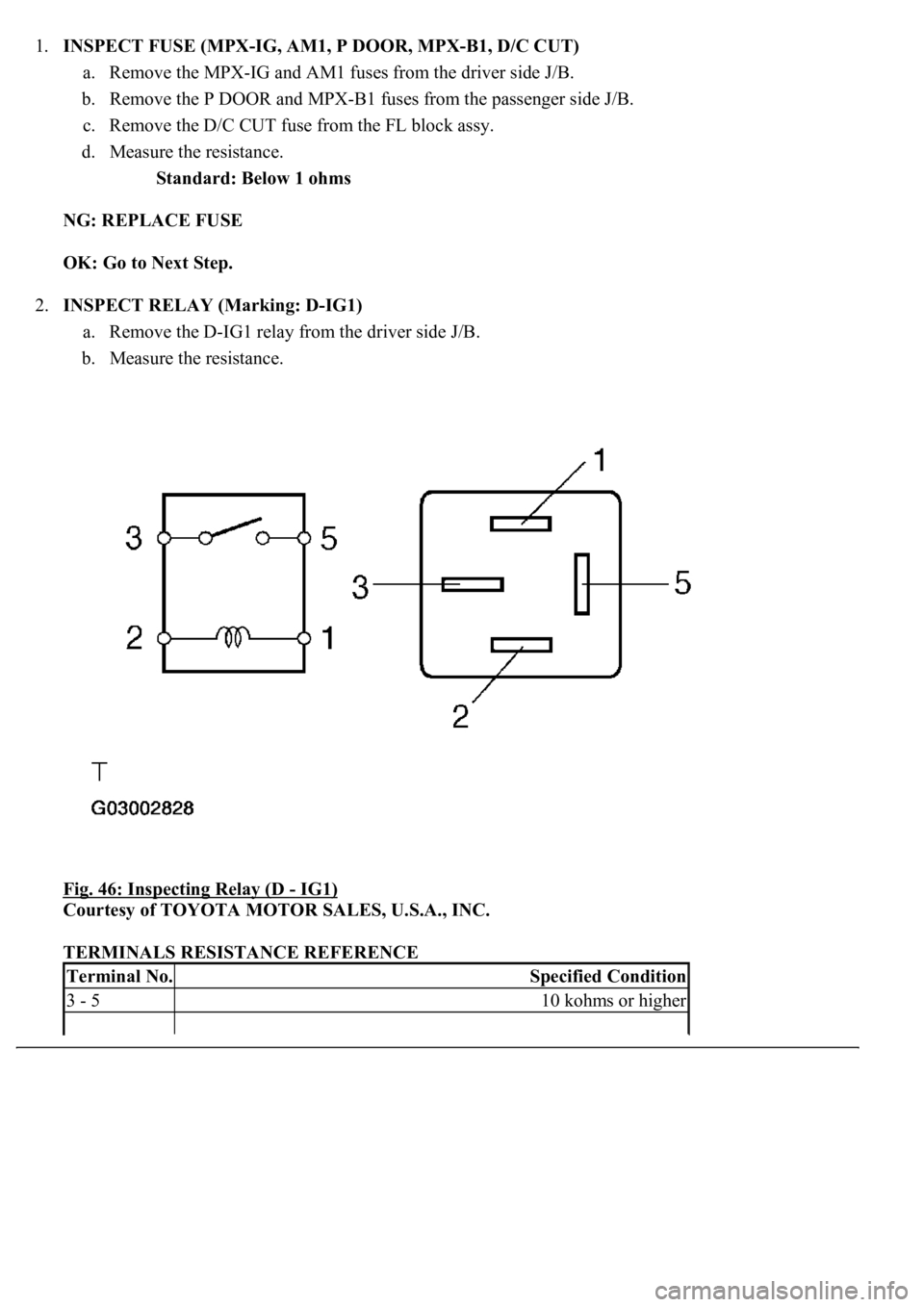
2.INSPECT RELAY (Marking: D-IG1)
a. Remove the D-IG1 relay from the driver side J/B.
b. Measure the resistance.
Fig. 46: Inspecting Relay (D
- IG1)
Courtesy of TOYOTA MOTOR SALES, U.S.A., INC.
TERMINALS RESISTANCE REFERENCE
Terminal No.Specified Condition
3 - 510 kohms or higher
Page 2219 of 4500
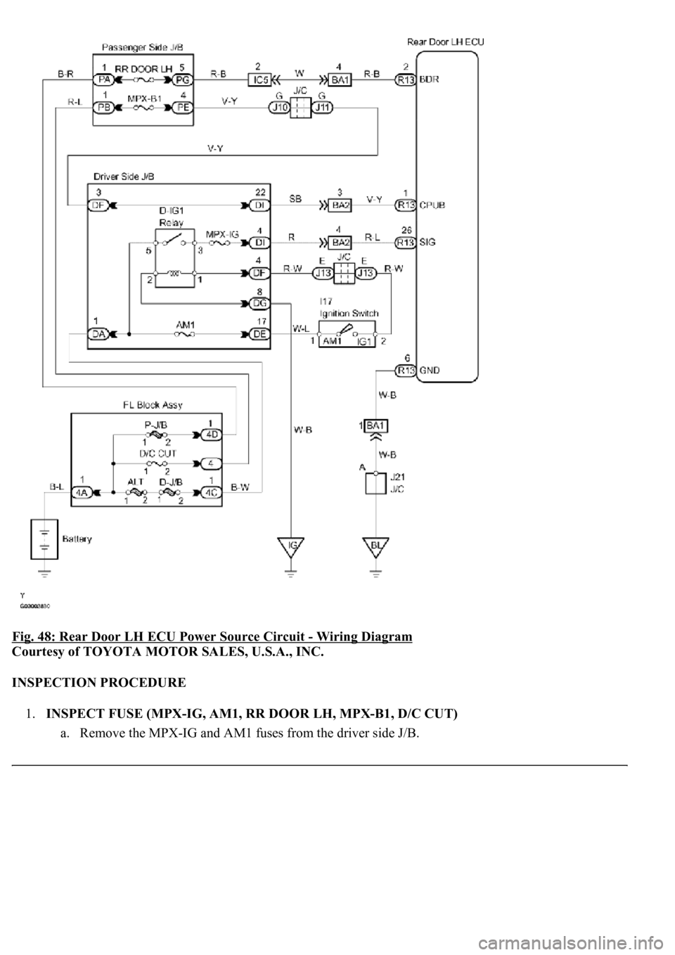
Fig. 48: Rear Door LH ECU Power Source Circuit - Wiring Diagram
Courtesy of TOYOTA MOTOR SALES, U.S.A., INC.
INSPECTION PROCEDURE
1.INSPECT FUSE (MPX-IG, AM1, RR DOOR LH, MPX-B1, D/C CUT)
a. Remove the MPX-IG and AM1 fuses from the driver side J/B.
Page 2220 of 4500
b. Remove the RR DOOR LH and MPX-B1 fuses from the passenger side J/B.
c. Remove the D/C CUT fuse from the FL block assy.
d. Measure the resistance.
Standard: Below 1 ohms
NG: REPLACE FUSE
OK: Go to Next Step.
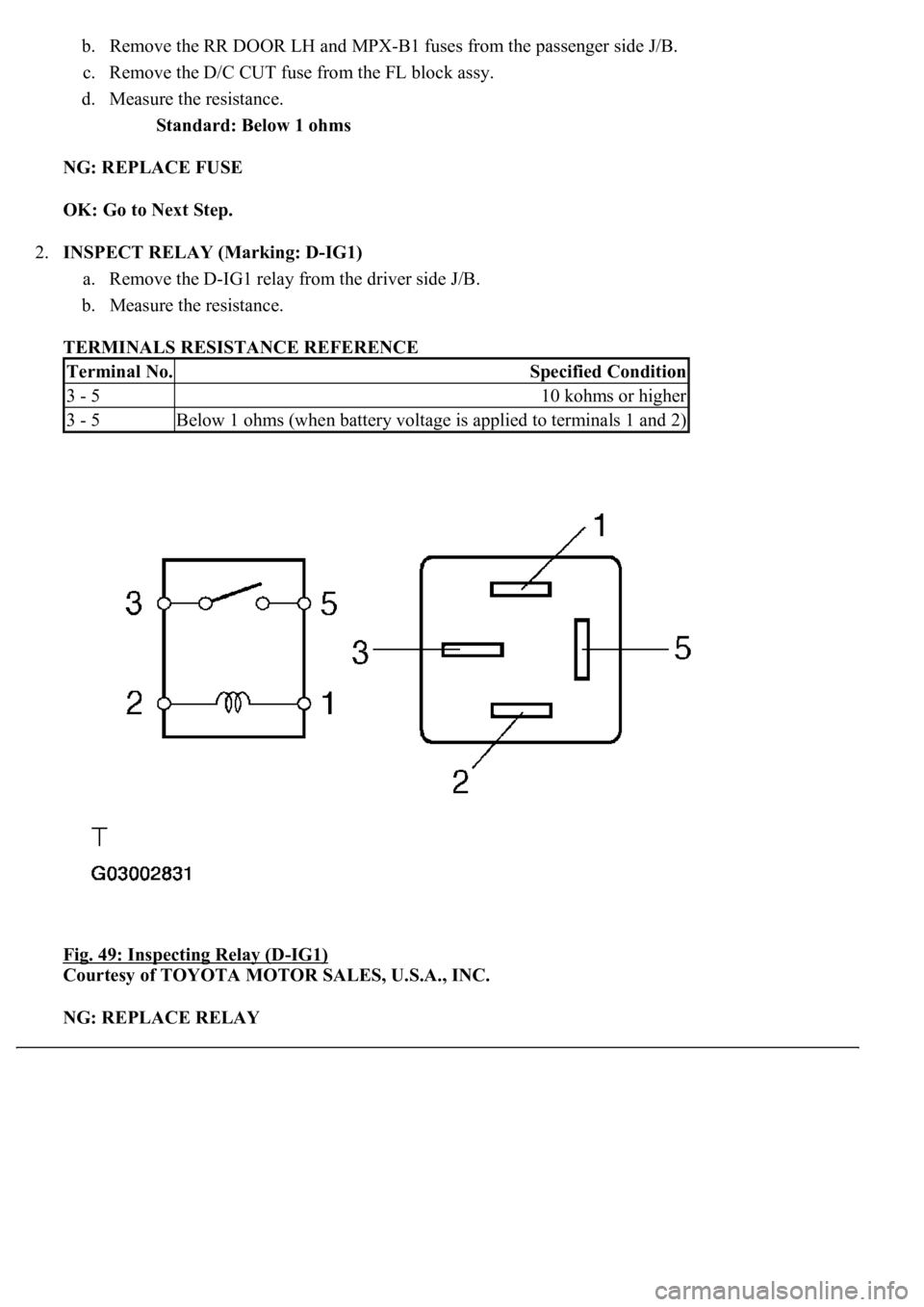
2.INSPECT RELAY (Marking: D-IG1)
a. Remove the D-IG1 relay from the driver side J/B.
b. Measure the resistance.
TERMINALS RESISTANCE REFERENCE
Fig. 49: Inspecting Relay (D
-IG1)
Courtesy of TOYOTA MOTOR SALES, U.S.A., INC.
NG: REPLACE RELAY
Terminal No.Specified Condition
3 - 510 kohms or higher
3 - 5Below 1 ohms (when battery voltage is applied to terminals 1 and 2)
Page 2223 of 4500
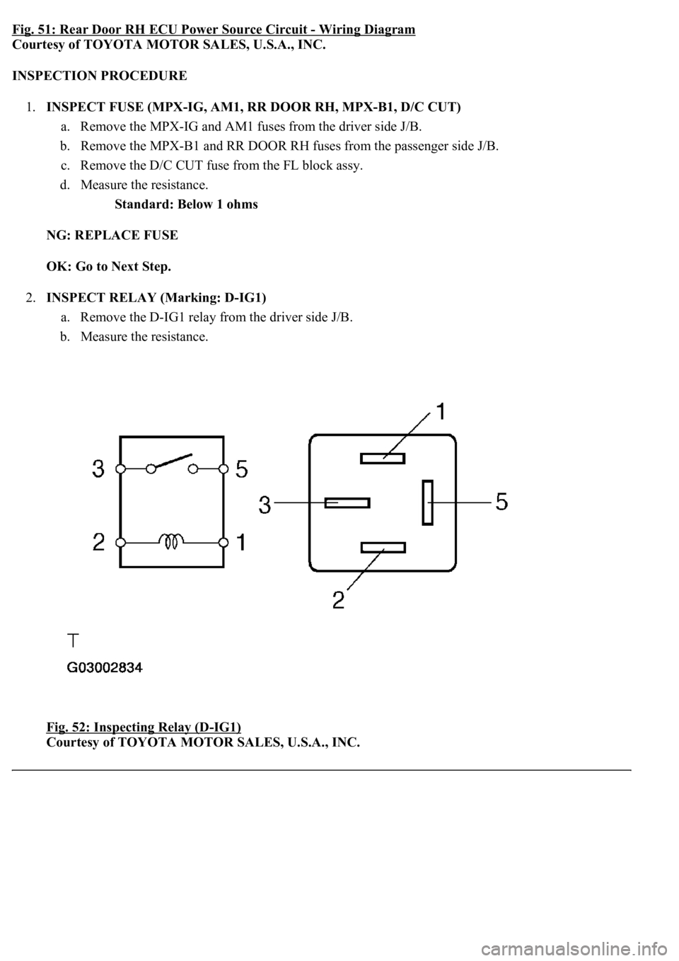
Fig. 51: Rear Door RH ECU Power Source Circuit -Wiring Diagram
Courtesy of TOYOTA MOTOR SALES, U.S.A., INC.
INSPECTION PROCEDURE
1.INSPECT FUSE (MPX-IG, AM1, RR DOOR RH, MPX-B1, D/C CUT)
a. Remove the MPX-IG and AM1 fuses from the driver side J/B.
b. Remove the MPX-B1 and RR DOOR RH fuses from the passenger side J/B.
c. Remove the D/C CUT fuse from the FL block assy.
d. Measure the resistance.
Standard: Below 1 ohms
NG: REPLACE FUSE
OK: Go to Next Step.
2.INSPECT RELAY (Marking: D-IG1)
a. Remove the D-IG1 relay from the driver side J/B.
b. Measure the resistance.
Fig. 52: Inspecting Relay (D
-IG1)
Courtesy of TOYOTA MOTOR SALES, U.S.A., INC.
Page 2450 of 4500
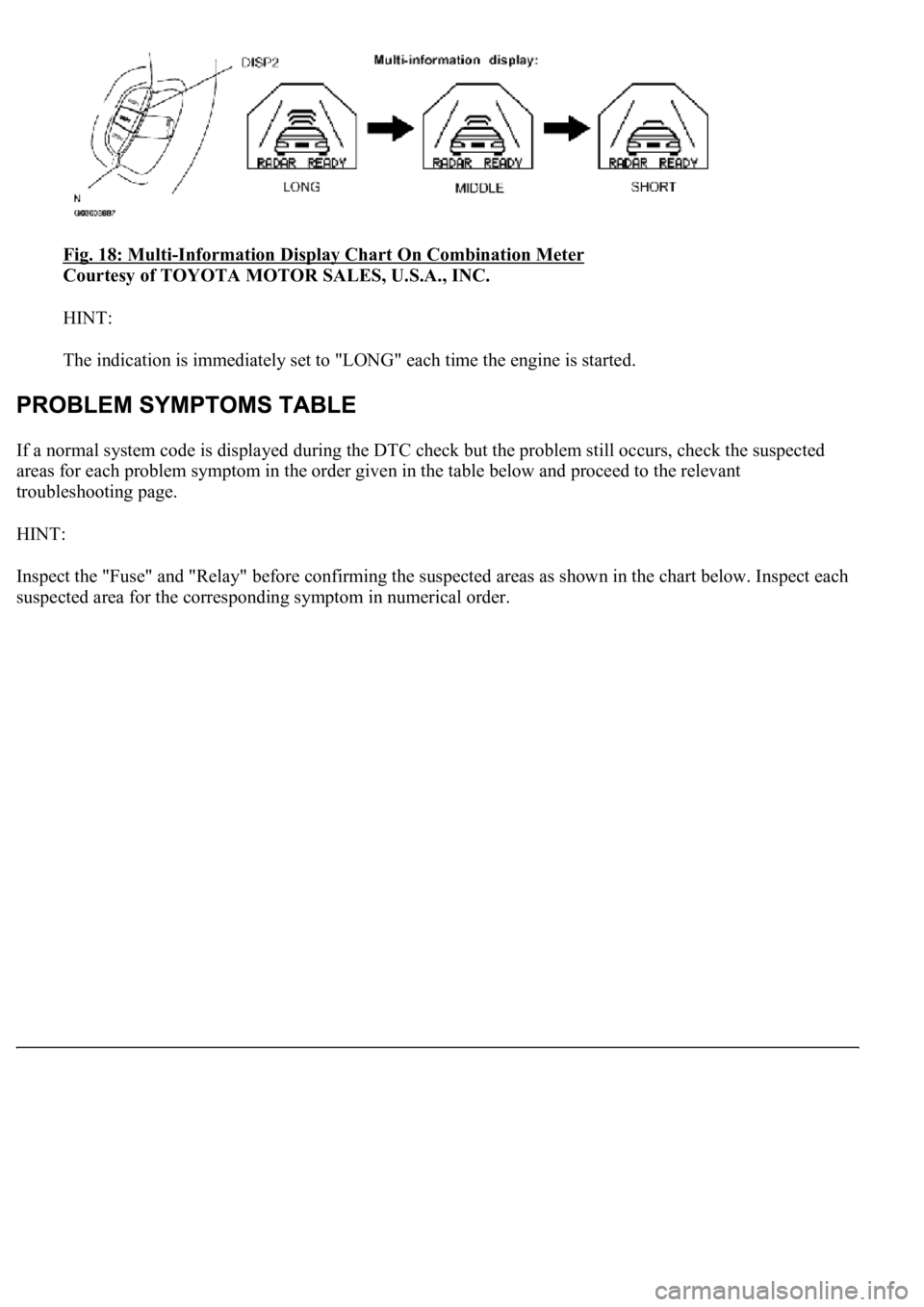
Fig. 18: Multi-Information Display Chart On Combination Meter
Courtesy of TOYOTA MOTOR SALES, U.S.A., INC.
HINT:
The indication is immediately set to "LONG" each time the engine is started.
If a normal system code is displayed during the DTC check but the problem still occurs, check the suspected
areas for each problem symptom in the order given in the table below and proceed to the relevant
troubleshooting page.
HINT:
Inspect the "Fuse" and "Relay" before confirming the suspected areas as shown in the chart below. Inspect each
suspected area for the correspondin
g symptom in numerical order.
Page 2472 of 4500
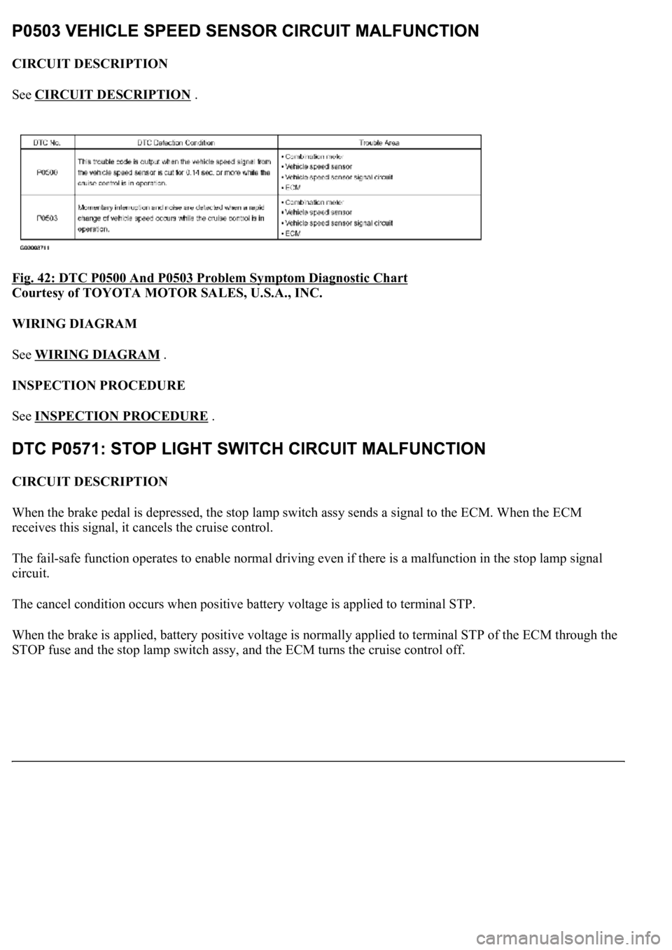
CIRCUIT DESCRIPTION
See CIRCUIT DESCRIPTION
.
Fig. 42: DTC P0500 And P0503 Problem Symptom Diagnostic Chart
Courtesy of TOYOTA MOTOR SALES, U.S.A., INC.
WIRING DIAGRAM
See WIRING DIAGRAM
.
INSPECTION PROCEDURE
See INSPECTION PROCEDURE
.
CIRCUIT DESCRIPTION
When the brake pedal is depressed, the stop lamp switch assy sends a signal to the ECM. When the ECM
receives this signal, it cancels the cruise control.
The fail-safe function operates to enable normal driving even if there is a malfunction in the stop lamp signal
circuit.
The cancel condition occurs when positive battery voltage is applied to terminal STP.
When the brake is applied, battery positive voltage is normally applied to terminal STP of the ECM through the
STOP fuse and the stop lamp switch ass
y, and the ECM turns the cruise control off.
Page 2550 of 4500
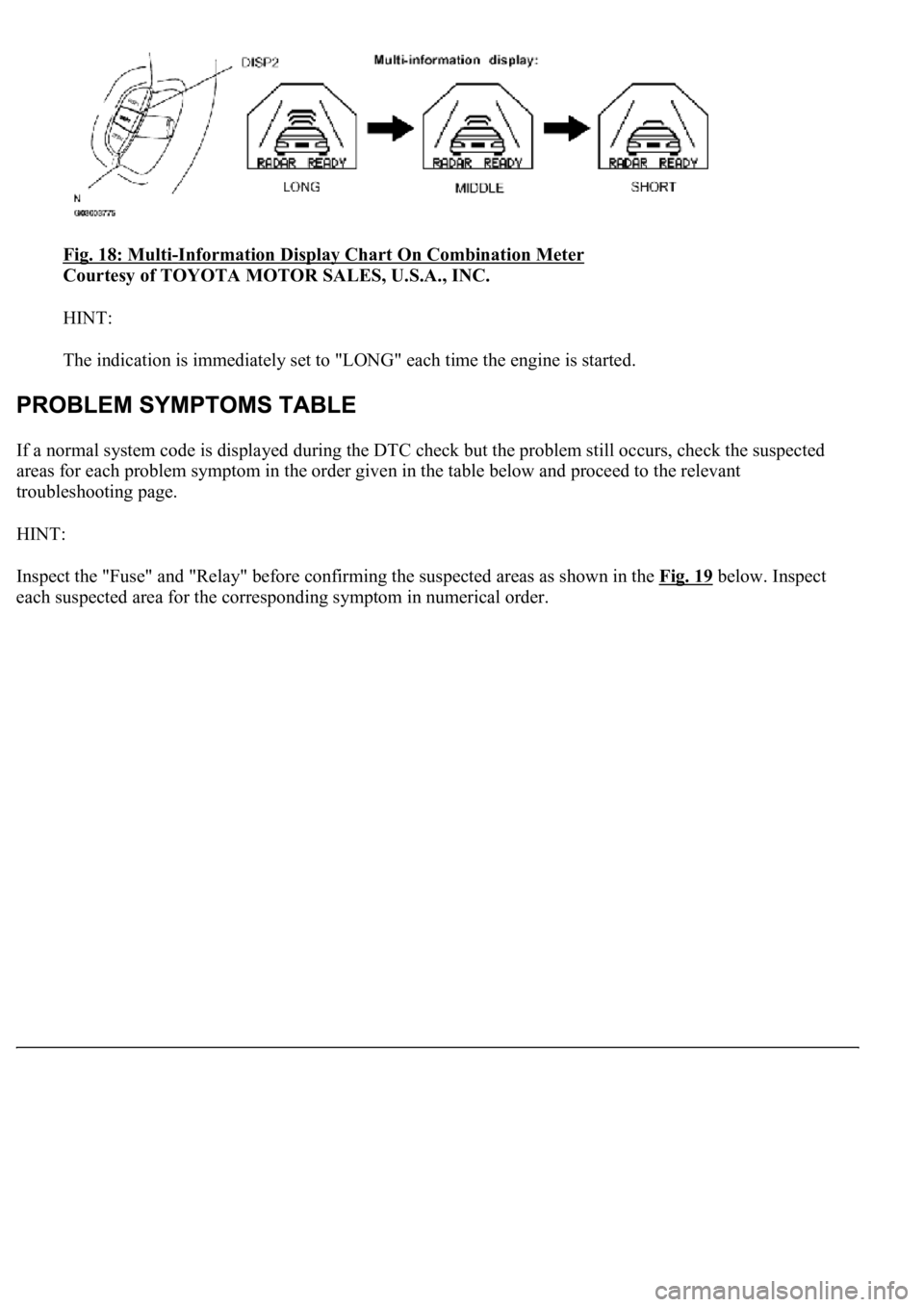
Fig. 18: Multi-Information Display Chart On Combination Meter
Courtesy of TOYOTA MOTOR SALES, U.S.A., INC.
HINT:
The indication is immediately set to "LONG" each time the engine is started.
If a normal system code is displayed during the DTC check but the problem still occurs, check the suspected
areas for each problem symptom in the order given in the table below and proceed to the relevant
troubleshooting page.
HINT:
Inspect the "Fuse" and "Relay" before confirming the suspected areas as shown in the Fig. 19
below. Inspect
each suspected area for the correspondin
g symptom in numerical order.
Page 2573 of 4500
CIRCUIT DESCRIPTION
SEE CIRCUIT DESCRIPTION
.
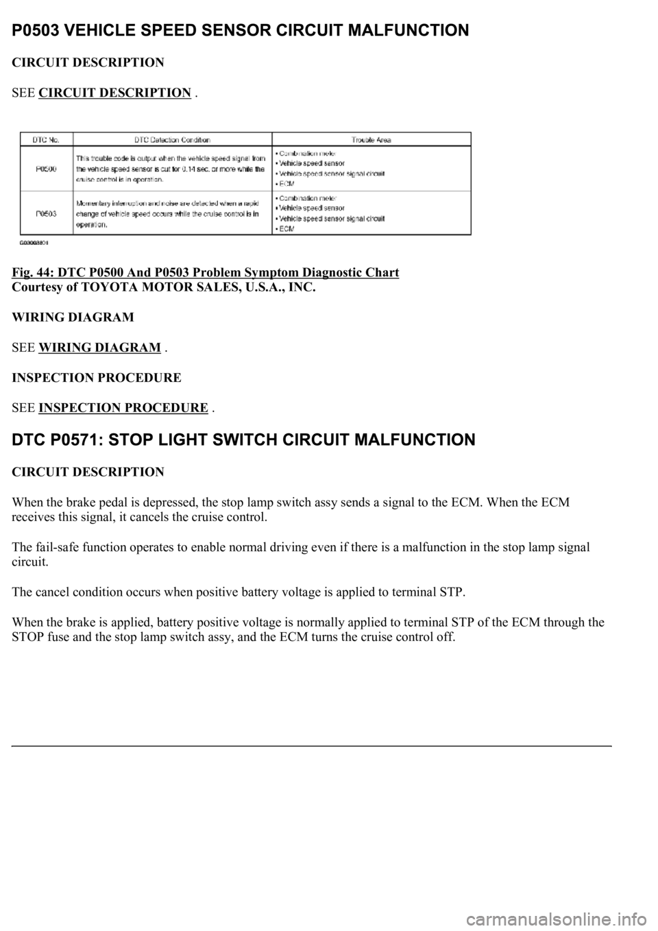
Fig. 44: DTC P0500 And P0503 Problem Symptom Diagnostic Chart
Courtesy of TOYOTA MOTOR SALES, U.S.A., INC.
WIRING DIAGRAM
SEE WIRING DIAGRAM
.
INSPECTION PROCEDURE
SEE INSPECTION PROCEDURE
.
CIRCUIT DESCRIPTION
When the brake pedal is depressed, the stop lamp switch assy sends a signal to the ECM. When the ECM
receives this signal, it cancels the cruise control.
The fail-safe function operates to enable normal driving even if there is a malfunction in the stop lamp signal
circuit.
The cancel condition occurs when positive battery voltage is applied to terminal STP.
When the brake is applied, battery positive voltage is normally applied to terminal STP of the ECM through the
STOP fuse and the stop lamp switch ass
y, and the ECM turns the cruise control off.
Page 3222 of 4500
Courtesy of TOYOTA MOTOR SALES, U.S.A., INC.
INSPECTION PROCEDURE
1.INSPECT FUSE (MPX-B1, AM2, STR LOCK, D/C CUT)
a. Remove the MPX-B1, AM2 and STR LOCK fuses from the passenger side J/B.
b. Remove the D/C CUT fuse from the FL block.
c. Measure the resistance of the fuse.
Standard: Below 1 ohms
NG: REPLACE FUSE
OK: Go to next step
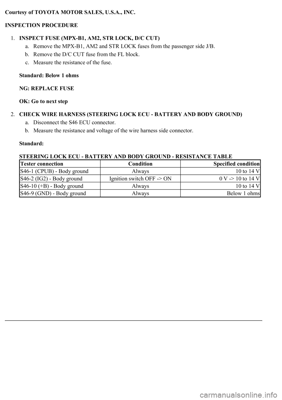
2.CHECK WIRE HARNESS (STEERING LOCK ECU - BATTERY AND BODY GROUND)
a. Disconnect the S46 ECU connector.
b. Measure the resistance and voltage of the wire harness side connector.
Standard:
STEERING LOCK ECU - BATTERY AND BODY GROUND - RESISTANCE TABLE
Tester connectionConditionSpecified condition
S46-1 (CPUB) - Body groundAlways10 to 14 V
S46-2 (IG2) - Body groundIgnition switch OFF -> ON0 V -> 10 to 14 V
S46-10 (+B) - Body groundAlways10 to 14 V
S46-9 (GND) - Body groundAlwaysBelow 1 ohms