LEXUS LS430 2003 Factory Repair Manual
LS430 2003
LEXUS
LEXUS
https://www.carmanualsonline.info/img/36/57050/w960_57050-0.png
LEXUS LS430 2003 Factory Repair Manual
Page 48 of 4500
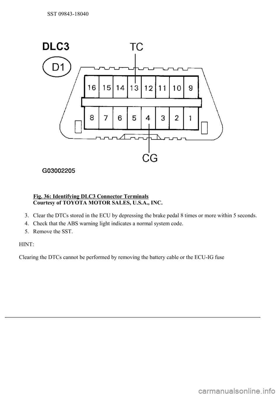
SST 09843-18040
Fig. 36: Identifying DLC3 Connector Terminals
Courtesy of TOYOTA MOTOR SALES, U.S.A., INC.
3. Clear the DTCs stored in the ECU by depressing the brake pedal 8 times or more within 5 seconds.
4. Check that the ABS warning light indicates a normal system code.
5. Remove the SST.
HINT:
Clearin
g the DTCs cannot be performed by removing the battery cable or the ECU-IG fuse
Page 89 of 4500
VEHICLE CONDITION / TEST DETAILS DESCRIPTION
OK: Go to next step
<0037004b00480003005200530048005500440057004c0052005100030056005200580051004700030052004900030057004b0048000300240025003600030050005200570052005500030056004b00520058004f00470003004500480003004b0048004400
5500470011[
NG: Go to step 2
OK: REPLACE ABS & TRACTION ACTUATOR ASSY (SEE REPLACEMENT
)
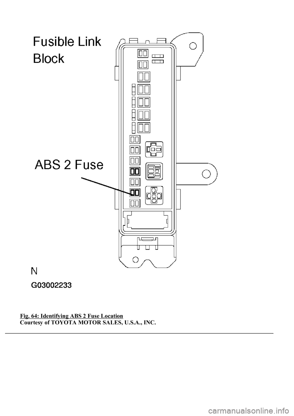
2.INSPECT FUSE (ABS2 FUSE)
a. Remove the ABS 2 fuse from fusible link block.
b. Measure the resistance according to the value (s) in the table below.
Standard:
ABS 2 FUSE DESCRIPTION
ItemVehicle Condition / Test DetailsVehicle Condition / Test Details
ABS MOT RELAYTurns ABS motor relay / ON or OFFON: Motor relay ON
ABS 2 FuseBelow 1 ohms (Continuity)
Page 90 of 4500
Fig. 64: Identifying ABS 2 Fuse Location
Courtesy of TOYOTA MOTOR SALES, U.S.A., INC.
Page 91 of 4500
NG: CHECK FOR SHORT IN ALL HARNESS AND CONNECTOR CONNECTED TO FUSE
AND REPLACE FUSE
OK: Go to next step
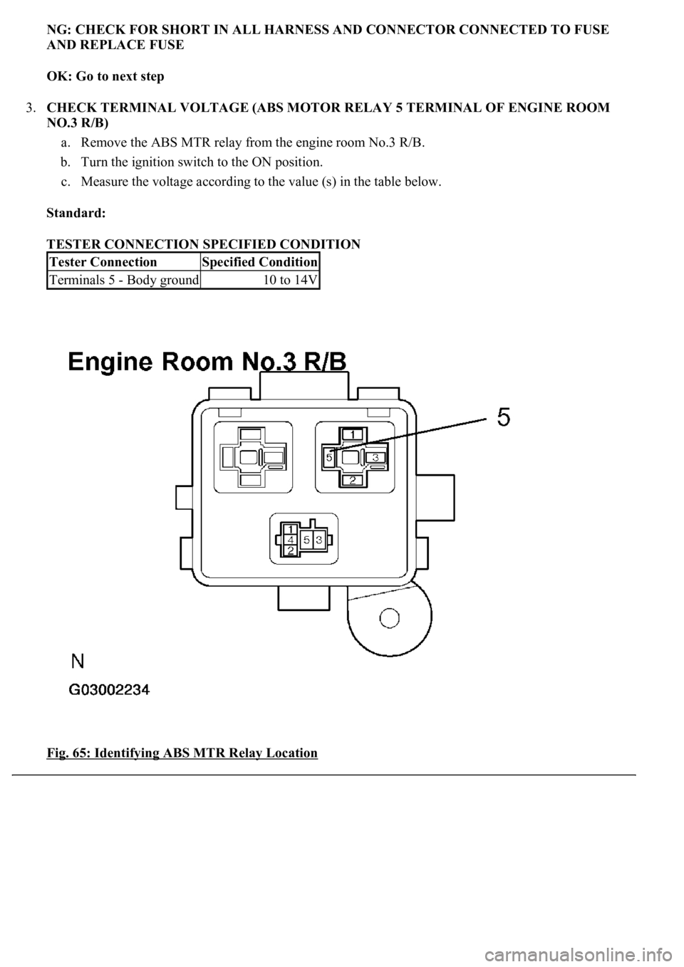
3.CHECK TERMINAL VOLTAGE (ABS MOTOR RELAY 5 TERMINAL OF ENGINE ROOM
NO.3 R/B)
a. Remove the ABS MTR relay from the engine room No.3 R/B.
b. Turn the ignition switch to the ON position.
c. Measure the voltage according to the value (s) in the table below.
Standard:
TESTER CONNECTION SPECIFIED CONDITION
Fig. 65: Identifying ABS MTR Relay Location
Tester ConnectionSpecified Condition
Terminals 5 - Body ground10 to 14V
Page 98 of 4500
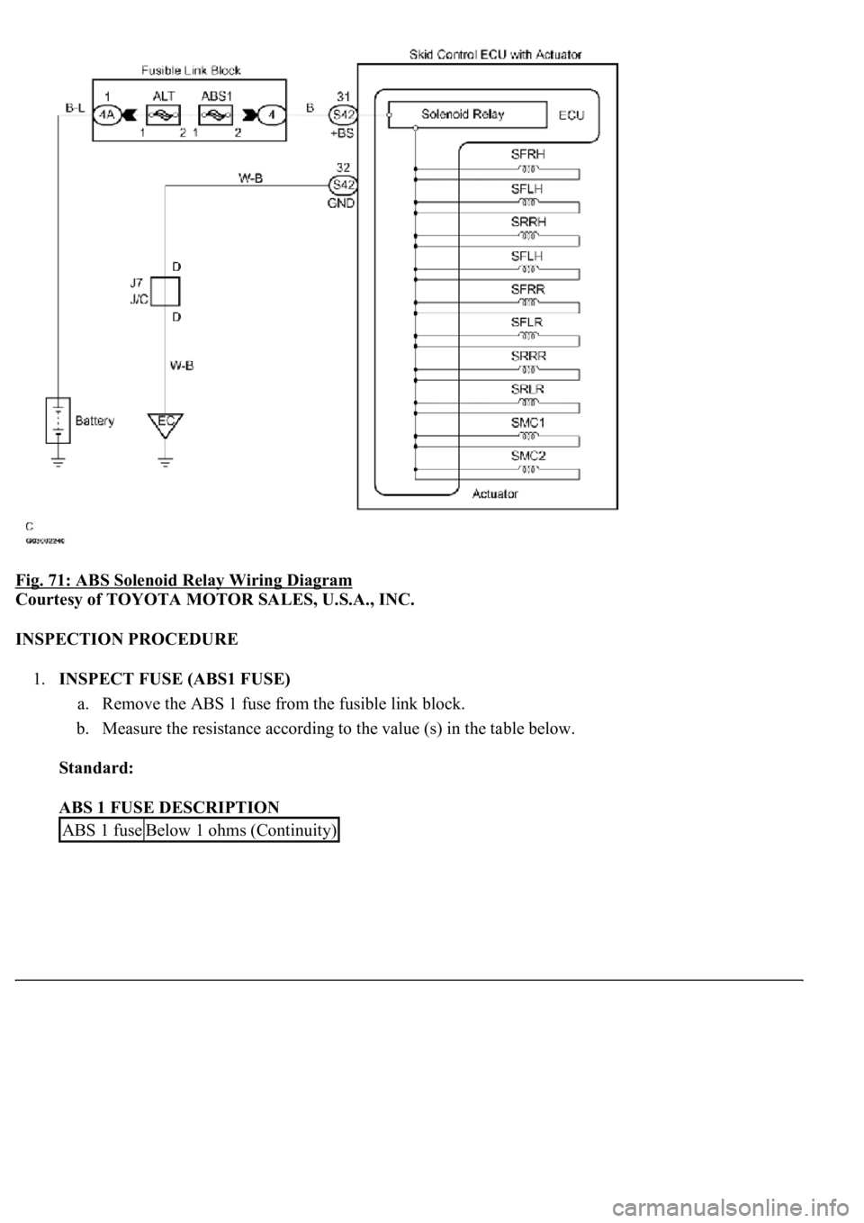
Fig. 71: ABS Solenoid Relay Wiring Diagram
Courtesy of TOYOTA MOTOR SALES, U.S.A., INC.
INSPECTION PROCEDURE
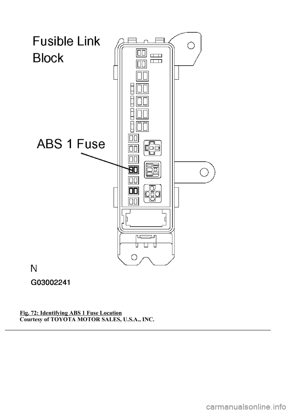
1.INSPECT FUSE (ABS1 FUSE)
a. Remove the ABS 1 fuse from the fusible link block.
b. Measure the resistance according to the value (s) in the table below.
Standard:
ABS 1 FUSE DESCRIPTION
ABS 1 fuseBelow 1 ohms (Continuity)
Page 99 of 4500
Fig. 72: Identifying ABS 1 Fuse Location
Courtesy of TOYOTA MOTOR SALES, U.S.A., INC.
Page 100 of 4500
NG: CHECK FOR SHORT IN ALL HARNESS AND CONNECTOR CONNECTED TO FUSE
AND REPLACE FUSE
OK: Go to next step
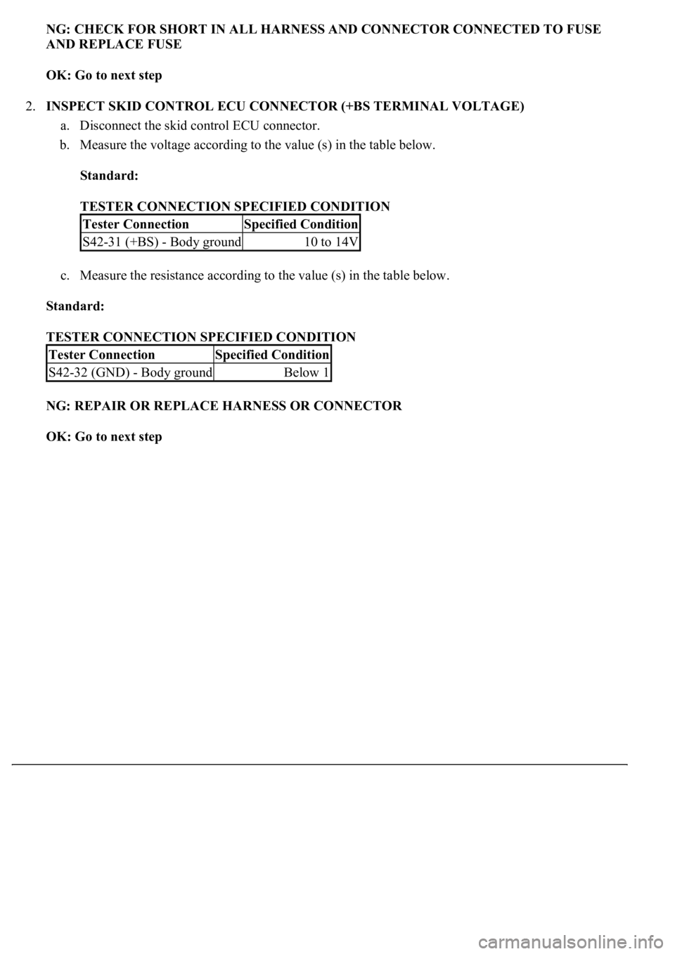
2.INSPECT SKID CONTROL ECU CONNECTOR (+BS TERMINAL VOLTAGE)
a. Disconnect the skid control ECU connector.
b. Measure the voltage according to the value (s) in the table below.
Standard:
TESTER CONNECTION SPECIFIED CONDITION
c. Measure the resistance according to the value (s) in the table below.
Standard:
TESTER CONNECTION SPECIFIED CONDITION
NG: REPAIR OR REPLACE HARNESS OR CONNECTOR
OK: Go to next step
Tester ConnectionSpecified Condition
S42-31 (+BS) - Body ground10 to 14V
Tester ConnectionSpecified Condition
S42-32 (GND) - Body groundBelow 1
Page 123 of 4500
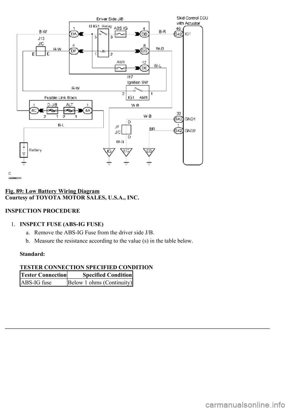
Fig. 89: Low Battery Wiring Diagram
Courtesy of TOYOTA MOTOR SALES, U.S.A., INC.
INSPECTION PROCEDURE
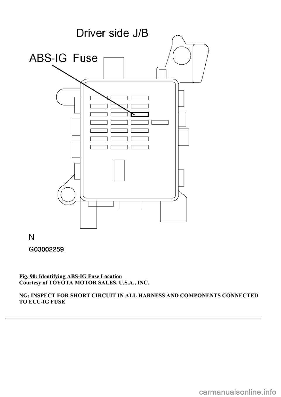
1.INSPECT FUSE (ABS-IG FUSE)
a. Remove the ABS-IG Fuse from the driver side J/B.
b. Measure the resistance according to the value (s) in the table below.
Standard:
TESTER CONNECTION SPECIFIED CONDITION
Tester ConnectionSpecified Condition
ABS-IG fuseBelow 1 ohms (Continuity)
Page 124 of 4500
Fig. 90: Identifying ABS-IG Fuse Location
Courtesy of TOYOTA MOTOR SALES, U.S.A., INC.
NG: INSPECT FOR SHORT CIRCUIT IN ALL HARNESS AND COMPONENTS CONNECTED
TO ECU-IG FUSE
Page 400 of 4500
Courtesy of TOYOTA MOTOR SALES, U.S.A., INC.
INSPECTION PROCEDURE
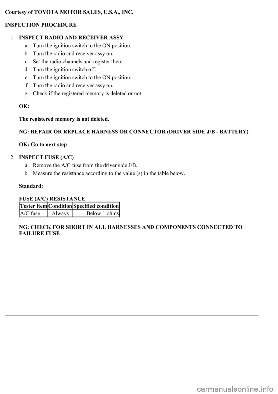
1.INSPECT RADIO AND RECEIVER ASSY
a. Turn the ignition switch to the ON position.
b. Turn the radio and receiver assy on.
c. Set the radio channels and register them.
d. Turn the ignition switch off.
e. Turn the ignition switch to the ON position.
f. Turn the radio and receiver assy on.
g. Check if the registered memory is deleted or not.
OK:
The registered memory is not deleted.
NG: REPAIR OR REPLACE HARNESS OR CONNECTOR (DRIVER SIDE J/B - BATTERY)
OK: Go to next step
2.INSPECT FUSE (A/C)
a. Remove the A/C fuse from the driver side J/B.
b. Measure the resistance according to the value (s) in the table below.
Standard:
FUSE (A/C) RESISTANCE
NG: CHECK FOR SHORT IN ALL HARNESSES AND COMPONENTS CONNECTED TO
FAILURE FUSE
Tester itemConditionSpecified condition
A/C fuseAlwaysBelow 1 ohms
