ECO mode LEXUS LS430 2006 Owners Manual
[x] Cancel search | Manufacturer: LEXUS, Model Year: 2006, Model line: LS430, Model: LEXUS LS430 2006Pages: 419, PDF Size: 11.19 MB
Page 43 of 419
27
1-3. Adjustable components
1
Before driving
■Recalling the driving position
Driver’s seat position, head restraint height, seat cushion length, shoulder
belt height, and ou
tside rear view mirrors are adjus ted to memorized
position when you unlock the driver’s door with the wireless remote con-
trol or the smart access system, if equipped.
The tilt and telescopic steering column position is ad justed to the memo-
rized position when you push the ignitio n switch, or inser
t the key into the
key slot depending on the model.
■ Er
asing the previous memory
Close the driver’s door and select the ignition switch in OFF posi-
tion and remove the key.
Push the “SET” button and the “LOCK” or “UNLOCK” button at the same time for about one second until you hear two beeps.
■To change the memorized position
Adjust the desired positions of the driver ’
s seat, tilt and telescopic steering
column and outside mirrors.
Push the “SET” button and the “1”, “2” or “3” button at the same time until
you hear a beep.
■Retained accessory power operation
Memorized positions (except for the tilt a
nd telescopic steering column) can be
activated within 30 seconds after the driver’s door is opened, even if the ignition
switch is turned off.
■If any position memory button is push ed while the adjustments are being made
The operation will stop. To reactivate the sy stem
, push the desired button (“1”, “2” or
“3”) again.
Page 60 of 419
44
1-3. Adjustable components
■Side mirror operating conditions
The ignition switch must b
e turned to ACC or ON.
■When the mirrors are fogged up
Turn on the mirror heaters to defog the mirrors. ( P.
1 7 0 )
■Ignition switch integrated automatic operation
If the AUTO indicator light is on, the mirrors are in automatic operation mode.
• If the ignition switch is in the ACC or ON position, the rear view mirrors are
automatically extended and folded, if the ignition switch is turned to the
OFF position.
CAUTION
■When driving the vehicle
Observe the following precautions while driving.
Failing to do so may result in losing control of the vehicle and cause an accident,
r
esulting in serious injury or even death.
• Do not adjust the mirror while driving.
• Do not drive with the mirrors folded backward.
• Both the driver and passenger side rear view mirrors must be extended and pr
operly adjusted before driving.
■When the mirror heaters are operating
Do not touch the mirror surface, as the mirror surface becomes hot.
NOTICE
■If the mirror gets icy
Do not scrape the mirror face. Use a spray de-icer to de-ice the mirror.
Page 71 of 419
55
1
1-6. Theft deterrent system
Before driving
Alarm
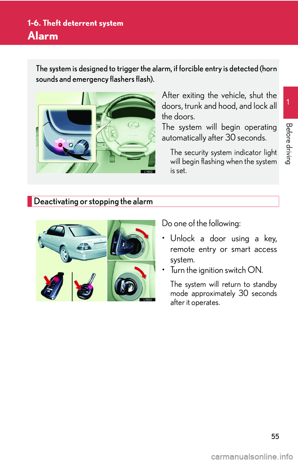
Deactivating or stopping the alarm
Do one of the following:
• Unlock a door using a key, r
emote entry or smart access
system.
• Turn the ignition switch ON.
The system will return to standby
mode approximately 30 seconds
after it operates.
The system is designed to trigger the alarm, if forcible entry is detected (horn
sounds and emergency flashers flash).
After exiting the vehicle, shut the
doors, trunk and hood, and lock all
the doors.
The system will begin operating
automatically af
ter 30 seconds.
The security system indicator light
will begin flashing when the system
is set.
Page 114 of 419
98
2-1. Driving procedures
Automatic transmission
Select a gear position appropriate for the driving conditions.
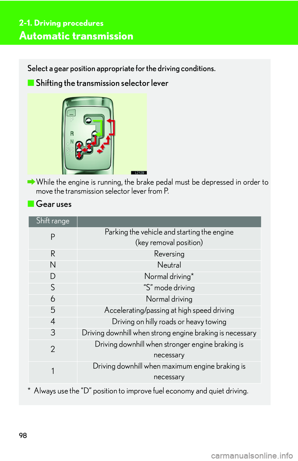
■Shifting the transmission selector lever
While the engine is running, the brake pedal must be depressed in order to
move the transmission selector lever from P.
■Gear uses
* Always use the “D” position to improve fuel economy and quiet driving.
Shift range
PParking the vehicle and starting the engine
(key removal position)
RReversing
NNeutral
DNormal driving*
S“S” mode driving
6Normal driving
5Accelerating/passing at high speed driving
4Driving on hilly roads or heavy towing
3Driving downhill when strong engine braking is necessary
2Driving downhill when stronger engine braking is necessary
1Driving downhill when maximum engine braking is
necessary
Page 145 of 419
129
2-4. Using other driving systems
2
When driving
Dynamic radar/ laser cruise control
The vehicle-to-vehicle distance control mode allows the vehicle to follow
another vehicle, adjusting to the leading vehicle’s speed variations, and the
conventional cruise control mode allows for driving at a preset speed, both
without the need to press the accelerator pedal.
■ Selecting a cruise control mode
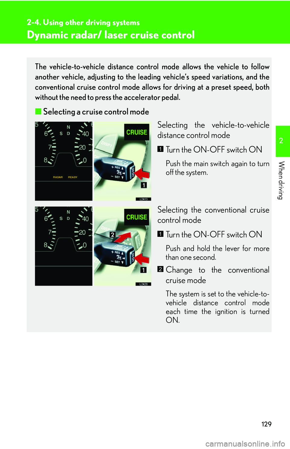
Selecting the vehicle-to-vehicle
distance contr
ol mode
Turn the ON-OFF switch ON
Push the main switch again to turn
off the system.
Selecting the conventional cruise
control mode Turn the ON-OFF switch ON
Push and hold the lever for more
than one second.
Change to the conventional
cruise mode
The system is set to the vehicle-to-
vehicle distance control mode
each time the ignition is turned
ON.
1
1
2
Page 187 of 419
171
3-1. Using the air conditioning system and defogger
3
Interior features
■Window defogger feature
The automatic air conditioning control system detects the operating conditions of
the s
ystem and automatically switches between recirculated and outside air modes.
■Outside rear view mirror heaters
Pressing the rear window defogger button also turns the mirror heaters on.
CAUTION
■When the defogger is on
Do not touch the rear view mirror surfaces, as the surfaces can become very hot
and burn y
ou.
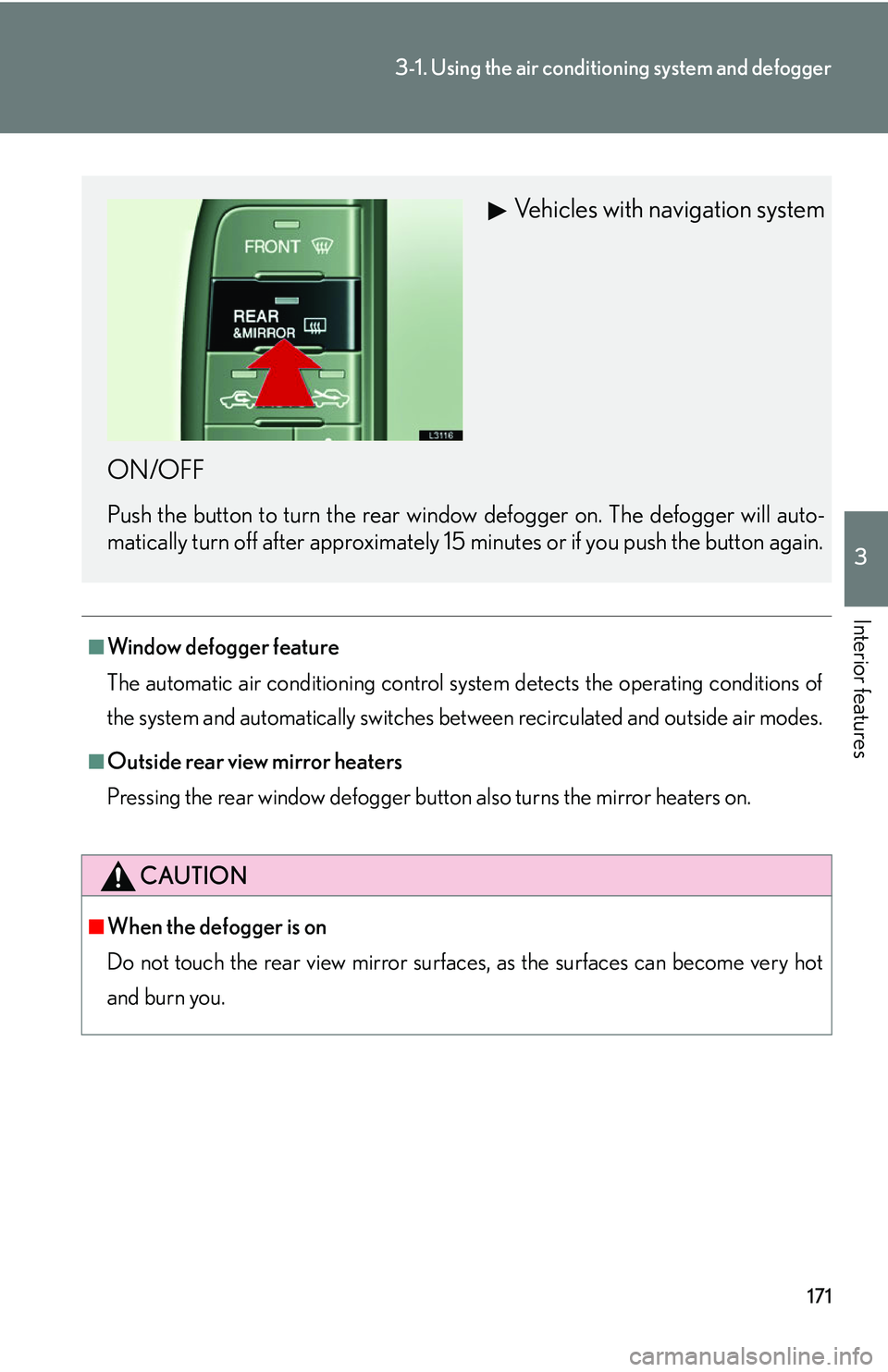
Vehicles with navigation system
ON/OFF
Push the button to turn the rear wind ow defogger on. The defogger will auto -
matically turn off after approximately 15 minutes or if you push the button again.
Page 189 of 419
173
3-1. Using the air conditioning system and defogger
3
Interior features
Adjusting the setting
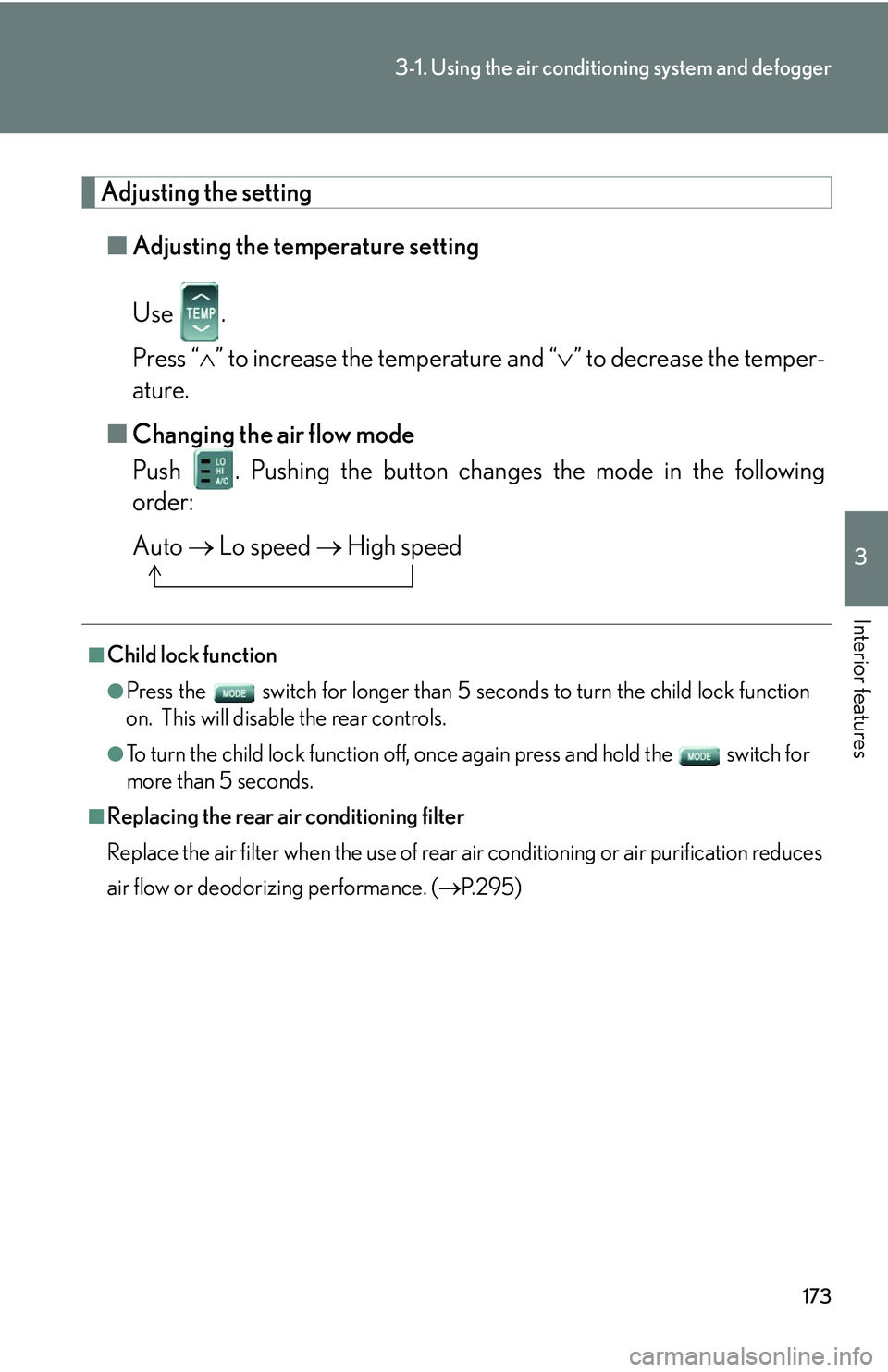
■Adjusting the temperature setting
Use .
Press “ ” to increase the temperature and “ ” to decrease the temper -
ature.
■ Changing the air flo
w mode
Push . Pushing the button changes the mode in the following
order:
Auto Lo speed High speed
■Child lock function
●Press the switch for longer than 5 seconds t o turn the child lock function
on. This will disable the rear controls.
●To turn the child lock function off, once again press and hold the switch for
more than 5 seconds.
■Replacing the rear air conditioning filter
Replace the air filter when the use of rear air conditioning or air purification reduces
air
flow or deodorizing performance. ( P. 2 9 5 )
Page 208 of 419
192
3-2. Using the audio system
Adjusting sound quality, volume, balance and sound level
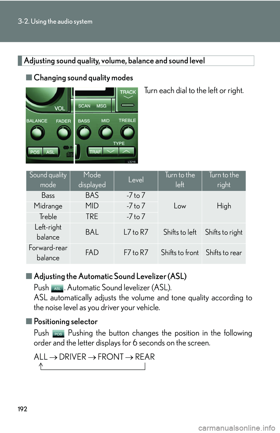
■Changing sound quality modes
Turn each dial to the left or right.
■ A
djusting the Automatic Sound Levelizer (ASL)
Push . Automatic Sound levelizer (ASL).
ASL automatically adjusts the volu me and tone quality accor
ding to
the noise level as you driver your vehicle.
■ P
ositioning selector
Push Pushing the button changes th e position in the follo
wing
order and the letter displays fo r 6 seconds on the scr
een.
ALL DRI
VER FRONT REAR
Sound quality
modeMode
displayedLevelTurn to the leftTurn to the right
BassBAS-7 t o 7
LowHighMidrangeMID-7 t o 7
Tr e b l eTRE-7 t o 7
Left-right balanceBALL7 to R7Shifts to leftShifts to right
Forward-rear
balanceFA DF7 to R7Shifts to frontShifts to rear
Page 209 of 419
193
3-2. Using the audio system
3
Interior features
Using the rear controller
Turning on the power and selecting audio modes
■Pow e r
Push when the audio system is turned OFF.
■ Cha
nging modes
Push when the audio system is turned ON. P
ushing the button
changes the sound mode in the fo llo
wing order: AM, FM, cassette
deck, (CD changer).
Adjusting the volume
Push .
Continual adjustment is possible if the button is held for more than one
second.
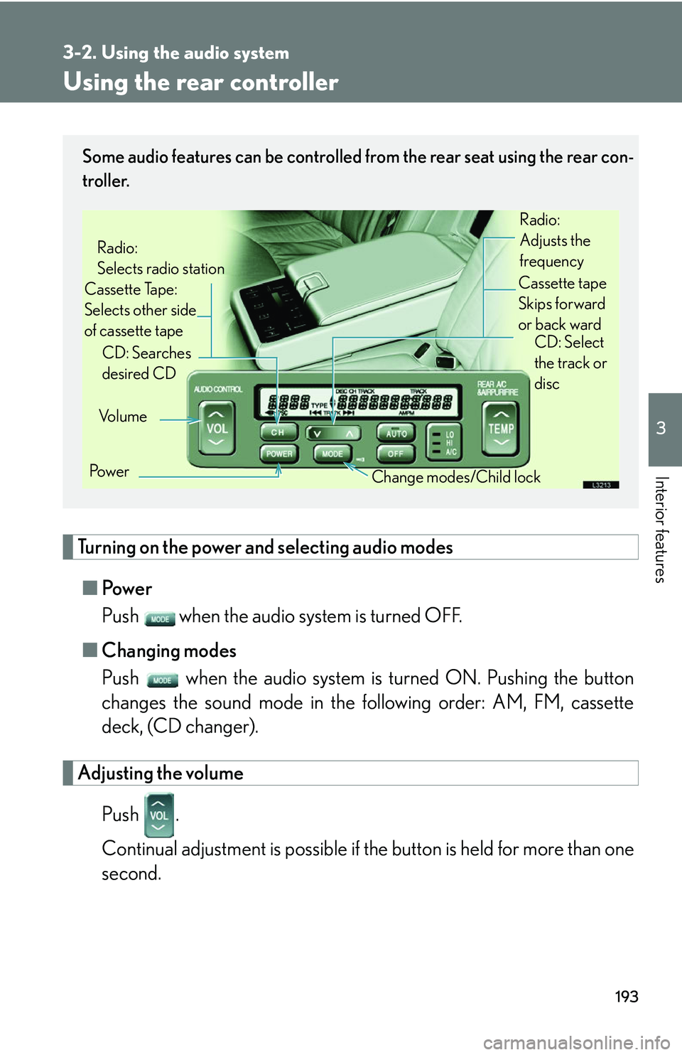
Some audio features can be controlled from the rear seat using the rear con-
troller.
Vo l u m e
Cassette Tape:
Selects other side
of cassette tape Radio:
Selects radio station
Po w e r Change modes/Child lock
CD: Searches
desired CD
Radio:
Adjusts the
frequency
Cassette tape
Skips forward
or back ward CD: Select
the track or
disc
Page 399 of 419
383
6-1. Specifications
6
Vehicle specifications
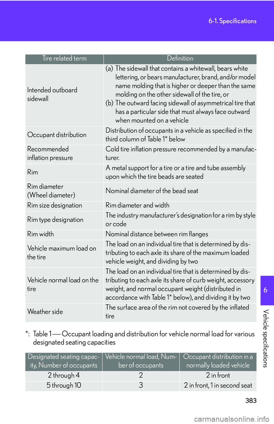
*: Table 1 Occupant loading and distribution for vehicle normal load for various
designated seating capacities
Tire related termDefinition
Intended outboard
sidewall
(a) The sidewall that contains a whitewall, bears white
lettering, or bears manufacturer, brand, and/or model
name molding that is higher or deeper than the same
molding on the other sidewall of the tire, or
(b) The outward facing sidewall of asymmetrical tire that
has a particular side that must always face outward
when mounted on a vehicle
Occupant distributionDistribution of occupants in a vehicle as specified in the
third column of Table 1* below
Recommended
inflation pressure
Cold tire inflation pressure recommended by a manufac -
turer.
RimA metal support for a tire or a tire and tube assembly
upon which the tire beads are seated
Rim diameter
(Wheel diameter)Nominal diameter of the bead seat
Rim size designationRim diameter and width
Rim type designationThe industry manufacturer’s designation for a rim by style
or code
Rim widthNominal distance between rim flanges
Vehicle maximum load on
the tireThe load on an individual tire that is determined by dis -
tributing to each axle its share of the maximum loaded
vehicle weight, and dividing by two
Vehicle normal load on the
tire
The load on an individual tire that is determined by dis-
tributing to each axle its share of curb weight, accessory
weight, and normal occupant weight (distributed in
accordance with Table 1* below), and dividing it by two
We a t h e r s i d eThe surface area of the rim not covered by the inflated
tire
Designated seating capac -
ity, Number of occupants
Vehicle normal load, Num -
ber of occupants
Occupant distribution in a
normally loaded vehicle
2 through 422 in front
5 through 1032 in front, 1 in second seat