set LEXUS LS500 2019 Owners Manual
[x] Cancel search | Manufacturer: LEXUS, Model Year: 2019, Model line: LS500, Model: LEXUS LS500 2019Pages: 512, PDF Size: 9.71 MB
Page 31 of 512
311-1. For safe use
LS500_OM_(U)_1810 1
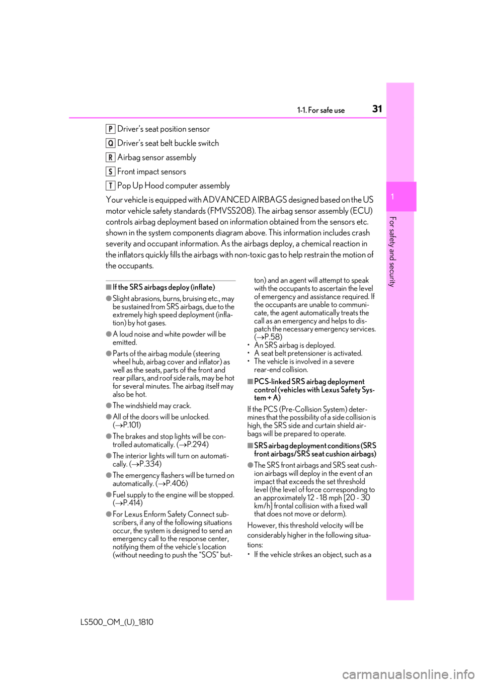
For safety and security Driver’s seat position sensor
Driver’s seat belt buckle switch
Airbag sensor assembly
Front impact sensors
Pop Up Hood computer assembly
Your vehicle is equipped with ADVANCED AIRBAGS designed based on the US
motor vehicle safety standards (FMVSS208). The airbag sensor assembly (ECU)
controls airbag deployment based on information obtained from the sensors etc.
shown in the system components diagram above. This information includes crash
severity and occupant information. As the airbags deploy, a chemical reaction in
the inflators quickly fills the airbags with no n-toxic gas to help restrain the motion of
the occupants. ■
If the SRS airbags deploy (inflate)●
Slight abrasions, burns, bruising etc., may
be sustained from SRS airbags, due to the
extremely high speed deployment (infla-
tion) by hot gases.●
A loud noise and white powder will be
emitted.●
Parts of the airbag module (steering
wheel hub, airbag cover and inflator) as
well as the seats, parts of the front and
rear pillars, and roof side rails, may be hot
for several minutes. The airbag itself may
also be hot.●
The windshield may crack.●
All of the doors will be unlocked.
( P.101)●
The brakes and stop lights will be con-
trolled automatically. ( P.294)
●
The interior lights will turn on automati-
cally. ( P.334)
●
The emergency flashers will be turned on
automatically. ( P.406)
●
Fuel supply to the engine will be stopped.
( P.414)
●
For Lexus Enform Safety Connect sub-
scribers, if any of the following situations
occur, the system is designed to send an
emergency call to the response center,
notifying them of the vehicle’s location
(without needing to push the “SOS” but- ton) and an agent will attempt to speak
with the occupants to ascertain the level
of emergency and assistance required. If
the occupants are unable to communi-
cate, the agent automatically treats the
call as an emergency and helps to dis-
patch the necessary emergency services.
( P.58)
• An SRS airbag is deployed.
• A seat belt pretensioner is activated.
• The vehicle is involved in a severe
rear-end collision. ■
PCS-linked SRS airbag deployment
control (vehicles with Lexus Safety Sys-
tem + A)
If the PCS (Pre-Collision System) deter-
mines that the possibility of a side collision is
high, the SRS side and curtain shield air-
bags will be prepared to operate.
■
SRS airbag deployment conditions (SRS
front airbags/SRS seat cushion airbags)
●
The SRS front airbags and SRS seat cush-
ion airbags will deploy in the event of an
impact that exceed s the set threshold
level (the level of fo rce corresponding to
an approximately 12 - 18 mph [20 - 30
km/h] frontal collision with a fixed wall
that does not move or deform).
However, this threshol d velocity will be
considerably higher in the following situa-
tions:
• If the vehicle strikes an object, such as a P
Q
R
S
T
Page 32 of 512
32 1-1. For safe use
LS500_OM_(U)_1810 parked vehicle or sign pole, which can
move or deform on impact
• If the vehicle is involved in an underride
collision, such as a collision in which the
front of the vehicle underrides, or goes
under, the bed of a truck●
Depending on th e type of collision, it is
possible that only the seat belt preten-
sioners will activate.●
The SRS front airbags for the front pas-
senger will not activate if there is no pas-
senger sitting in the front passenger seat.
However, the SRS fr ont airbags for the
front passenger may deploy if luggage is
put in the seat, even if the seat is unoccu-
pied.●
The SRS seat cushion airbags on the rear
seat will not operate if the occupant is not
wearing a seat belt.■
SRS airbag deployment conditions (SRS
side and curtain shield airbags)●
The SRS side and curtain shield airbags
will deploy in the even t of an impact that
exceeds the set thresh old level (the level
of force corresponding to the impact
force produced by an approximately
3300 lb. [1500 kg] vehicle colliding with
the vehicle cabin from a direction per-
pendicular to the vehi cle orientation at an
approximate speed of 12 - 18 mph [20 -
30 km/h]).●
Both SRS curtain shield airbags may
deploy in the event of a severe side colli-
sion.●
Both SRS curtain shield airbags will
deploy in the event of vehicle rollover.●
Both SRS curtain shield airbags may also
deploy in the event of a severe frontal col-
lision.
■
Conditions under which the SRS air-
bags may deploy (inf late), other than a
collision
The SRS front airbags, SRS curtain shield
airbags and SRS seat cushion airbags may
also deploy if a serious impact occurs to the
underside of your vehicle. Some examples
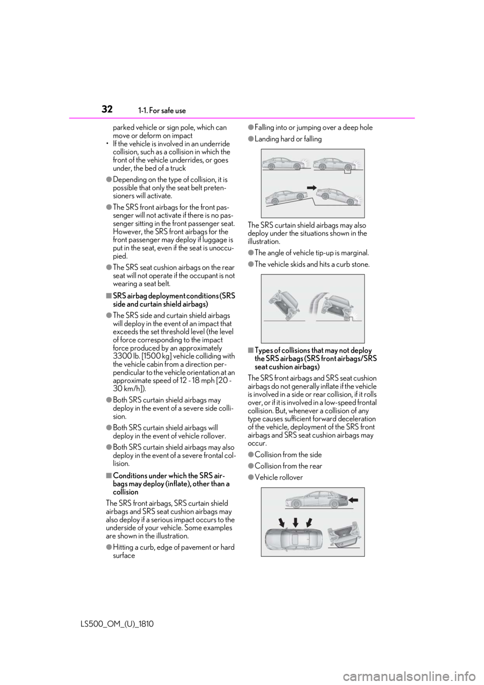
are shown in the illustration.
●
Hitting a curb, edge of pavement or hard
surface ●
Falling into or jumping over a deep hole ●
Landing hard or falling
The SRS curtain shield airbags may also
deploy under the situations shown in the
illustration. ●
The angle of vehicle tip-up is marginal. ●
The vehicle skids and hits a curb stone.
■
Types of collisions that may not deploy
the SRS airbags (SRS front airbags/SRS
seat cushion airbags)
The SRS front airbags and SRS seat cushion
airbags do not generally inflate if the vehicle
is involved in a side or rear collision, if it rolls
over, or if it is involv ed in a low-speed frontal
collision. But, whenever a collision of any
type causes sufficient forward deceleration
of the vehicle, deploy ment of the SRS front
airbags and SRS seat cushion airbags may
occur. ●
Collision from the side
●
Collision from the rear
●
Vehicle rollover
Page 62 of 512

62 1-3. Lexus Enform
LS500_OM_(U)_1810 Lexus.com.
Important! Read this information about
exposure to radio frequency signals
before using Safety Connect;
The Safety Connect system installed in
your vehicle is a low-power radio trans-
mitter and receiver. It receives and also
sends out radio frequency (RF) signals.
In August 1996, the Federal Commu-
nications Commission (FCC) adopted
RF exposure guidelines with safety lev-
els for mobile wireless phones. Those
guidelines are consistent with the
safety standards previously set by the
following U.S. and international stan-
dards bodies.
ANSI (American National Stan-
dards Institute) C95.1 [1992]
NCRP (National Council on Radia-
tion Protection and Measurement)
Report 86 [1986]
ICNIRP (International Commission
on Non-Ionizing Radiation Protec-
tion) [1996]
Those standards were based on com-
prehensive and periodic evaluations of
the relevant scientific literature. Over
120 scientists, engi neers, and physi-
cians from universi ties, and govern-
ment health agencies and industries
reviewed the available body of
research to develop the ANSI Stan-
dard (C95.1).
The design of Safety Connect com- plies with the FCC guidelines in addi-
tion to those standards.
Safety information for Safety
Connect
Page 65 of 512
651-4. Theft deterrent system
LS500_OM_(U)_1810 1
For safety and security
■
Items to check before locking the
vehicle
To prevent unexpected triggering of
the alarm and vehicle theft, make sure
of the following:
Nobody is in the vehicle.
The windows, moon roof (if
equipped) and panoramic moon
roof (if equipped) are closed before
the alarm is set.
No valuables or other personal
items are left in the vehicle. ■
Setting
Close the doors, trunk and hood, and
lock all the doors. The system will be
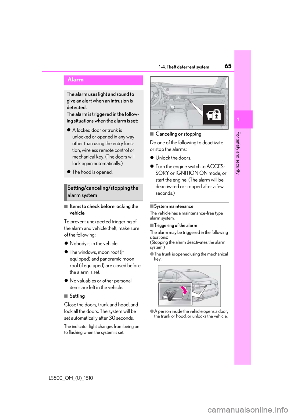
set automatically after 30 seconds. The indicator light changes from being on
to flashing when the system is set. ■
Canceling or stopping
Do one of the following to deactivate
or stop the alarms:
Unlock the doors.
Turn the engine switch to ACCES-
SORY or IGNITION ON mode, or
start the engine. (The alarm will be
deactivated or stopped after a few
seconds.) ■
System maintenance
The vehicle has a maintenance-free type
alarm system. ■
Triggering of the alarm
The alarm may be triggered in the following
situations:
(Stopping the alarm deactivates the alarm
system.) ●
The trunk is opened using the mechanical
key.
●
A person inside the vehicle opens a door,
the trunk or hood, or unlocks the vehicle.Alarm The alarm uses light and sound to
give an alert when an intrusion is
detected.
The alarm is triggered in the follow-
ing situations when the alarm is set:
A locked door or trunk is
unlocked or opened in any way
other than using the entry func-
tion, wireless remote control or
mechanical key. (The doors will
lock again automatically.)
The hood is opened.
Setting/canceling/stopping the
alarm system
Page 70 of 512
70 2-1. Instrument cluster
LS500_OM_(U)_1810 *1
: These lights come on when the engine
switch is turned to IGNITION ON
mode to indicate that a system check is
being performed. They will turn off after
the engine is started, or after a few sec-
onds. There may be a malfunction in a
system if the lights do not come on, or
turn off. Have the vehicle inspected by
your Lexus dealer. *2
: This light illuminates on the multi-infor-
mation display. *3
: This light illuminates on the center
panel. *4
: F SPORT models: This light comes on
when the engine switch is turned to
IGNITION ON mode to indicate that a
system check is being performed. They
will turn off after the engine is started, or
after a few seconds. There may be a
malfunction in a system if the lights do
not come on, or turn off. Have the vehi-
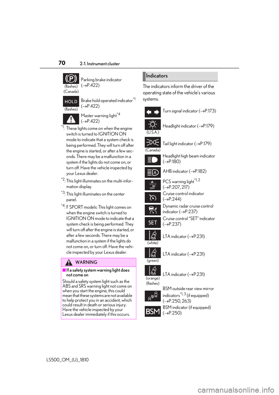
cle inspected by your Lexus dealer. The indicators inform the driver of the
operating state of the vehicle’s various
systems.(flashes)
(Canada)
Parking brake indicator
( P.422)(flashes)
Brake hold operated indicator *1
( P.422)
Master warning light *4
( P.422)
WARNING
■
If a safety system warning light does
not come on
Should a safety system light such as the
ABS and SRS warning light not come on
when you start the engine, this could
mean that these systems are not available
to help protect you in an accident, which
could result in death or serious injury.
Have the vehicle inspected by your
Lexus dealer immediately if this occurs. Indicators Turn signal indicator ( P.173)(U.S.A.)
Headlight indicator ( P.179)(Canada)
Tail light indicator ( P.179)
Headlight high beam indicator
( P.180)
AHB indicator ( P.182)
PCS warning light *1, 2
( P.207, 217)
Cruise control indicator
( P.244)
Dynamic radar cruise control
indicator ( P.237)
Cruise control “SET” indicator
( P.237)
(white)
LTA indicator ( P.231)
(green)
LTA indicator ( P.231)
(orange)
(flashes)
LTA indicator ( P.231)
BSM outside rear view mirror
indicators *1, 3
(if equipped)
( P.250, 263)
BSM indicator (if equipped)
( P.250)
Page 74 of 512
74 2-1. Instrument cluster
LS500_OM_(U)_1810 Displays warning messages if a malfunction occurs ( P.425)■
Outside temperature display●
In the following situations, the correct
outside temperature may not be dis-
played, or the display may take longer
than normal to change:
• When stopped, or driving at low speeds
(less than 12 mph [20 km/h])
• When the outside temperature has
changed suddenly (at the entrance/exit of
a garage, tunnel, etc.)●
When “--” or “E” is displayed, the system
may be malfunctioning. Take your vehicle
to your Lexus dealer.■
Liquid crystal display
P.81■
Customization
The gauges and meters can be customized
on of the multi-information display.
( P.85) ■
Display items
Odometer Displays the total distance the vehicle has
been driven.
Trip meter A/trip meter B Displays the distance the vehicle has been
driven since the meter was last reset. Trip
meters A and B can be used to record and
display different distances independently.
Distance until next engine oil
change Displays the distance the vehicle can be
driven until an oil change is necessary. ■
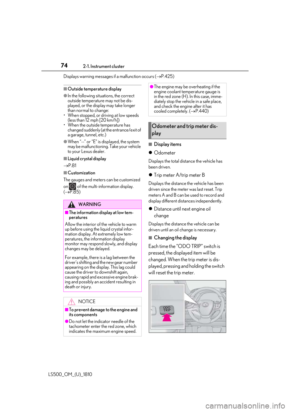
Changing the display
Each time the “ODO TRIP” switch is
pressed, the displayed item will be
changed. When the trip meter is dis-
played, pressing and holding the switch
will reset the trip meter.WARNING■
The information display at low tem-
peratures
Allow the interior of the vehicle to warm
up before using the liquid crystal infor-
mation display. At extremely low tem-
peratures, the in formation display
monitor may respond slowly, and display
changes may be delayed.
For example, there is a lag between the
driver’s shifting and the new gear number
appearing on the display. This lag could
cause the driver to downshift again,
causing rapid and excessive engine brak-
ing and possibly an accident resulting in
death or injury.
NOTICE
■
To prevent damage to the engine and
its components
●
Do not let the indicator needle of the
tachometer enter the red zone, which
indicates the maximum engine speed. ●
The engine may be overheating if the
engine coolant temperature gauge is
in the red zone (H). In this case, imme-
diately stop the vehicle in a safe place,
and check the engine after it has
cooled completely. ( P.440)
Odometer and trip meter dis-
play
Page 78 of 512
78 2-1. Instrument cluster
LS500_OM_(U)_1810 Engine coolant temperature gaugeDisplays the engine coolant temperature
Multi-information displayPresents the driver with a variety of vehicle data ( P.80)
Displays warning messages if a malfunction occurs ( P.425)■
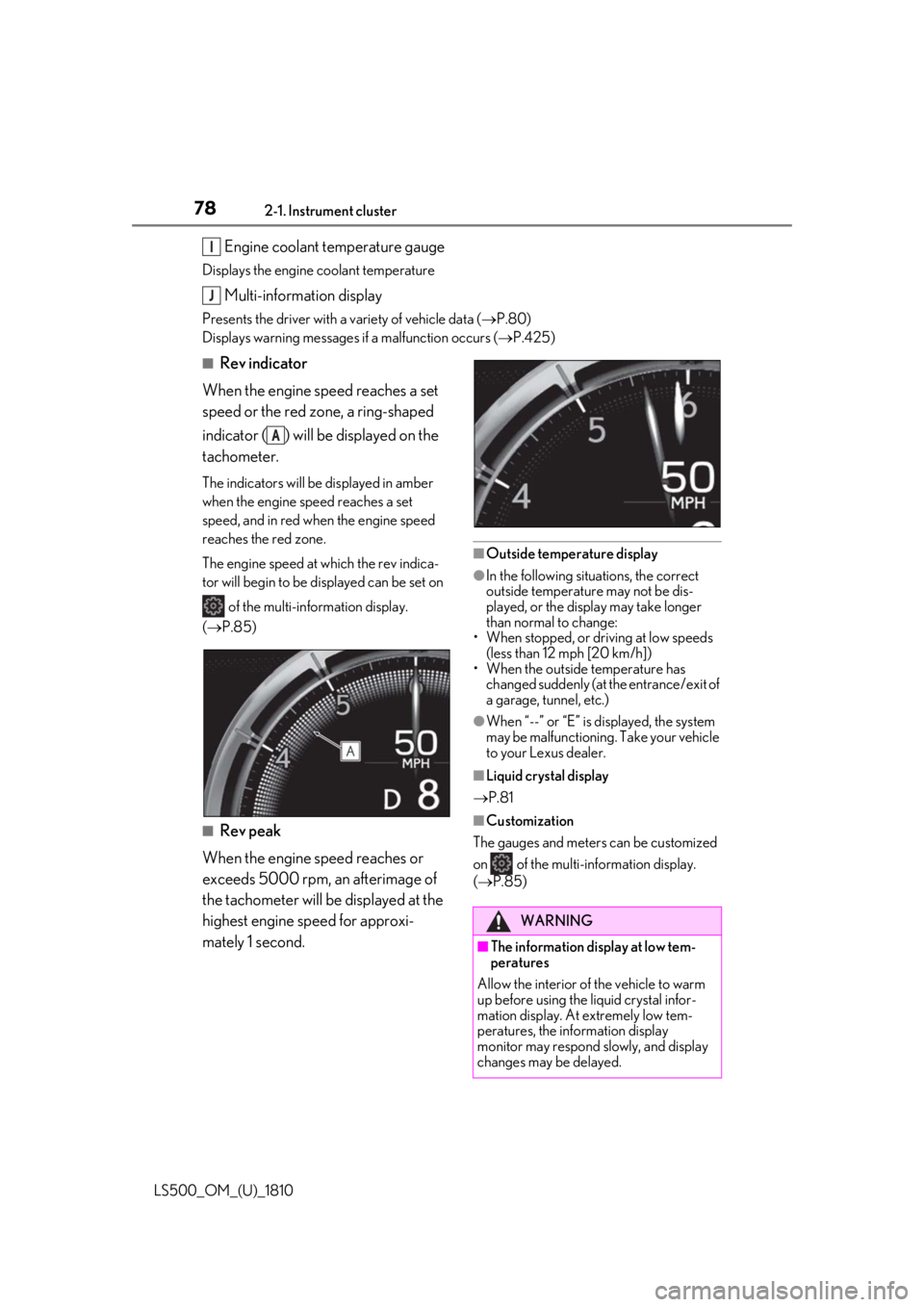
Rev indicator
When the engine speed reaches a set
speed or the red zone, a ring-shaped
indicator ( ) will be displayed on the
tachometer. The indicators will be displayed in amber
when the engine speed reaches a set
speed, and in red when the engine speed
reaches the red zone.
The engine speed at which the rev indica-
tor will begin to be displayed can be set on
of the multi-information display.
( P.85)
■
Rev peak
When the engine speed reaches or
exceeds 5000 rpm, an afterimage of
the tachometer will be displayed at the
highest engine speed for approxi-
mately 1 second. ■
Outside temperature display ●
In the following situations, the correct
outside temperature may not be dis-
played, or the display may take longer
than normal to change:
• When stopped, or driving at low speeds
(less than 12 mph [20 km/h])
• When the outside temperature has
changed suddenly (at the entrance/exit of
a garage, tunnel, etc.) ●
When “--” or “E” is displayed, the system
may be malfunctioning. Take your vehicle
to your Lexus dealer. ■
Liquid crystal display
P.81 ■
Customization
The gauges and meters can be customized
on of the multi-information display.
( P.85)I
J
A
WARNING
■
The information display at low tem-
peratures
Allow the interior of the vehicle to warm
up before using the liquid crystal infor-
mation display. At extremely low tem-
peratures, the information display
monitor may respond slowly, and display
changes may be delayed.
Page 79 of 512
792-1. Instrument cluster
LS500_OM_(U)_1810 2
Vehicle status information and indicators
■
Display items
Odometer Displays the total distance the vehicle has
been driven.
Trip meter A/trip meter B Displays the distance the vehicle has been
driven since the meter was last reset. Trip
meters A and B can be used to record and
display different distances independently.
Distance until next engine oil
change Displays the distance the vehicle can be
driven until an oil change is necessary.
■
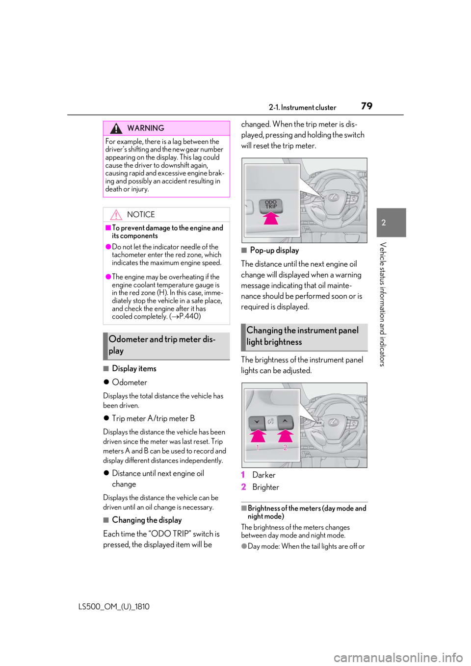
Changing the display
Each time the “ODO TRIP” switch is
pressed, the displayed item will be changed. When the trip meter is dis-
played, pressing and holding the switch
will reset the trip meter.
■
Pop-up display
The distance until the next engine oil
change will displayed when a warning
message indicating that oil mainte-
nance should be performed soon or is
required is displayed.
The brightness of the instrument panel
lights can be adjusted.
1 Darker
2 Brighter ■
Brightness of the meters (day mode and
night mode)
The brightness of the meters changes
between day mode and night mode.
●
Day mode: When the tail lights are off or WARNING
For example, there is a lag between the
driver’s shifting and the new gear number
appearing on the display. This lag could
cause the driver to downshift again,
causing rapid and excessive engine brak-
ing and possibly an accident resulting in
death or injury.
NOTICE■
To prevent damage to the engine and
its components●
Do not let the indicator needle of the
tachometer enter the red zone, which
indicates the maximum engine speed.●
The engine may be overheating if the
engine coolant temperature gauge is
in the red zone (H). In this case, imme-
diately stop the vehicle in a safe place,
and check the engine after it has
cooled completely. ( P.440)
Odometer and trip meter dis-
play Changing the instrument panel
light brightness
Page 80 of 512
80 2-1. Instrument cluster
LS500_OM_(U)_1810 when the tail lights are on but the sur-
rounding area is bright●
Night mode: When the tail lights are on
and the surrounding area is dark
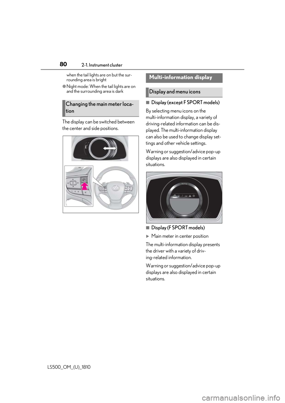
The display can be switched between
the center and side positions. ■
Display (except F SPORT models)
By selecting menu icons on the
multi-information display, a variety of
driving-related information can be dis-
played. The multi-information display
can also be used to change display set-
tings and other vehicle settings.
Warning or suggestion/advice pop-up
displays are also displayed in certain
situations.
■
Display (F SPORT models)
Main meter in center position
The multi-informatio n display presents
the driver with a variety of driv-
ing-related information.
Warning or suggestion/advice pop-up
displays are also displayed in certain
situations.Changing the main meter loca-
tion Multi-information display
Display and menu icons
Page 81 of 512
812-1. Instrument cluster
LS500_OM_(U)_1810 2
Vehicle status information and indicators
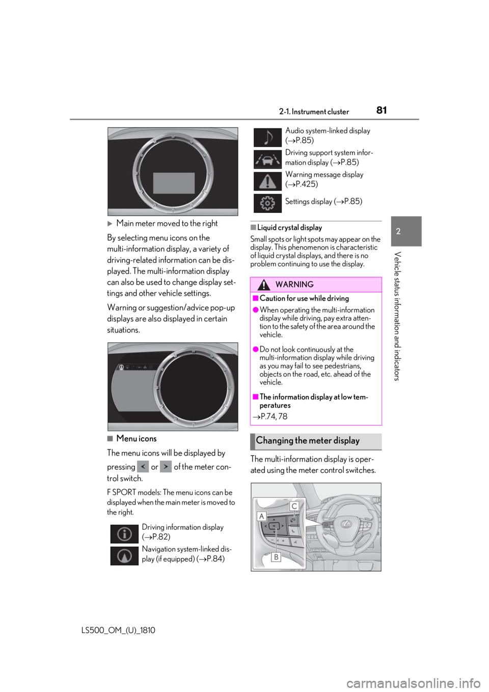
Main meter moved to the right
By selecting menu icons on the
multi-information display, a variety of
driving-related information can be dis-
played. The multi-information display
can also be used to change display set-
tings and other vehicle settings.
Warning or suggestion/advice pop-up
displays are also displayed in certain
situations.
■
Menu icons
The menu icons will be displayed by
pressing or of the meter con-
trol switch. F SPORT models: The menu icons can be
displayed when the main meter is moved to
the right. ■
Liquid crystal display
Small spots or light sp ots may appear on the
display. This phenomen on is characteristic
of liquid crystal disp lays, and there is no
problem continuing to use the display.
The multi-information display is oper-
ated using the meter control switches.
Driving information display
( P.82)
Navigation syst em-linked dis-
play (if equipped) ( P.84) Audio system-linked display
( P.85)
Driving support system infor-
mation display ( P.85)
Warning message display
( P.425)
Settings display ( P.85)
WARNING■
Caution for use while driving ●
When operating the multi-information
display while drivin g, pay extra atten-
tion to the safety of the area around the
vehicle. ●
Do not look continuously at the
multi-information display while driving
as you may fail to see pedestrians,
objects on the road, etc. ahead of the
vehicle. ■
The information display at low tem-
peratures
P.74, 78
Changing the meter display