power LEXUS RX350 2011 Workshop Manual
[x] Cancel search | Manufacturer: LEXUS, Model Year: 2011, Model line: RX350, Model: LEXUS RX350 2011Pages: 821, PDF Size: 13.27 MB
Page 485 of 821
415
3-7. Other interior features
3
Interior features
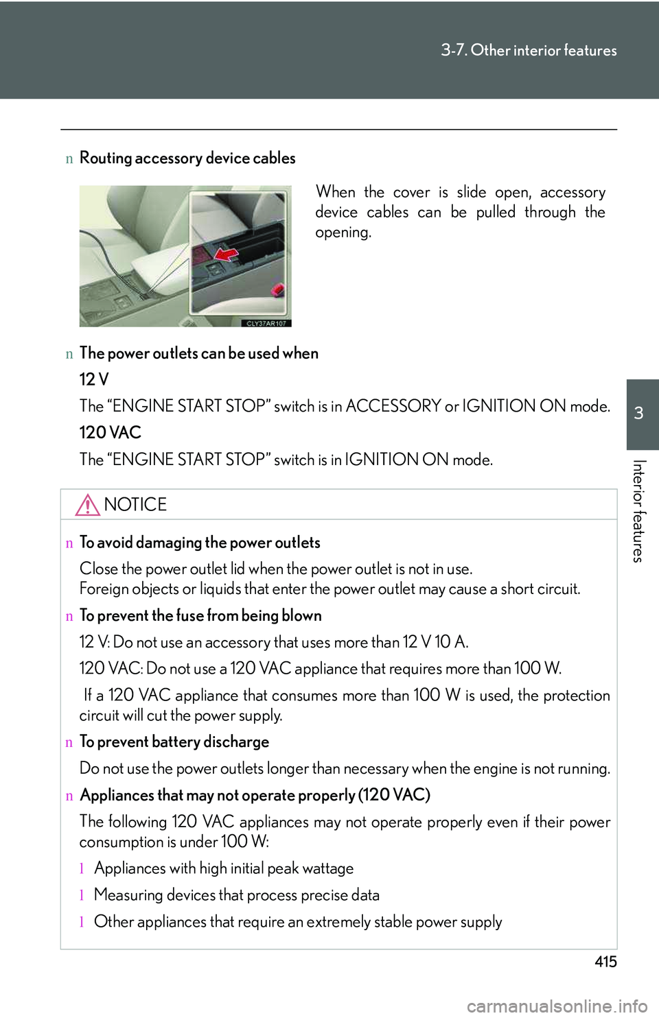
nRouting accessory device cables
nThe power outlets can be used when
12 V
The “ENGINE START STOP” switch is in ACCESSORY or IGNITION ON mode.
120 VAC
The “ENGINE START STOP” switch is in IGNITION ON mode.
NOTICE
nTo avoid damaging the power outlets
Close the power outlet lid when the power outlet is not in use.
Foreign objects or liquids that enter the power outlet may cause a short circuit.
nTo prevent the fuse from being blown
12 V: Do not use an accessory that uses more than 12 V 10 A.
120 VAC: Do not use a 120 VAC appliance that requires more than 100 W.
If a 120 VAC appliance that consumes more than 100 W is used, the protection
circuit will cut the power supply.
nTo prevent battery discharge
Do not use the power outlets longer than necessary when the engine is not running.
nAppliances that may not operate properly (120 VAC)
The following 120 VAC appliances may not operate properly even if their power
consumption is under 100 W:
lAppliances with high initial peak wattage
lMeasuring devices that process precise data
lOther appliances that require an extremely stable power supply
When the cover is slide open, accessory
device cables can be pulled through the
opening.
Page 505 of 821
435
3-7. Other interior features
3
Interior features
nConditions unfavorable to correct operation
The compass may not show the correct direction in the following conditions:
lThe vehicle is stopped immediately after turning.
lThe vehicle is on an inclined surface.
lThe vehicle is in a place where the earth's magnetic field is subject to interfer-
ence by artificial magnetic fields (underground car park/parking lot, under a
steel tower, between buildings, roof car park/parking lot, near an intersection,
near a large vehicle, etc.).
lThe vehicle has become magnetized. (There is a magnet or metal object near
the inside rear view mirror.)
lThe battery has been disconnected.
lA door is open.
CAUTION
nWhile driving the vehicle
Do not adjust the display. Adjust the display only when the vehicle is stopped.
nWhen doing the circling calibration
Secure a wide space, and watch out for people and vehicles in the vicinity. Do not
violate any local traffic rules while performing circling calibration.
NOTICE
nTo avoid compass malfunctions
Do not place magnets or any metal objects near the inside rear view mirror.
Doing this may cause the compass sensor malfunction.
nTo ensure normal operation of the compass
lDo not perform a circling calibration of the compass in a place where the earth's
magnetic field is subject to interference by artificial magnetic fields.
lDuring calibration, do not operate electric systems (moon roof, power windows,
etc.) as they may interfere with the calibration.
Page 511 of 821
441
3-7. Other interior features
3
Interior features
Safety information for Safety Connect
Important! Read this information before using Safety Connect.
nExposure to radio frequency signals
The Safety Connect system installed in your vehicle is a low-power
radio transmitter and receiver. It receives and also sends out radio fre-
quency (RF) signals.
In August 1996, the Federal Communications Commission (FCC)
adopted RF exposure guidelines with safety levels for mobile wireless
phones. Those guidelines are consistent with the safety standards pre-
viously set by the following U.S. and international standards bodies.
lANSI (American National Standards Institute) C95.1 [1992]
lNCRP (National Council on Radiation Protection and Measure-
ment) Report 86 [1986]
lICNIRP (International Commission on Non-Ionizing Radiation Pro-
tection) [1996]
Those standards were based on comprehensive and periodic evalua-
tions of the relevant scientific literature. Over 120 scientists, engineers,
and physicians from universities, and government health agencies and
industries reviewed the available body of research to develop the
ANSI Standard (C95.1).
The design of Safety Connect complies with the FCC guidelines in
addition to those standards.
Page 544 of 821
474
4-3. Do-it-yourself maintenance
Battery
Check the battery as follows.
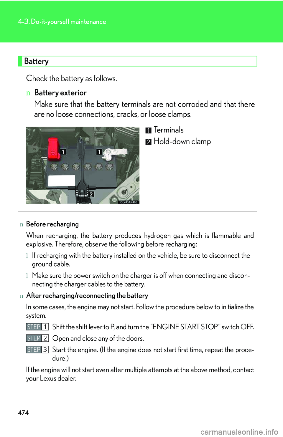
nBattery exterior
Make sure that the battery terminals are not corroded and that there
are no loose connections, cracks, or loose clamps.
Terminals
Hold-down clamp
nBefore recharging
When recharging, the battery produces hydrogen gas which is flammable and
explosive. Therefore, observe the following before recharging:
lIf recharging with the battery installed on the vehicle, be sure to disconnect the
ground cable.
lMake sure the power switch on the charger is off when connecting and discon-
necting the charger cables to the battery.
nAfter recharging/reconnecting the battery
In some cases, the engine may not start. Follow the procedure below to initialize the
system.
Shift the shift lever to P, and turn the “ENGINE START STOP” switch OFF.
Open and close any of the doors.
Start the engine. (If the engine does not start first time, repeat the proce-
dure.)
If the engine will not start even after multiple attempts at the above method, contact
your Lexus dealer.
STEP1
STEP2
STEP3
Page 571 of 821
501
4-3. Do-it-yourself maintenance
4
Maintenance and care
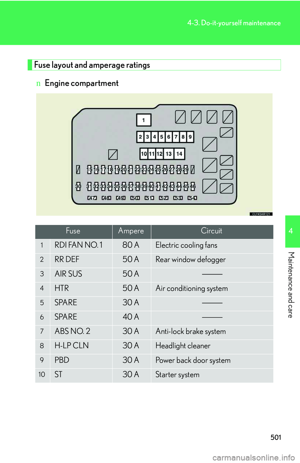
Fuse layout and amperage ratings
nEngine compartment
FuseAmpereCircuit
1RDI FAN NO. 180 AElectric cooling fans
2RR DEF50 ARear window defogger
3AIR SUS50 A
4HTR50 AAir conditioning system
5SPARE30 A
6SPARE40 A
7ABS NO. 230 AAnti-lock brake system
8H-LP CLN30 AHeadlight cleaner
9PBD30 APower back door system
10ST30 AStarter system
Page 572 of 821
502
4-3. Do-it-yourself maintenance
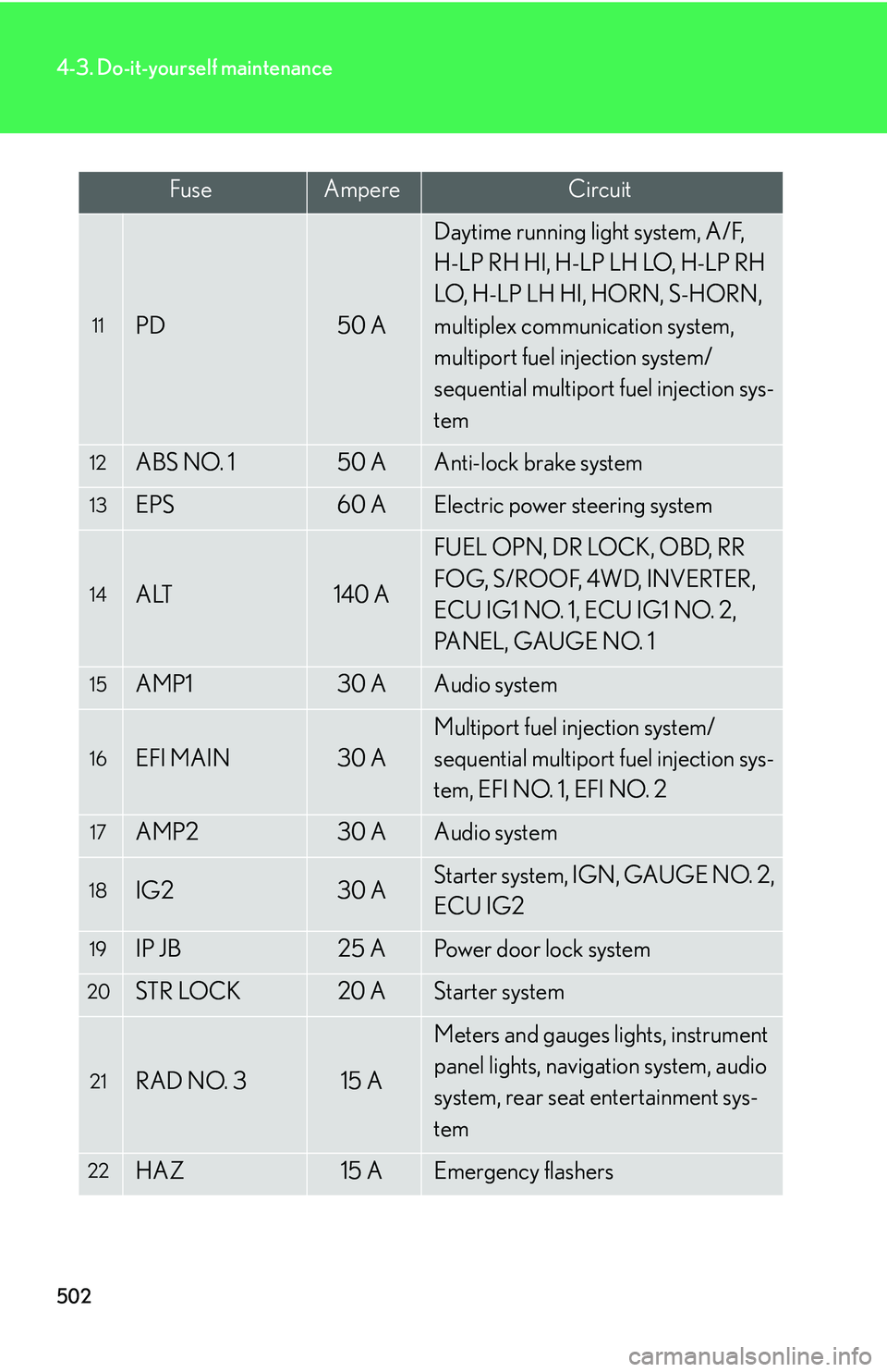
11PD50 A
Daytime running light system, A/F,
H-LP RH HI, H-LP LH LO, H-LP RH
LO, H-LP LH HI, HORN, S-HORN,
multiplex communication system,
multiport fuel injection system/
sequential multiport fuel injection sys-
tem
12ABS NO. 150 AAnti-lock brake system
13EPS60 AElectric power steering system
14ALT140 A
FUEL OPN, DR LOCK, OBD, RR
FOG, S/ROOF, 4WD, INVERTER,
ECU IG1 NO. 1, ECU IG1 NO. 2,
PANEL, GAUGE NO. 1
15AMP130 AAudio system
16EFI MAIN30 A
Multiport fuel injection system/
sequential multiport fuel injection sys-
tem, EFI NO. 1, EFI NO. 2
17AMP230 AAudio system
18IG230 AStarter system, IGN, GAUGE NO. 2,
ECU IG2
19IP JB25 APower door lock system
20STR LOCK20 AStarter system
21RAD NO. 315 A
Meters and gauges lights, instrument
panel lights, navigation system, audio
system, rear seat entertainment sys-
tem
22HAZ15 AEmergency flashers
FuseAmpereCircuit
Page 573 of 821
503
4-3. Do-it-yourself maintenance
4
Maintenance and care
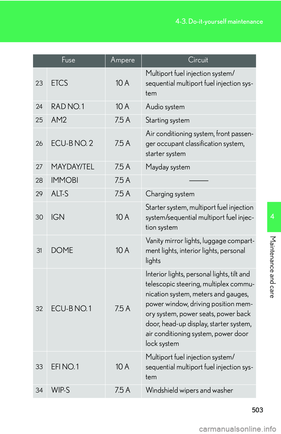
23ETCS10 A
Multiport fuel injection system/
sequential multiport fuel injection sys-
tem
24RAD NO. 110 AAudio system
25AM27. 5 AStarting system
26ECU-B NO. 27. 5 A
Air conditioning system, front passen-
ger occupant classification system,
starter system
27MAYDAY/TEL7. 5 AMayday system
28IMMOBI7. 5 A
29ALT-S7. 5 ACharging system
30IGN10 A
Starter system, multiport fuel injection
system/sequential multiport fuel injec-
tion system
31DOME10 A
Vanity mirror lights, luggage compart-
ment lights, interior lights, personal
lights
32ECU-B NO. 17. 5 A
Interior lights, personal lights, tilt and
telescopic steering, multiplex commu-
nication system, meters and gauges,
power window, driving position mem-
ory system, power seats, power back
door, head-up display, starter system,
air conditioning system, power door
lock system
33EFI NO. 110 A
Multiport fuel injection system/
sequential multiport fuel injection sys-
tem
34WIP-S7. 5 AWindshield wipers and washer
FuseAmpereCircuit
Page 575 of 821
505
4-3. Do-it-yourself maintenance
4
Maintenance and care
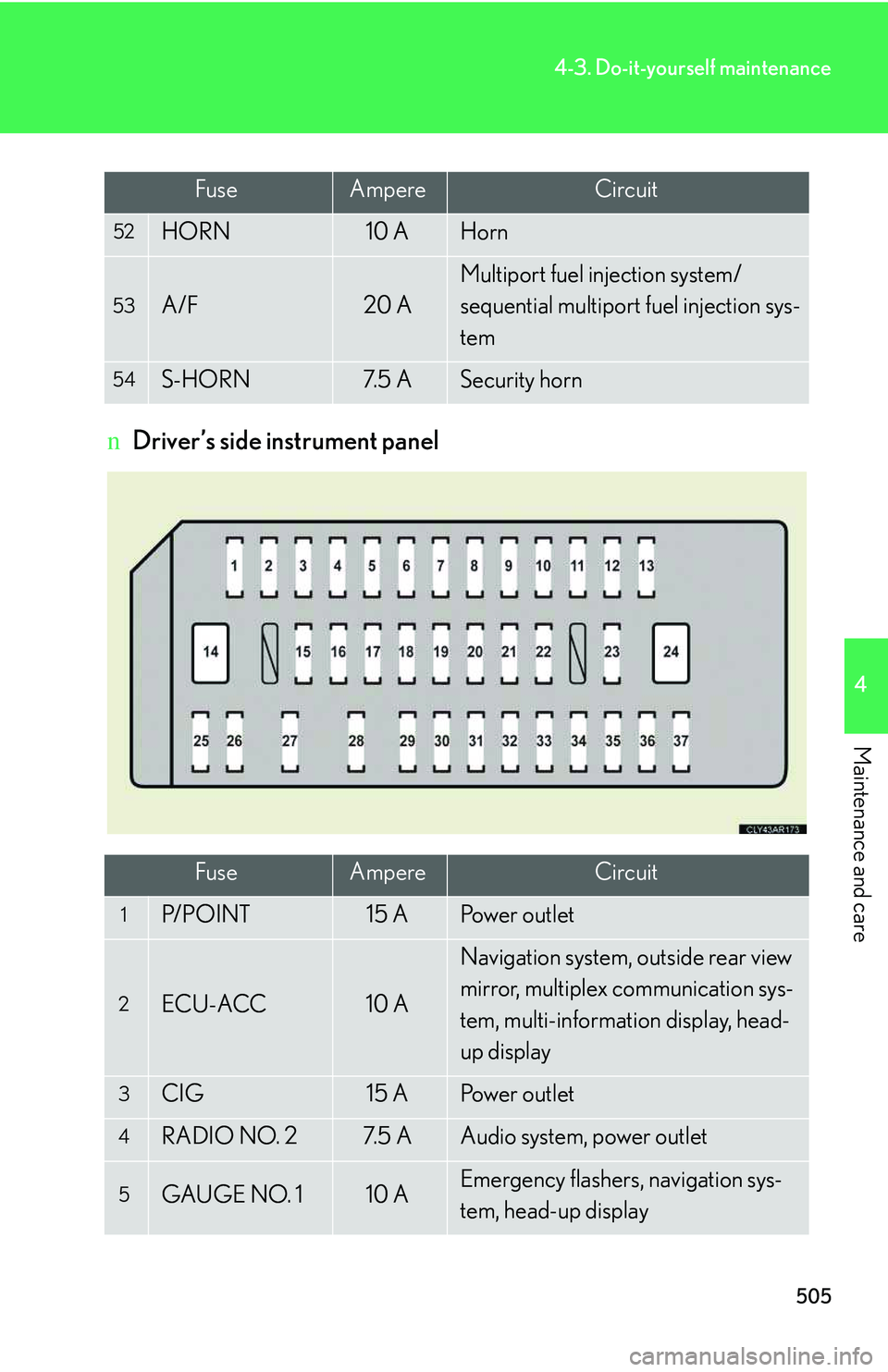
nDriver’s side instrument panel
52HORN10 AHorn
53A/F20 A
Multiport fuel injection system/
sequential multiport fuel injection sys-
tem
54S-HORN7. 5 ASecurity horn
FuseAmpereCircuit
1P/ P O I N T15 APo w e r o u t l e t
2ECU-ACC10 A
Navigation system, outside rear view
mirror, multiplex communication sys-
tem, multi-information display, head-
up display
3CIG15 APo w e r o u t l e t
4RADIO NO. 27. 5 AAudio system, power outlet
5GAUGE NO. 110 AEmergency flashers, navigation sys-
tem, head-up display
FuseAmpereCircuit
Page 576 of 821
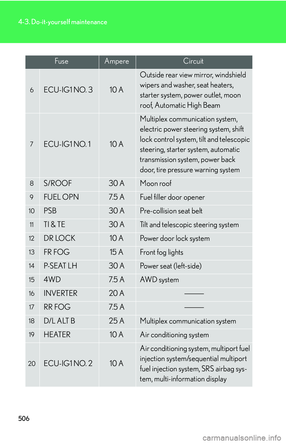
506
4-3. Do-it-yourself maintenance
6ECU-IG1 NO. 310 A
Outside rear view mirror, windshield
wipers and washer, seat heaters,
starter system, power outlet, moon
roof, Automatic High Beam
7ECU-IG1 NO. 110 A
Multiplex communication system,
electric power steering system, shift
lock control system, tilt and telescopic
steering, starter system, automatic
transmission system, power back
door, tire pressure warning system
8S/ROOF30 AMoon roof
9FUEL OPN7. 5 AFuel filler door opener
10PSB30 APre-collision seat belt
11TI & TE30 ATilt and telescopic steering system
12DR LOCK10 APower door lock system
13FR FOG15 AFront fog lights
14P-S E AT L H30 APo w e r s e a t ( l e f t - s i d e )
154WD7. 5 AAW D s y s t e m
16INVERTER20 A
17RR FOG7. 5 A
18D/L ALT B25 AMultiplex communication system
19HEATER10 AAir conditioning system
20ECU-IG1 NO. 210 A
Air conditioning system, multiport fuel
injection system/sequential multiport
fuel injection system, SRS airbag sys-
tem, multi-information display
FuseAmpereCircuit
Page 577 of 821
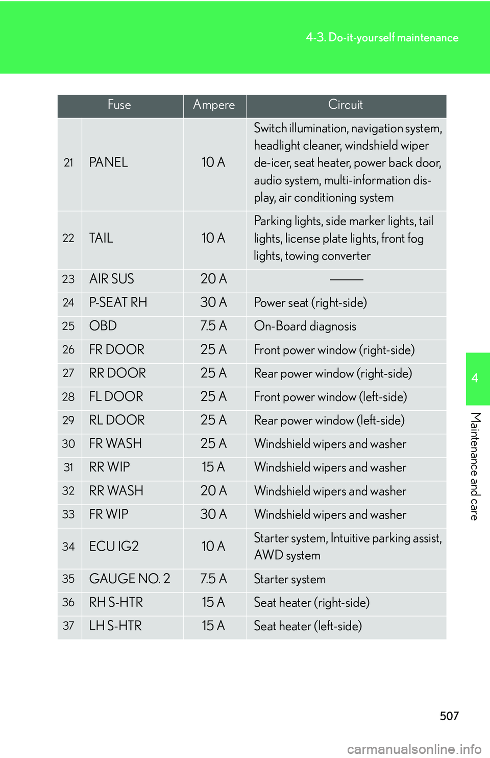
507
4-3. Do-it-yourself maintenance
4
Maintenance and care
21PA N E L10 A
Switch illumination, navigation system,
headlight cleaner, windshield wiper
de-icer, seat heater, power back door,
audio system, multi-information dis-
play, air conditioning system
22TA I L10 A
Parking lights, side marker lights, tail
lights, license plate lights, front fog
lights, towing converter
23AIR SUS20 A
24P-S E AT R H30 APower seat (right-side)
25OBD7. 5 AOn-Board diagnosis
26FR DOOR25 AFront power window (right-side)
27RR DOOR25 ARear power window (right-side)
28FL DOOR25 AFront power window (left-side)
29RL DOOR25 ARear power window (left-side)
30FR WASH25 AWindshield wipers and washer
31RR WIP15 AWindshield wipers and washer
32RR WASH20 AWindshield wipers and washer
33FR WIP30 AWindshield wipers and washer
34ECU IG210 AStarter system, Intuitive parking assist,
AWD s y s t e m
35GAUGE NO. 27. 5 AStarter system
36RH S-HTR15 ASeat heater (right-side)
37LH S-HTR15 ASeat heater (left-side)
FuseAmpereCircuit