check LEXUS SC300 1991 Service Owners Manual
[x] Cancel search | Manufacturer: LEXUS, Model Year: 1991, Model line: SC300, Model: LEXUS SC300 1991Pages: 4087, PDF Size: 75.75 MB
Page 143 of 4087
REPLACEMENT OF REFRIGERANT
LINES
1. RECOVER REFRIGERANT IN REFRIGERATION SYSTEMSee page AC±16
2. REPLACE FAULTY TUBE OR HOSE NOTICE: To prevent the intrusion of moisture or dirt, caps
should be placed on hose or tube ends immediately.
3. TORQUE CONNECTIONS TO SPECIFIED TORQUE
NOTICE: Connections should not be torque tighter than the
specified torque.
4. EVACUATE REFRIGERATION SYSTEM AND CHARGE WITH REFRIGERANT
See page AC±17
Specified amount: 950 + 50 g (33.44 + 1.76 oz)
5. INSPECT FOR LEAKAGE OF REFRIGERANT
Using a gas leak tester, check for leakage of refrigerant.
6. INSPECT A/C OPERATION
AC±106
±
AIR CONDITIONING SYSTEM Refrigerant Lines
WhereEverybodyKnowsYourName
Page 146 of 4087
9. INSTALL EVAPORATORSee page AC±124
10. INSTALL INSTRUMENT PANEL REINFORCEMENT
11. INSTALL ENGINE See page EM±167
12. E V ACUATE AIR IN REFRIGERATION SYSTEM AND
CHARGE WITH REFRIGERANT
See page AC±17
Specified amount: 950 + 50 g (33.44 + 1.76 oz)
13. INSPECT FOR LEAKAGE OF REFRIGERANT
Using a gas leak tester, check for leakage of refrigerant.
±
AIR CONDITIONING SYSTEM TroubleshootingAC±109
WhereEverybodyKnowsYourName
Page 147 of 4087
COMPRESSOR
INSPECTION OF COMPRESSOR
(Magnetic Clutch)
See page AC±86
(Compressor)
1. INSTALL MANIFOLD GAUGE SET
See page AC±15
2. START ENGINE
3. INSPECT COMPRESSOR FOR METALLIC SOUND Check that there is metallic sound from the compressor when
the A/C switch is turned on.
If a metallic sound is heard, replace the compressor assem-
bly.
4. INSPECT PRESSURE OF REFRIGERATION SYSTEM See ºInspection of Refrigeration System with Manifold
Gauge Setº on page.
5. STOP ENGINE
6. INSPECT VISUALLY FOR LEAKAGE OF REFRIGERANT FROM SAFETY SEAL
If there is any leakage, replace the compressor assembly.
AC±110
±
AIR CONDITIONING SYSTEM Troubleshooting
WhereEverybodyKnowsYourName
Page 153 of 4087
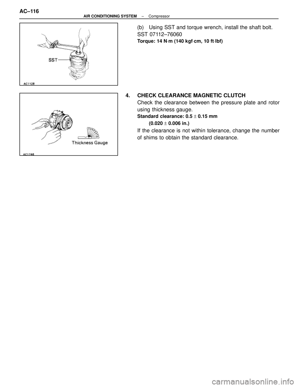
(b) Using SST and torque wrench, install the shaft bolt.SST 07112±76060
Torque: 14 N Vm (140 kgf Vcm, 10 ft Vlbf)
4. CHECK CLEARANCE MAGNETIC CLUTCH
Check the clearance between the pressure plate and rotor
using thickness gauge.
Standard clearance: 0.5 + 0.15 mm
(0.020 + 0.006 in.)
If the clearance is not within tolerance, change the number
of shims to obtain the standard clearance.
AC±116
±
AIR CONDITIONING SYSTEM Compressor
WhereEverybodyKnowsYourName
Page 154 of 4087
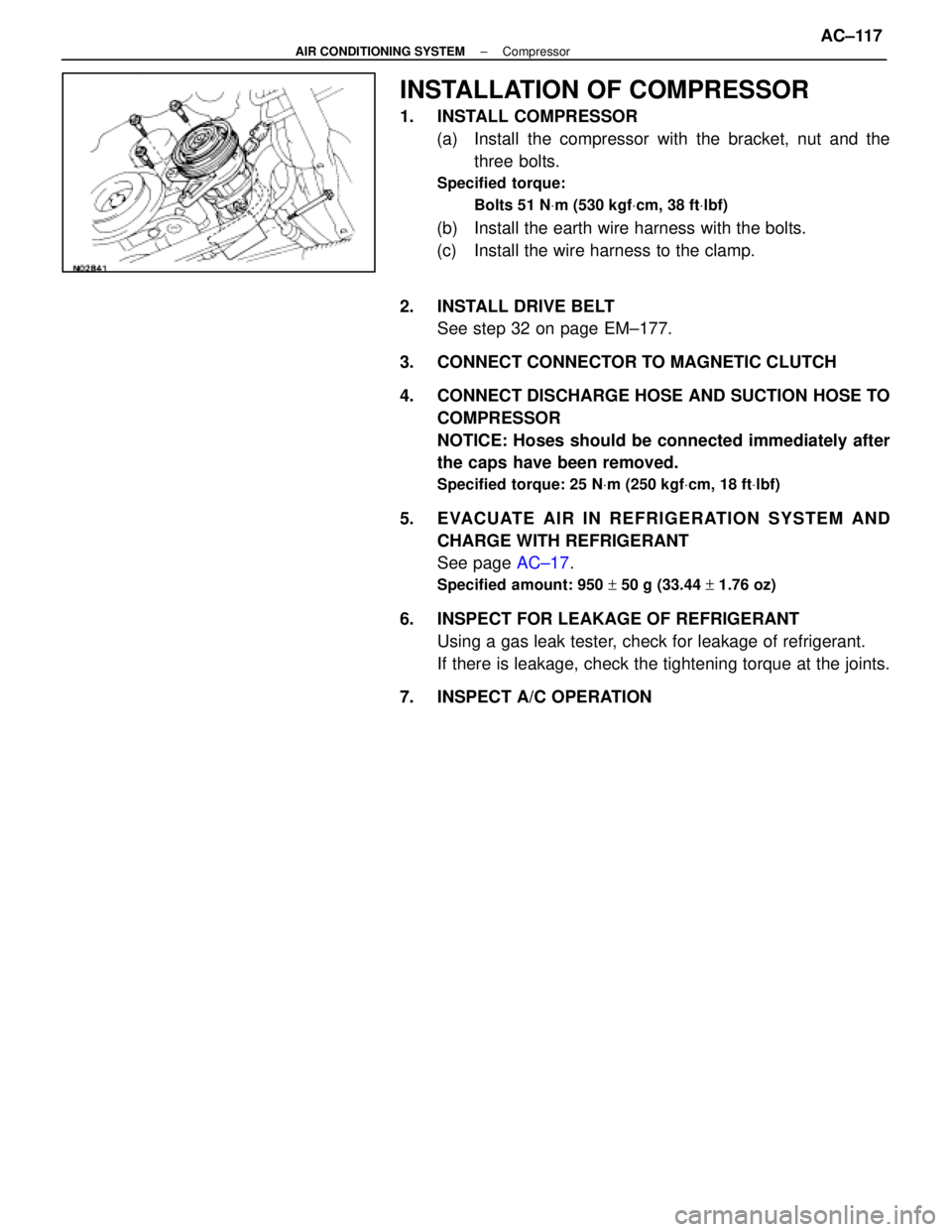
INSTALLATION OF COMPRESSOR
1. INSTALL COMPRESSOR(a) Install the compressor with the bracket, nut and the three bolts.
Specified torque:
Bolts 51 N Vm (530 kgf Vcm, 38 ft Vlbf)
(b) Install the earth wire harness with the bolts.
(c) Install the wire harness to the clamp.
2. INSTALL DRIVE BELT See step 32 on page EM±177.
3. CONNECT CONNECTOR TO MAGNETIC CLUTCH
4. CONNECT DISCHARGE HOSE AND SUCTION HOSE TO COMPRESSOR
NOTICE: Hoses should be connected immediately after
the caps have been removed.
Specified torque: 25 N Vm (250 kgf Vcm, 18 ft Vlbf)
5. EVACUATE AIR IN REFRIGERATION SYSTEM AND
CHARGE WITH REFRIGERANT
See page AC±17.
Specified amount: 950 + 50 g (33.44 + 1.76 oz)
6. INSPECT FOR LEAKAGE OF REFRIGERANT
Using a gas leak tester, check for leakage of refrigerant.
If there is leakage, check the tightening torque at the joints.
7. INSPECT A/C OPERATION
±
AIR CONDITIONING SYSTEM CompressorAC±117
WhereEverybodyKnowsYourName
Page 155 of 4087
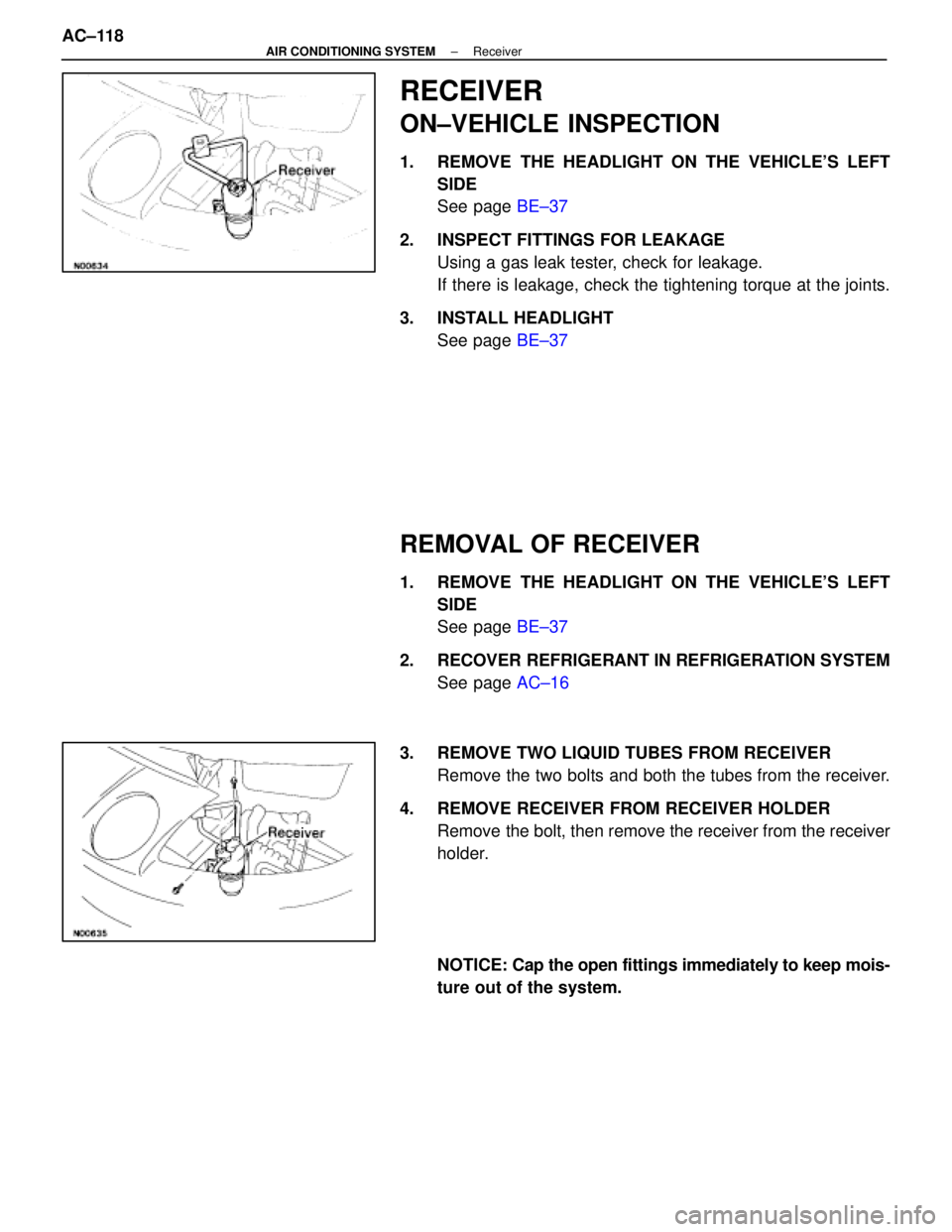
RECEIVER
ON±VEHICLE INSPECTION
1. REMOVE THE HEADLIGHT ON THE VEHICLE'S LEFTSIDE
See page BE±37
2. INSPECT FITTINGS FOR LEAKAGE Using a gas leak tester, check for leakage.
If there is leakage, check the tightening torque at the joints.
3. INSTALL HEADLIGHT See page BE±37
REMOVAL OF RECEIVER
1. REMOVE THE HEADLIGHT ON THE VEHICLE'S LEFT
SIDE
See page BE±37
2. RECOVER REFRIGERANT IN REFRIGERATION SYSTEM See page AC±16
3. REMOVE TWO LIQUID TUBES FROM RECEIVER Remove the two bolts and both the tubes from the receiver.
4. REMOVE RECEIVER FROM RECEIVER HOLDER Remove the bolt, then remove the receiver from the receiver
holder.
NOTICE: Cap the open fittings immediately to keep mois-
ture out of the system.
AC±118
±
AIR CONDITIONING SYSTEM Receiver
WhereEverybodyKnowsYourName
Page 156 of 4087
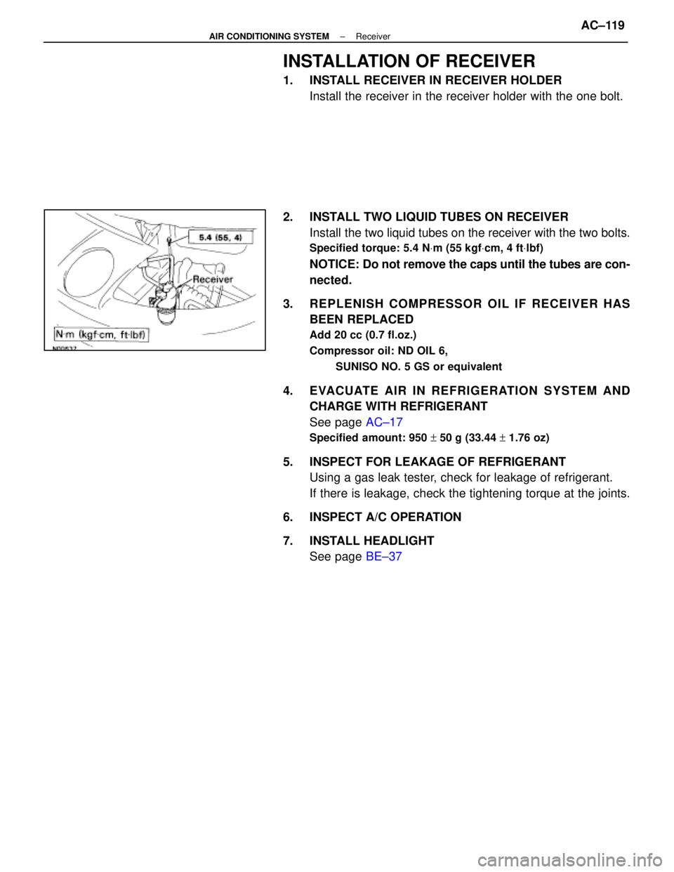
INSTALLATION OF RECEIVER
1. INSTALL RECEIVER IN RECEIVER HOLDERInstall the receiver in the receiver holder with the one bolt.
2. INSTALL TWO LIQUID TUBES ON RECEIVER Install the two liquid tubes on the receiver with the two bolts.
Specified torque: 5.4 N Vm (55 kgf Vcm, 4 ft Vlbf)
NOTICE: Do not remove the caps until the tubes are con-
nected.
3. REPLENISH COMPRESSOR OIL IF RECEIVER HAS BEEN REPLACED
Add 20 cc (0.7 fl.oz.)
Compressor oil: ND OIL 6,
SUNISO NO. 5 GS or equivalent
4. EVACUATE AIR IN REFRIGERATION SYSTEM ANDCHARGE WITH REFRIGERANT
See page AC±17
Specified amount: 950 + 50 g (33.44 + 1.76 oz)
5. INSPECT FOR LEAKAGE OF REFRIGERANT
Using a gas leak tester, check for leakage of refrigerant.
If there is leakage, check the tightening torque at the joints.
6. INSPECT A/C OPERATION
7. INSTALL HEADLIGHT See page BE±37
±
AIR CONDITIONING SYSTEM ReceiverAC±119
WhereEverybodyKnowsYourName
Page 157 of 4087
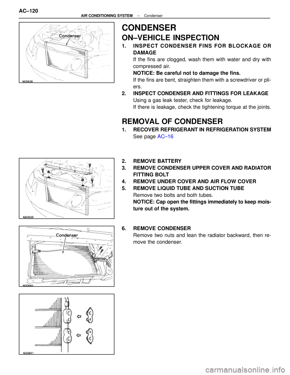
CONDENSER
ON±VEHICLE INSPECTION
1. INSPECT CONDENSER FINS FOR BLOCKAGE OR
DAMAGE
If the fins are clogged, wash them with water and dry with
compressed air.
NOTICE: Be careful not to damage the fins.
If the fins are bent, straighten them with a screwdriver or pli-
ers.
2. INSPECT CONDENSER AND FITTINGS FOR LEAKAGE Using a gas leak tester, check for leakage.
If there is leakage, check the tightening torque at the joints.
REMOVAL OF CONDENSER
1. RECOVER REFRIGERANT IN REFRIGERATION SYSTEMSee page AC±16
2. REMOVE BATTERY
3. REMOVE CONDENSER UPPER COVER AND RADIATOR FITTING BOLT
4. REMOVE UNDER COVER AND AIR FLOW COVER
5. REMOVE LIQUID TUBE AND SUCTION TUBE Remove two bolts and both tubes.
NOTICE: Cap open the fittings immediately to keep mois-
ture out of the system.
6. REMOVE CONDENSER Remove two nuts and lean the radiator backward, then re-
move the condenser.
AC±120
±
AIR CONDITIONING SYSTEM Condenser
WhereEverybodyKnowsYourName
Page 158 of 4087
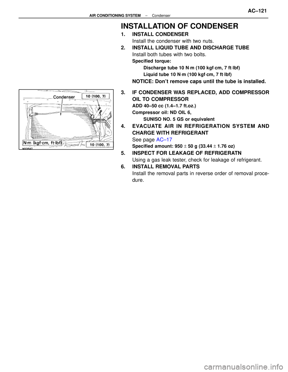
INSTALLATION OF CONDENSER
1. INSTALL CONDENSERInstall the condenser with two nuts.
2. INSTALL LIQUID TUBE AND DISCHARGE TUBE
Install both tubes with two bolts.
Specified torque:
Discharge tube 10 N Vm (100 kgf Vcm, 7 ft Vlbf)
Liquid tube 10 N Vm (100 kgf Vcm, 7 ft Vlbf)
NOTICE: Don't remove caps until the tube is installed.
3. IF CONDENSER WAS REPLACED, ADD COMPRESSOR OIL TO COMPRESSOR
ADD 40±50 cc (1.4±1.7 ft.oz.)
Compressor oil: ND OIL 6,
SUNISO NO. 5 GS or equivalent
4. EVACUATE AIR IN REFRIGERATION SYSTEM ANDCHARGE WITH REFRIGERANT
See page AC±17
Specified amount: 950 + 50 g (33.44 + 1.76 oz)
5. INSPECT FOR LEAKAGE OF REFRIGERATN
Using a gas leak tester, check for leakage of refrigerant.
6. INSTALL REMOVAL PARTS Install the removal parts in reverse order of removal proce-
dure.
±
AIR CONDITIONING SYSTEM CondenserAC±121
WhereEverybodyKnowsYourName
Page 161 of 4087
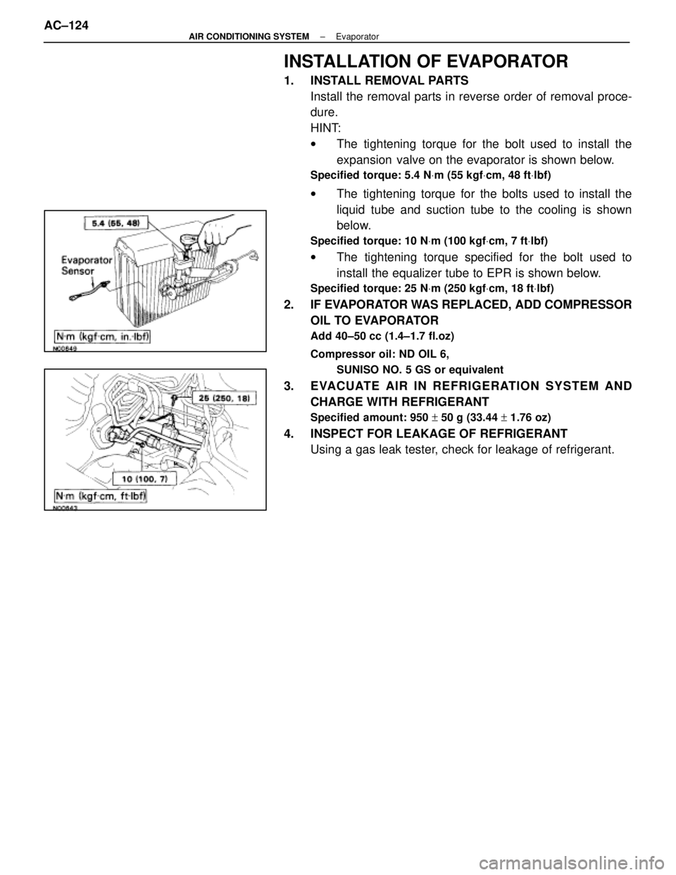
INSTALLATION OF EVAPORATOR
1. INSTALL REMOVAL PARTSInstall the removal parts in reverse order of removal proce-
dure.
HINT:
wThe tightening torque for the bolt used to install the
expansion valve on the evaporator is shown below.
Specified torque: 5.4 N Vm (55 kgf Vcm, 48 ft Vlbf)
w The tightening torque for the bolts used to install the
liquid tube and suction tube to the cooling is shown
below.
Specified torque: 10 N Vm (100 kgf Vcm, 7 ft Vlbf)
w The tightening torque specified for the bolt used to
install the equalizer tube to EPR is shown below.
Specified torque: 25 N Vm (250 kgf Vcm, 18 ft Vlbf)
2. IF EVAPORATOR WAS REPLACED, ADD COMPRESSOR
OIL TO EVAPORATOR
Add 40±50 cc (1.4±1.7 fl.oz)
Compressor oil: ND OIL 6,
SUNISO NO. 5 GS or equivalent
3. EVACUATE AIR IN REFRIGERATION SYSTEM ANDCHARGE WITH REFRIGERANT
Specified amount: 950 + 50 g (33.44 + 1.76 oz)
4. INSPECT FOR LEAKAGE OF REFRIGERANT
Using a gas leak tester, check for leakage of refrigerant.
AC±124
±
AIR CONDITIONING SYSTEM Evaporator
WhereEverybodyKnowsYourName