LEXUS SC400 1991 Service Repair Manual
Manufacturer: LEXUS, Model Year: 1991,
Model line: SC400,
Model: LEXUS SC400 1991
Pages: 4087, PDF Size: 75.75 MB
LEXUS SC400 1991 Service Repair Manual
SC400 1991
LEXUS
LEXUS
https://www.carmanualsonline.info/img/36/57051/w960_57051-0.png
LEXUS SC400 1991 Service Repair Manual
Trending: brake fluid, check engine, refrigerant type, tow, odometer, drain bolt, compression ratio
Page 1101 of 4087
WIRING DIAGRAM
DTC55Brake Fluid Level Warning Switch Circuit
CIRCUIT DESCRIPTION
The brake fluid level warning switch sends the appropriate signal to the EC\
U when the brake fluid level drops.
DTC No.DTC Detecting ConditionTrouble Area
55Voltage at ECU terminal LBL is 0Vcontinuously for 10
sec. or more.
Brake fluid level.
Brake fluid level warning switch.
Short in brake fluid level warning switchcircuit.
ECU
Fail safe function: If trouble occurs in this circuit, the ECU cuts off current to the TRAC solenoid relay
and prohibits TRAC control.
DIAGNOSTIC CHARTDIAGNOSTIC CHART
BR±132±
BRAKE SYSTEM ANTI±LOCK BRAKE SYSTEM (ABS)
WhereEverybodyKnowsYourName
Page 1102 of 4087
OKNG
OKNG
OKNG
INSPECTION PROCEDURE
1Check brake fluid level.
Check the amount of fluid in the bake reservoir.C
Check and repair brake fluid leakage and add fluid.
2Check brake fluid level warning switch.
See page BE±142.
Replace brake fluid level warning switch.
3Check for short in all the harness and components connected to brake fluid le\
vel warning light
(See page IN±33).
Repair or replace harness or connector.
Check and replace ABS & TRAC ECU.
±
BRAKE SYSTEM ANTI±LOCK BRAKE SYSTEM (ABS)BR±133
WhereEverybodyKnowsYourName
Page 1103 of 4087
DTC56, 57Pressure Sensor Circuit
CIRCUIT DESCRIPTION
The pressure sensor detects the TRAC accumulator hydraulic pressure and if \
it is low, it sends signals to the
ECU to operate the pump. If the pressure is high, it sends signals to th\
e ECU to stop the pump.
DTC No.DTC Detecting ConditionTrouble Area
56Pressure sensor terminal PR outputs below 1 V for
about 1 sec. or more.
Open or short in pressure sensor circuit.
57
TRAC (BRAKE) control is executed continuouslymore
than 255 times while pressure sensor ONsignal is not
output.
Pressure sensor
Fail safe function: If trouble occurs in the pressure sensor circuit, the ECU cuts off current to the TRAC
solenoid relay and prohibits TRAC control.
BR±134
±
BRAKE SYSTEM ANTI±LOCK BRAKE SYSTEM (ABS)
WhereEverybodyKnowsYourName
Page 1104 of 4087
WIRING DIAGRAM
DIAGNOSTIC CHARTDIAGNOSTIC CHART
±
BRAKE SYSTEM ANTI±LOCK BRAKE SYSTEM (ABS)BR±135
WhereEverybodyKnowsYourName
Page 1105 of 4087
NGOK
OKNG
INSPECTION PROCEDURE
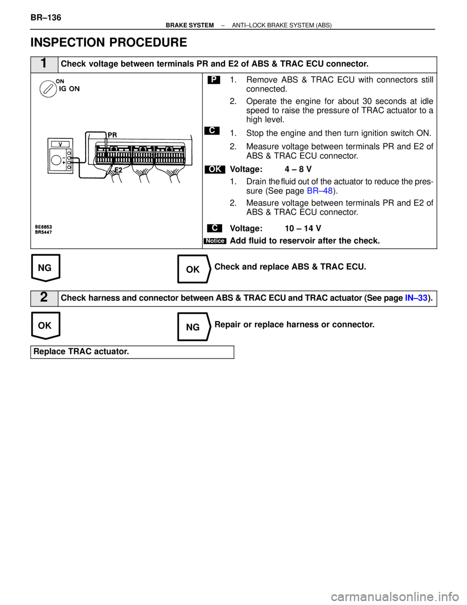
1Check voltage between terminals PR and E2 of ABS & TRAC ECU connector.
C
OK
P
C
Notice
1. Remove ABS & TRAC ECU with connectors stillconnected.
2. Operate the engine for about 30 seconds at idle speed to raise the pressure of TRAC actuator to a
high level.
1. Stop the engine and then turn ignition switch ON.
2. Measure voltage between terminals PR and E2 of ABS & TRAC ECU connector.
Voltage: 4 ± 8 V
1. Drain the fluid out of the actuator to reduce the pres-
sure (See page BR±48).
2. Measure voltage between terminals PR and E2 of ABS & TRAC ECU connector.
Voltage: 10 ± 14 V
Add fluid to reservoir after the check.
Check and replace ABS & TRAC ECU.
2Check harness and connector between ABS & TRAC ECU and TRAC actuator (See page IN±33).
Repair or replace harness or connector.
Replace TRAC actuator.
BR±136±
BRAKE SYSTEM ANTI±LOCK BRAKE SYSTEM (ABS)
WhereEverybodyKnowsYourName
Page 1106 of 4087
±MEMO±
±
BRAKE SYSTEM ANTI±LOCK BRAKE SYSTEM (ABS)BR±137
WhereEverybodyKnowsYourName
Page 1107 of 4087
WIRING DIAGRAM
DTC61TRAC ECU Communication Circuit Malfunc-
tion.
CIRCUIT DESCRIPTION
DTC No.DTC Detecting ConditionTrouble Area
61
Either of the following (1) or (2) continues for more than
8 sec.:
(1) Vehicle speed signal of 4 wheels is less than 1 km/h
(1 mph) when TRCO signal is input.
(2) THFA signal is 0V when TRCO signal is not input.
Open or short in THFA, TRCO circuit
ABS & TRAC ECU
TRAC ECU
DIAGNOSTIC CHARTDIAGNOSTIC CHART
BR±138±
BRAKE SYSTEM ANTI±LOCK BRAKE SYSTEM (ABS)
WhereEverybodyKnowsYourName
Page 1108 of 4087
OKOK
OKNG
OKNG
INSPECTION PROCEDURE
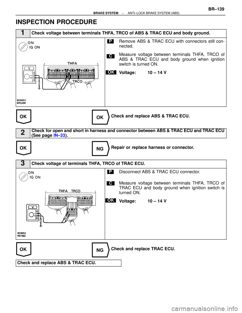
1Check voltage between terminals THFA, TRCO of ABS & TRAC ECU and body ground.
C
OK
PRemove ABS & TRAC ECU with connectors still con-
nected.
Measure voltage between terminals THFA, TRCO of
ABS & TRAC ECU and body ground when ignition
switch is turned ON.
Voltage: 10 ± 14 V
Check and replace ABS & TRAC ECU.
2Check for open and short in harness and connector between ABS & TRAC ECU and TRAC ECU
(See page IN±33).
Repair or replace harness or connector.
3Check voltage of terminals THFA, TRCO of TRAC ECU.
C
OK
PDisconnect ABS & TRAC ECU connector.
Measure voltage between terminals THFA, TRCO of
TRAC ECU and body ground when ignition switch is
turned ON.
Voltage: 10 ± 14 V
Check and replace TRAC ECU.
Check and replace ABS & TRAC ECU.
±
BRAKE SYSTEM ANTI±LOCK BRAKE SYSTEM (ABS)BR±139
WhereEverybodyKnowsYourName
Page 1109 of 4087
DTC62TRAC Vehicle Speed Malfunction
CIRCUIT DESCRIPTION
DTC No.DTC Detecting ConditionTrouble Area
62
Detection of any of conditions (1) through (3):At vehicle speed of 10 km/h (6 mph) or more, pulses
are not input for 5 sec.
ECU
HINT: When DTC Nos. 31±36 are recorded in memory, DTC No. 62 is not recorded.
DIAGNOSTIC CHARTDIAGNOSTIC CHART
BR±140±
BRAKE SYSTEM ANTI±LOCK BRAKE SYSTEM (ABS)
WhereEverybodyKnowsYourName
Page 1110 of 4087
±MEMO±
±
BRAKE SYSTEM ANTI±LOCK BRAKE SYSTEM (ABS)BR±141
WhereEverybodyKnowsYourName
Trending: dashboard, trip computer, radio antenna, oil temperature, spark plugs replace, instrument cluster, warning light


