LEXUS SC400 1991 Service Repair Manual
Manufacturer: LEXUS, Model Year: 1991, Model line: SC400, Model: LEXUS SC400 1991Pages: 4087, PDF Size: 75.75 MB
Page 1711 of 4087
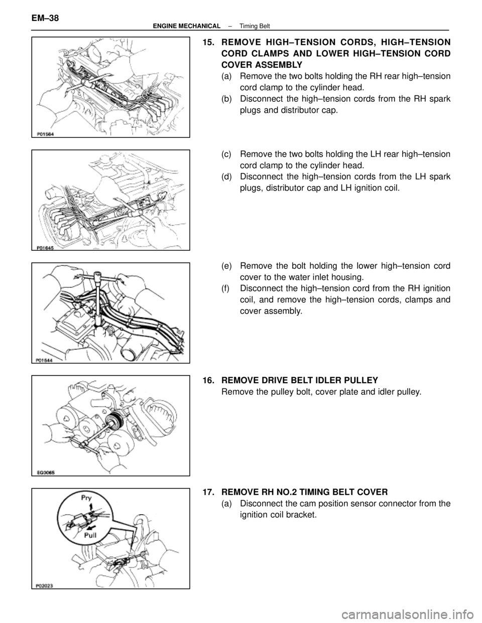
15. REMOVE HIGH±TENSION CORDS, HIGH±TENSIONCORD CLAMPS AND LOWER HIGH±TENSION CORD
COVER ASSEMBLY
(a) Remove the two bolts holding the RH rear high±tensioncord clamp to the cylinder head.
(b) Disconnect the high±tension cords from the RH spark plugs and distributor cap.
(c) Remove the two bolts holding the LH rear high±tension cord clamp to the cylinder head.
(d) Disconnect the high±tension cords from the LH spark
plugs, distributor cap and LH ignition coil.
(e) Remove the bolt holding the lower high±tension cord cover to the water inlet housing.
(f) Disconnect the high±tension cord from the RH ignition
coil, and remove the high±tension cords, clamps and
cover assembly.
16. REMOVE DRIVE BELT IDLER PULLEY Remove the pulley bolt, cover plate and idler pulley.
17. REMOVE RH NO.2 TIMING BELT COVER (a) Disconnect the cam position sensor connector from theignition coil bracket.
EM±38
±
ENGINE MECHANICAL Timing Belt
WhereEverybodyKnowsYourName
Page 1712 of 4087
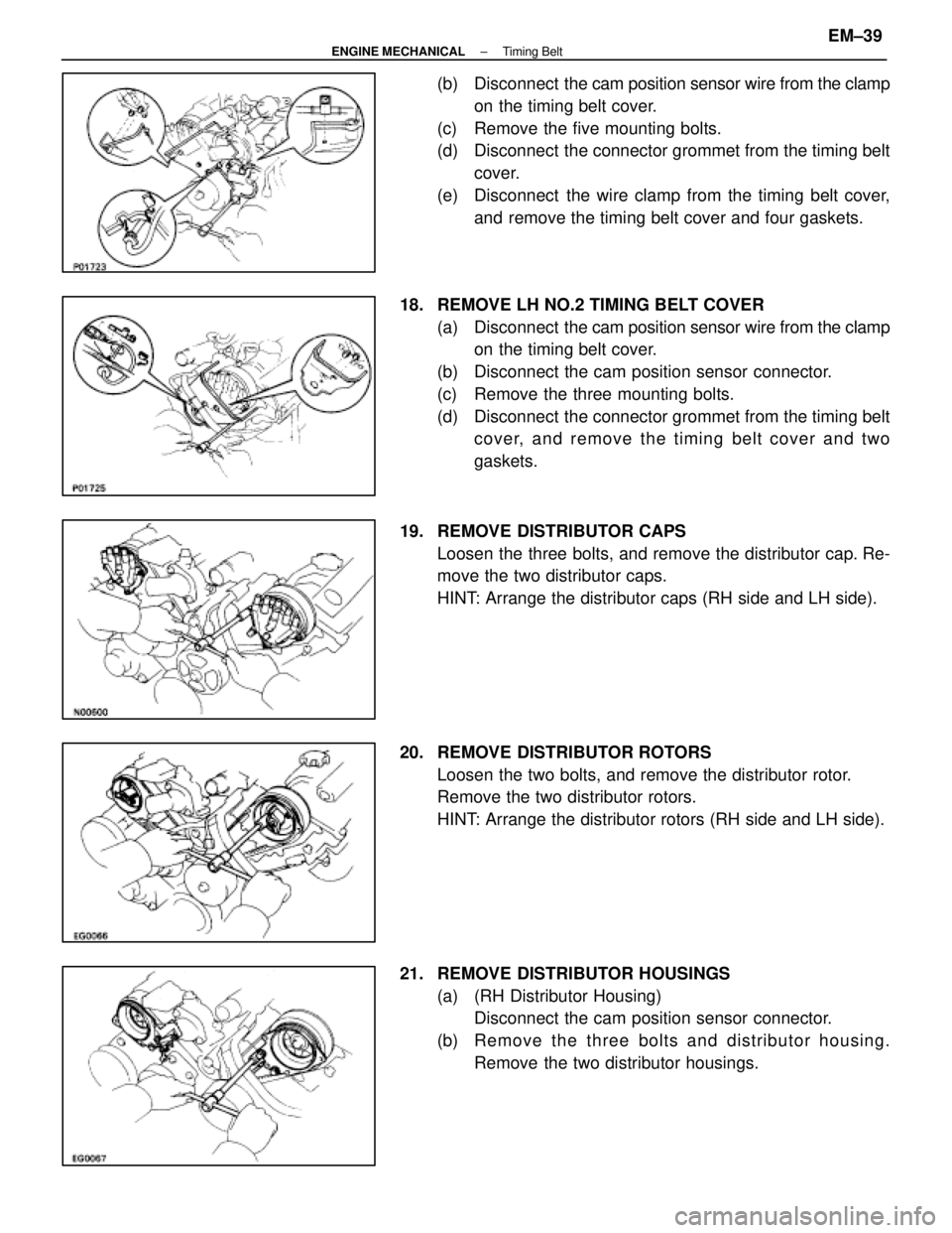
(b) Disconnect the cam position sensor wire from the clamp
on the timing belt cover.
(c) Remove the five mounting bolts.
(d) Disconnect the connector grommet from the timing belt cover.
(e) Disconnect the wire clamp from the timing belt cover, and remove the timing belt cover and four gaskets.
18. REMOVE LH NO.2 TIMING BELT COVER (a) Disconnect the cam position sensor wire from the clamp
on the timing belt cover.
(b) Disconnect the cam position sensor connector.
(c) Remove the three mounting bolts.
(d) Disconnect the connector grommet from the timing belt cover, and remove the timing belt cover and two
gaskets.
19. REMOVE DISTRIBUTOR CAPS Loosen the three bolts, and remove the distributor cap. Re-
move the two distributor caps.
HINT: Arrange the distributor caps (RH side and LH side).
20. REMOVE DISTRIBUTOR ROTORS Loosen the two bolts, and remove the distributor rotor.
Remove the two distributor rotors.
HINT: Arrange the distributor rotors (RH side and LH side).
21. REMOVE DISTRIBUTOR HOUSINGS (a) (RH Distributor Housing)Disconnect the cam position sensor connector.
(b) Re mo ve th e th re e bo lts an d distrib u to r ho u sin g . Remove the two distributor housings.
±
ENGINE MECHANICAL Timing BeltEM±39
WhereEverybodyKnowsYourName
Page 1713 of 4087
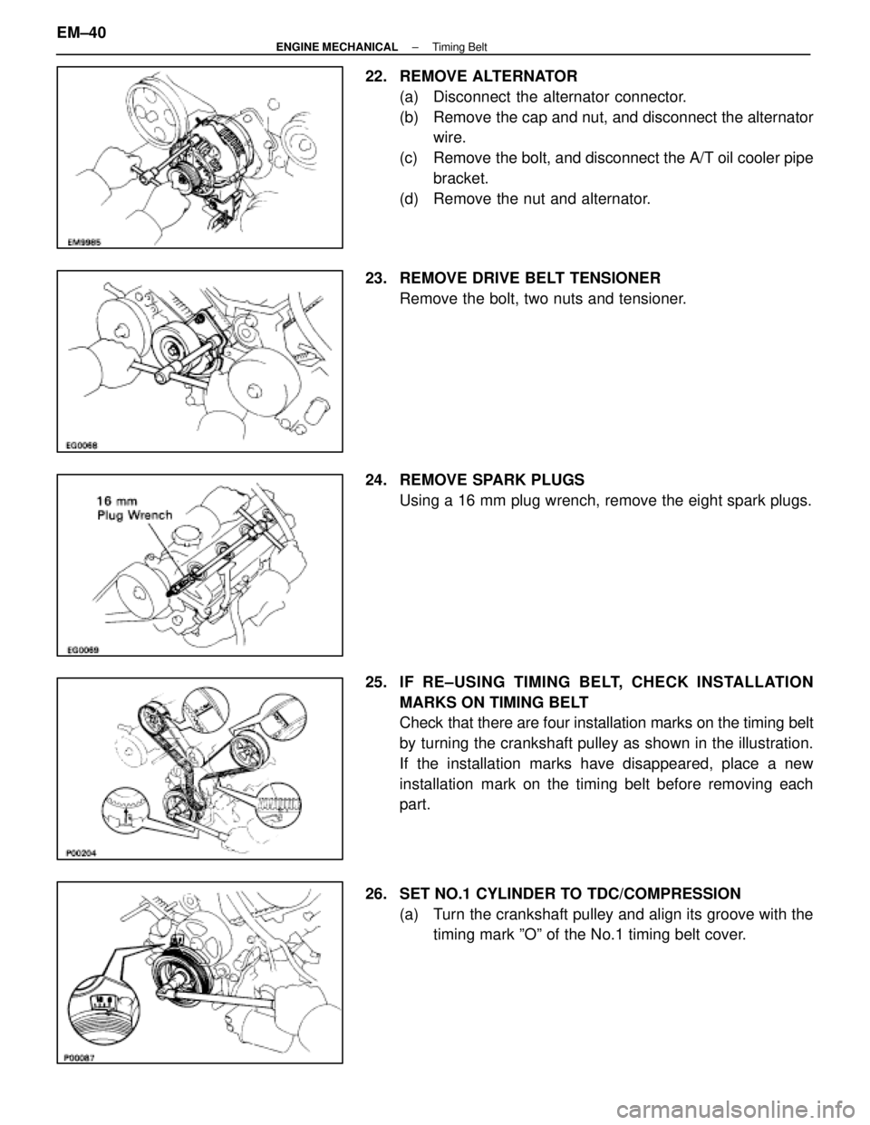
22. REMOVE ALTERNATOR(a) Disconnect the alternator connector.
(b) Remove the cap and nut, and disconnect the alternatorwire.
(c) Remove the bolt, and disconnect the A/T oil cooler pipe bracket.
(d) Remove the nut and alternator.
23. REMOVE DRIVE BELT TENSIONER Remove the bolt, two nuts and tensioner.
24. REMOVE SPARK PLUGS Using a 16 mm plug wrench, remove the eight spark plugs.
25. IF RE±USING TIMING BELT, CHECK INSTALLATION MARKS ON TIMING BELT
Check that there are four installation marks on the timing belt
by turning the crankshaft pulley as shown in the illustration.
If the installation marks have disappeared, place a new
installation mark on the timing belt before removing each
part.
26. SET NO.1 CYLINDER TO TDC/COMPRESSION (a) Turn the crankshaft pulley and align its groove with thetiming mark ºOº of the No.1 timing belt cover.
EM±40
±
ENGINE MECHANICAL Timing Belt
WhereEverybodyKnowsYourName
Page 1714 of 4087
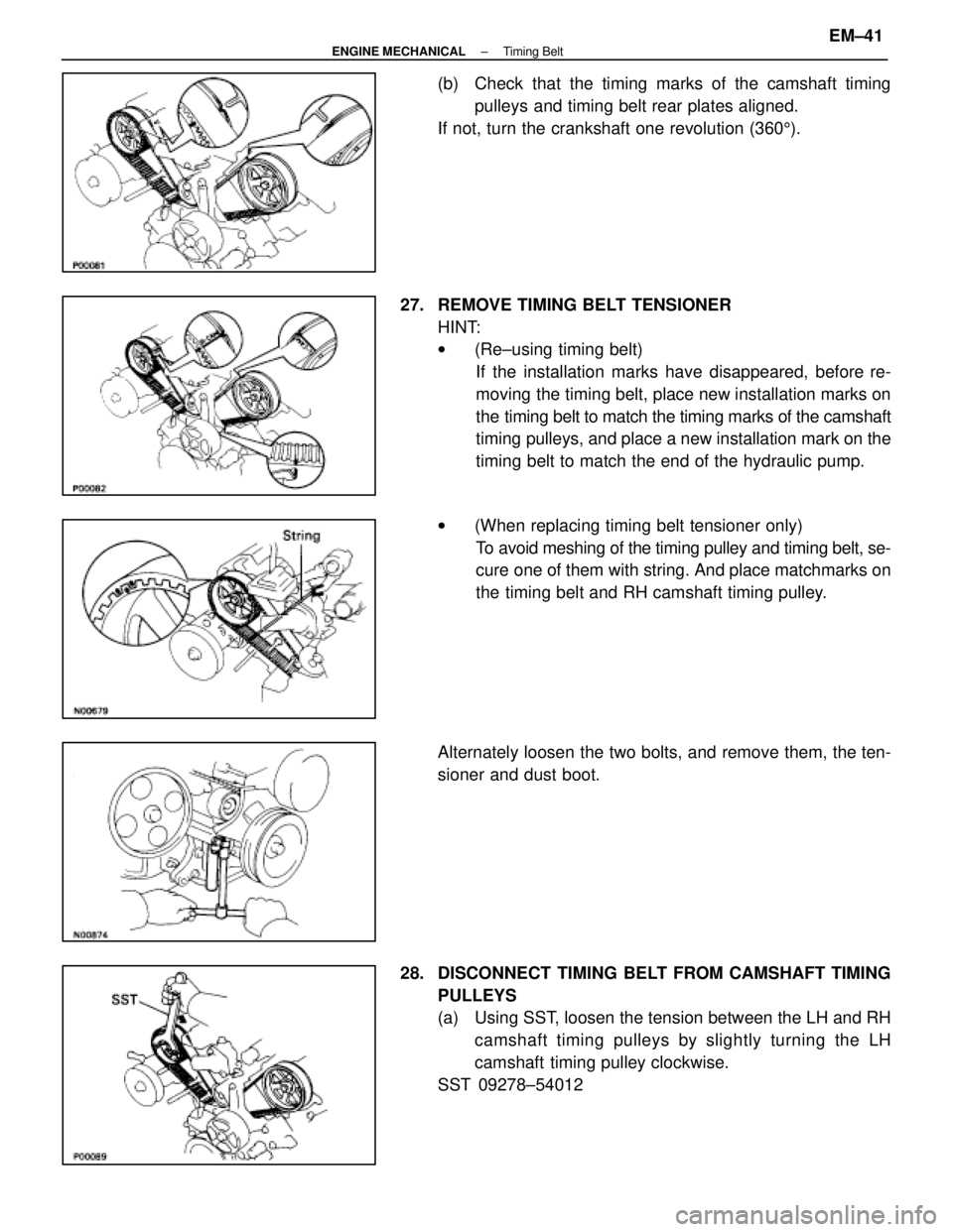
(b) Check that the timing marks of the camshaft timingpulleys and timing belt rear plates aligned.
If not, turn the crankshaft one revolution (360 5).
27. REMOVE TIMING BELT TENSIONER HINT:
w(Re±using timing belt)
If the installation marks have disappeared, before re-
moving the timing belt, place new installation marks on
the timing belt to match the timing marks of the camshaft
timing pulleys, and place a new installation mark on the
timing belt to match the end of the hydraulic pump.
w (When replacing timing belt tensioner only)
To avoid meshing of the timing pulley and timing belt, se-
cure one of them with string. And place matchmarks on
the timing belt and RH camshaft timing pulley.
Alternately loosen the two bolts, and remove them, the ten-
sioner and dust boot.
28. DISCONNECT TIMING BELT FROM CAMSHAFT TIMING PULLEYS
(a) Using SST, loosen the tension between the LH and RHcamshaft timing pulleys by slightly turning the LH
camshaft timing pulley clockwise.
SST 09278±54012
±
ENGINE MECHANICAL Timing BeltEM±41
WhereEverybodyKnowsYourName
Page 1715 of 4087
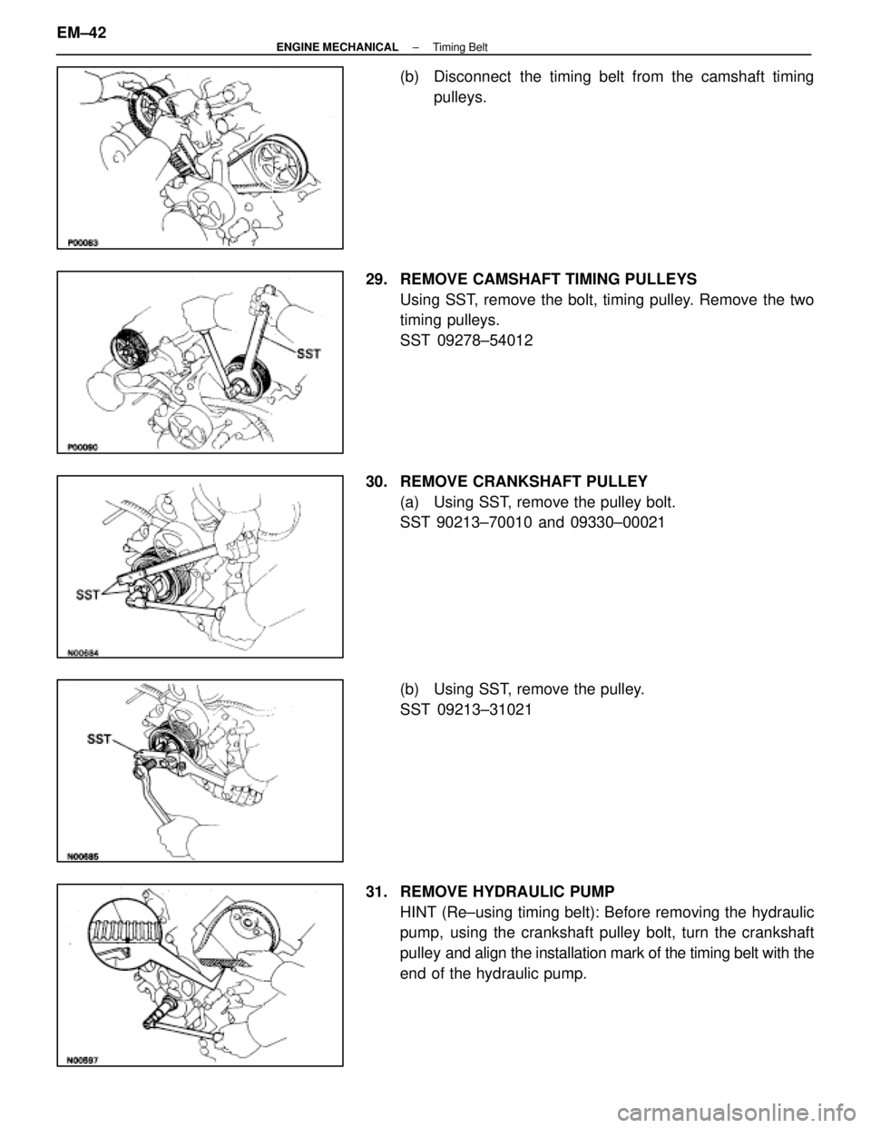
(b) Disconnect the timing belt from the camshaft timingpulleys.
29. REMOVE CAMSHAFT TIMING PULLEYS Using SST, remove the bolt, timing pulley. Remove the two
timing pulleys.
SST 09278±54012
30. REMOVE CRANKSHAFT PULLEY (a) Using SST, remove the pulley bolt.
SST 90213±70010 and 09330±00021
(b) Using SST, remove the pulley.
SST 09213±31021
31. REMOVE HYDRAULIC PUMP HINT (Re±using timing belt): Before removing the hydraulic
pump, using the crankshaft pulley bolt, turn the crankshaft
pulley and align the installation mark of the timing belt with the
end of the hydraulic pump.
EM±42
±
ENGINE MECHANICAL Timing Belt
WhereEverybodyKnowsYourName
Page 1716 of 4087
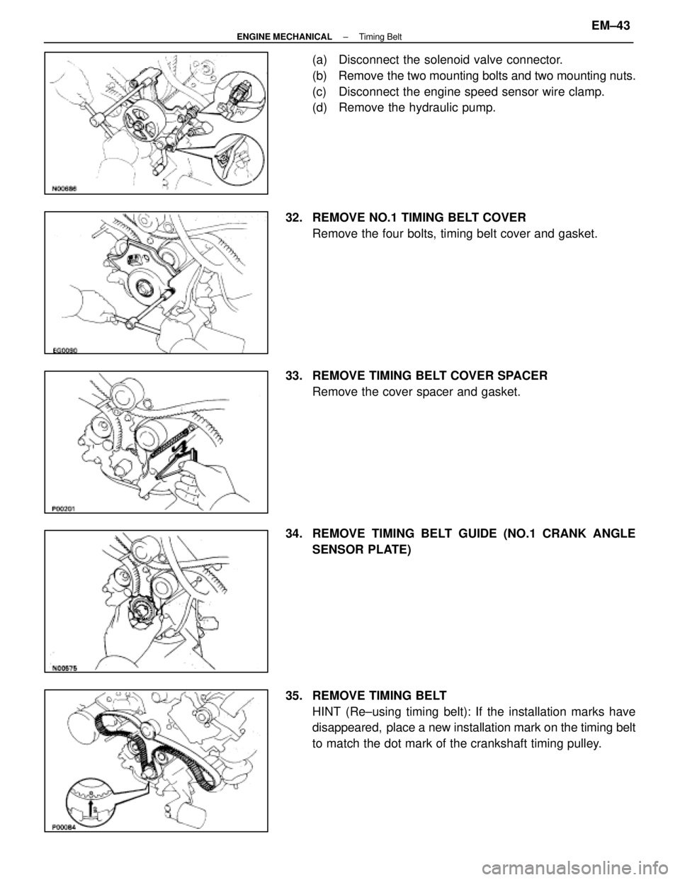
(a) Disconnect the solenoid valve connector.
(b) Remove the two mounting bolts and two mounting nuts.
(c) Disconnect the engine speed sensor wire clamp.
(d) Remove the hydraulic pump.
32. REMOVE NO.1 TIMING BELT COVER Remove the four bolts, timing belt cover and gasket.
33. REMOVE TIMING BELT COVER SPACER Remove the cover spacer and gasket.
34. REMOVE TIMING BELT GUIDE (NO.1 CRANK ANGLE SENSOR PLATE)
35. REMOVE TIMING BELT HINT (Re±using timing belt): If the installation marks have
disappeared, place a new installation mark on the timing belt
to match the dot mark of the crankshaft timing pulley.
±
ENGINE MECHANICAL Timing BeltEM±43
WhereEverybodyKnowsYourName
Page 1717 of 4087
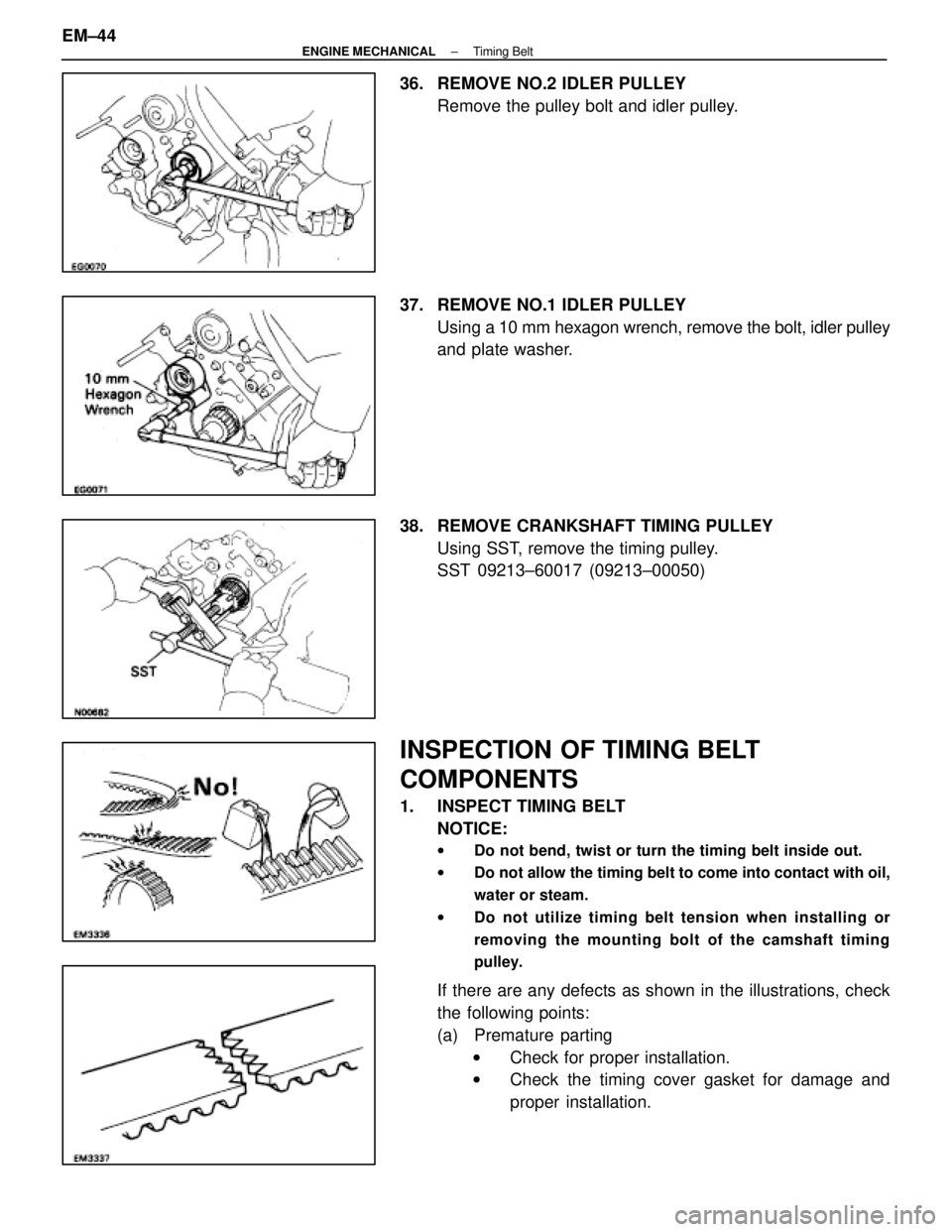
36. REMOVE NO.2 IDLER PULLEYRemove the pulley bolt and idler pulley.
37. REMOVE NO.1 IDLER PULLEY Using a 10 mm hexagon wrench, remove the bolt, idler pulley
and plate washer.
38. REMOVE CRANKSHAFT TIMING PULLEY Using SST, remove the timing pulley.
SST 09213±60017 (09213±00050)
INSPECTION OF TIMING BELT
COMPONENTS
1. INSPECT TIMING BELTNOTICE:
w Do not bend, twist or turn the timing belt inside out.
w Do not allow the timing belt to come into contact with oil,
water or steam.
w Do not utilize timing belt tension when installing or
removing the mounting bolt of the camshaft timing
pulley.
If there are any defects as shown in the illustrations, check
the following points:
(a) Premature parting
w Check for proper installation.
w Check the timing cover gasket for damage and
proper installation.
EM±44
±
ENGINE MECHANICAL Timing Belt
WhereEverybodyKnowsYourName
Page 1718 of 4087
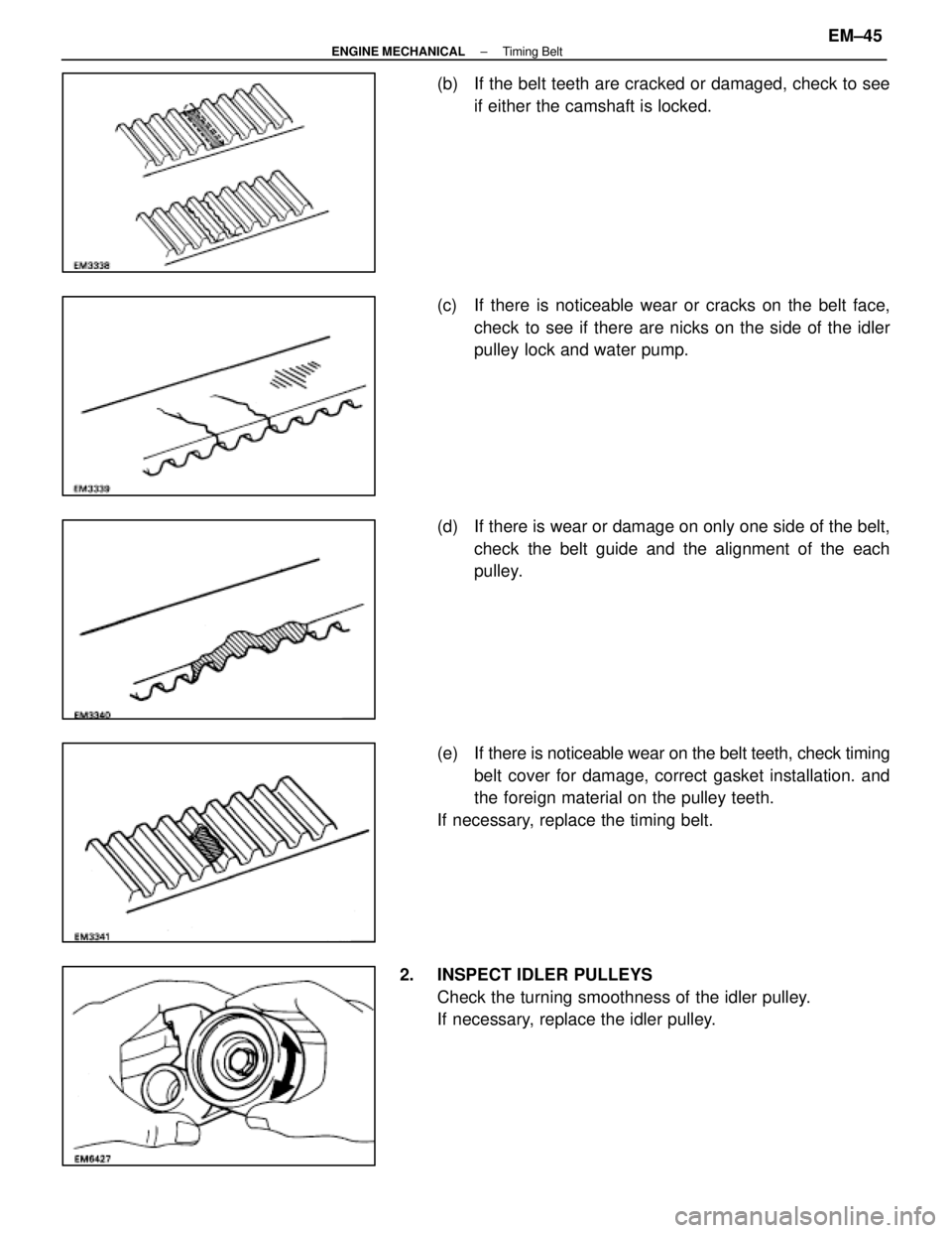
(b) If the belt teeth are cracked or damaged, check to seeif either the camshaft is locked.
(c) If there is noticeable wear or cracks on the belt face, check to see if there are nicks on the side of the idler
pulley lock and water pump.
(d) If there is wear or damage on only one side of the belt, check the belt guide and the alignment of the each
pulley.
(e) If there is noticeable wear on the belt teeth, check timing belt cover for damage, correct gasket installation. and
the foreign material on the pulley teeth.
If necessary, replace the timing belt.
2. INSPECT IDLER PULLEYS Check the turning smoothness of the idler pulley.
If necessary, replace the idler pulley.
±
ENGINE MECHANICAL Timing BeltEM±45
WhereEverybodyKnowsYourName
Page 1719 of 4087
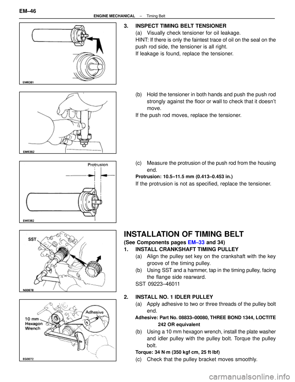
3. INSPECT TIMING BELT TENSIONER(a) Visually check tensioner for oil leakage.
HINT: If there is only the faintest trace of oil on the seal on the
push rod side, the tensioner is all right.
If leakage is found, replace the tensioner.
(b) Hold the tensioner in both hands and push the push rodstrongly against the floor or wall to check that it doesn't
move.
If the push rod moves, replace the tensioner.
(c) Measure the protrusion of the push rod from the housing
end.
Protrusion: 10.5±11.5 mm (0.413±0.453 in.)
If the protrusion is not as specified, replace the tensioner.
INSTALLATION OF TIMING BELT
(See Components pages EM±33 and 34)
1. INSTALL CRANKSHAFT TIMING PULLEY (a) Align the pulley set key on the crankshaft with the keygroove of the timing pulley.
(b) Using SST and a hammer, tap in the timing pulley, facing
the flange side rearward.
SST 09223±46011
2. INSTALL NO. 1 IDLER PULLEY (a) Apply adhesive to two or three threads of the pulley boltend.
Adhesive: Part No. 08833±00080, THREE BOND 1344, LOCTITE
242 OR equivalent
(b) Using a 10 mm hexagon wrench, install the plate washer
and idler pulley with the pulley bolt. Torque the pulley
bolt.
Torque: 34 N Vm (350 kgf Vcm, 25 ft Vlbf)
(c) Check that the pulley bracket moves smoothly.
EM±46
±
ENGINE MECHANICAL Timing Belt
WhereEverybodyKnowsYourName
Page 1720 of 4087
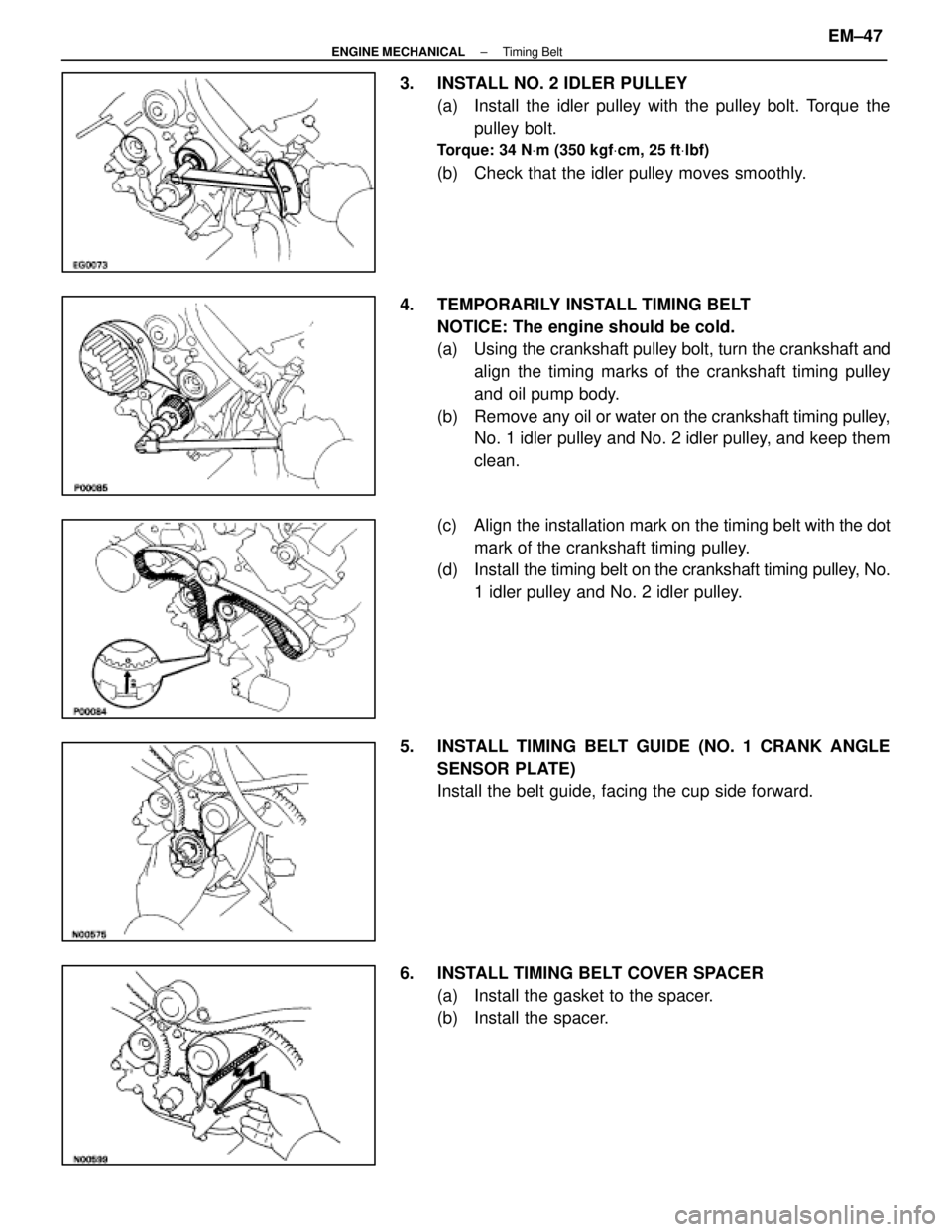
3. INSTALL NO. 2 IDLER PULLEY(a) Install the idler pulley with the pulley bolt. Torque thepulley bolt.
Torque: 34 N Vm (350 kgf Vcm, 25 ft Vlbf)
(b) Check that the idler pulley moves smoothly.
4. TEMPORARILY INSTALL TIMING BELT NOTICE: The engine should be cold.
(a) Using the crankshaft pulley bolt, turn the crankshaft andalign the timing marks of the crankshaft timing pulley
and oil pump body.
(b) Remove any oil or water on the crankshaft timing pulley,
No. 1 idler pulley and No. 2 idler pulley, and keep them
clean.
(c) Align the installation mark on the timing belt with the dot
mark of the crankshaft timing pulley.
(d) Install the timing belt on the crankshaft timing pulley, No.
1 idler pulley and No. 2 idler pulley.
5. INSTALL TIMING BELT GUIDE (NO. 1 CRANK ANGLE SENSOR PLATE)
Install the belt guide, facing the cup side forward.
6. INSTALL TIMING BELT COVER SPACER (a) Install the gasket to the spacer.
(b) Install the spacer.
±
ENGINE MECHANICAL Timing BeltEM±47
WhereEverybodyKnowsYourName