LEXUS SC400 1991 Service Repair Manual
Manufacturer: LEXUS, Model Year: 1991, Model line: SC400, Model: LEXUS SC400 1991Pages: 4087, PDF Size: 75.75 MB
Page 231 of 4087
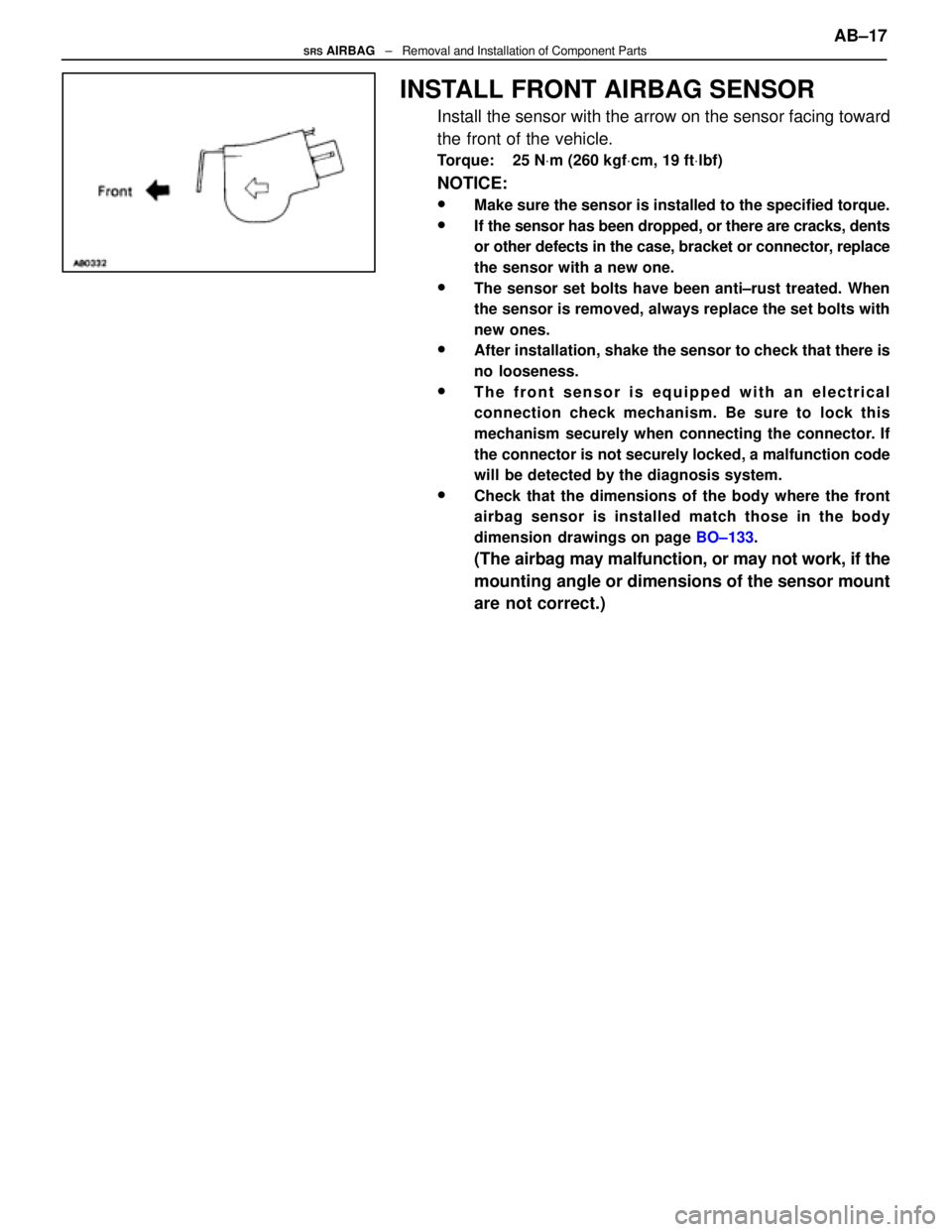
INSTALL FRONT AIRBAG SENSOR
Install the sensor with the arrow on the sensor facing toward
the front of the vehicle.
Torque: 25 NVm (260 kgf Vcm, 19 ft Vlbf)
NOTICE:
wMake sure the sensor is installed to the specified torque.
wIf the sensor has been dropped, or there are cracks, dents
or other defects in the case, bracket or connector, replace
the sensor with a new one.
wThe sensor set bolts have been anti±rust treated. When
the sensor is removed, always replace the set bolts with
new ones.
wAfter installation, shake the sensor to check that there is
no looseness.
wThe front sensor is equipped with an electrical
connection check mechanism. Be sure to lock this
mechanism securely when connecting the connector. If
the connector is not securely locked, a malfunction code
will be detected by the diagnosis system.
wCheck that the dimensions of the body where the front
airbag sensor is installed match those in the body
dimension drawings on page BO±133.
(The airbag may malfunction, or may not work, if the
mounting angle or dimensions of the sensor mount
are not correct.) AB±17
SRS AIRBAG
± Removal and Installation of Component Parts
WhereEverybodyKnowsYourName
Page 232 of 4087
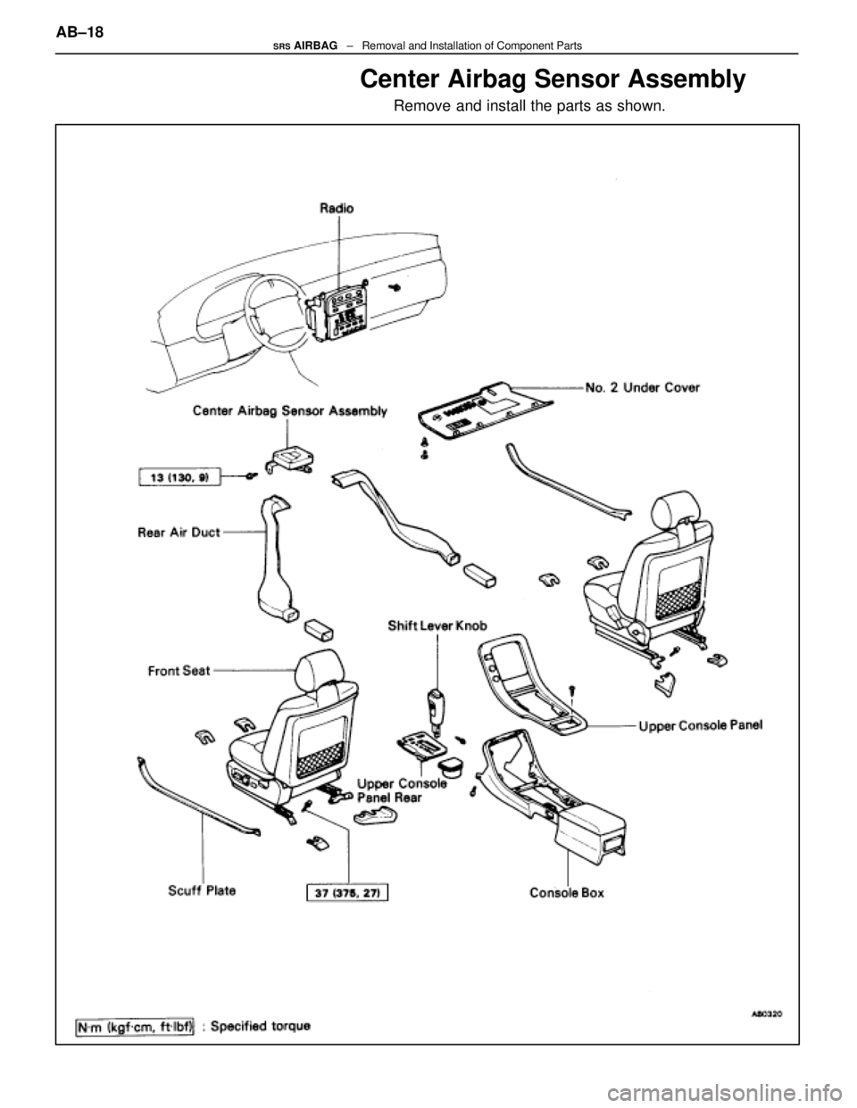
Center Airbag Sensor Assembly
Remove and install the parts as shown.
AB±18SRS AIRBAG ± Removal and Installation of Component Parts
WhereEverybodyKnowsYourName
Page 233 of 4087
(MAIN POINTS OF REMOVAL AND
INSTALLATION)
CAUTION: Work must be started after approx. 20 se-
conds or longer from the time the ignition switch is
turned to the LOCK position and the negative (±) terminal
cable is disconnected from the battery (See page AB±2).
NOTICE:
wDo not open the cover or the case of the ECU and various
computers unless absolutely necessary. (If the IC termi-
nals are touched, the IC may be destroyed by static elec-
tricity.)
wNever use airbag parts from another vehicle. When
replacing parts, replace with new parts.
wNever reuse the center airbag sensor assembly involved
in a collision when the airbag has deployed.
wNever repair a sensor in order to reuse it.
REMOVE AND INSTALL CENTER
AIRBAG SENSOR ASSEMBLY
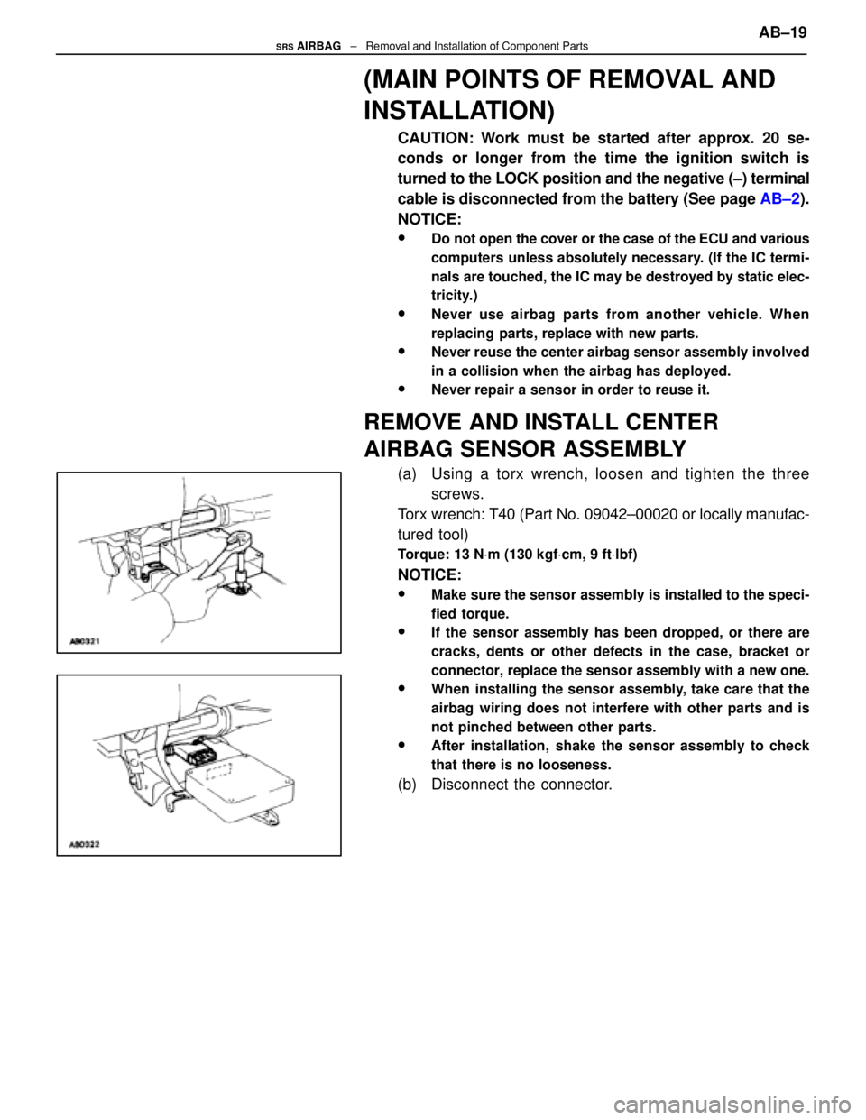
(a) Using a torx wrench, loosen and tighten the three screws.
Torx wrench: T40 (Part No. 09042±00020 or locally manufac-
tured tool)
Torque: 13 N Vm (130 kgf Vcm, 9 ft Vlbf)
NOTICE:
wMake sure the sensor assembly is installed to the speci-
fied torque.
wIf the sensor assembly has been dropped, or there are
cracks, dents or other defects in the case, bracket or
connector, replace the sensor assembly with a new one.
wWhen installing the sensor assembly, take care that the
airbag wiring does not interfere with other parts and is
not pinched between other parts.
wAfter installation, shake the sensor assembly to check
that there is no looseness.
(b) Disconnect the connector. AB±19
SRS AIRBAG
± Removal and Installation of Component Parts
WhereEverybodyKnowsYourName
Page 234 of 4087
REPLACEMENT OF REPAIR WIRE
FOR FRONT AIRBAG SENSOR
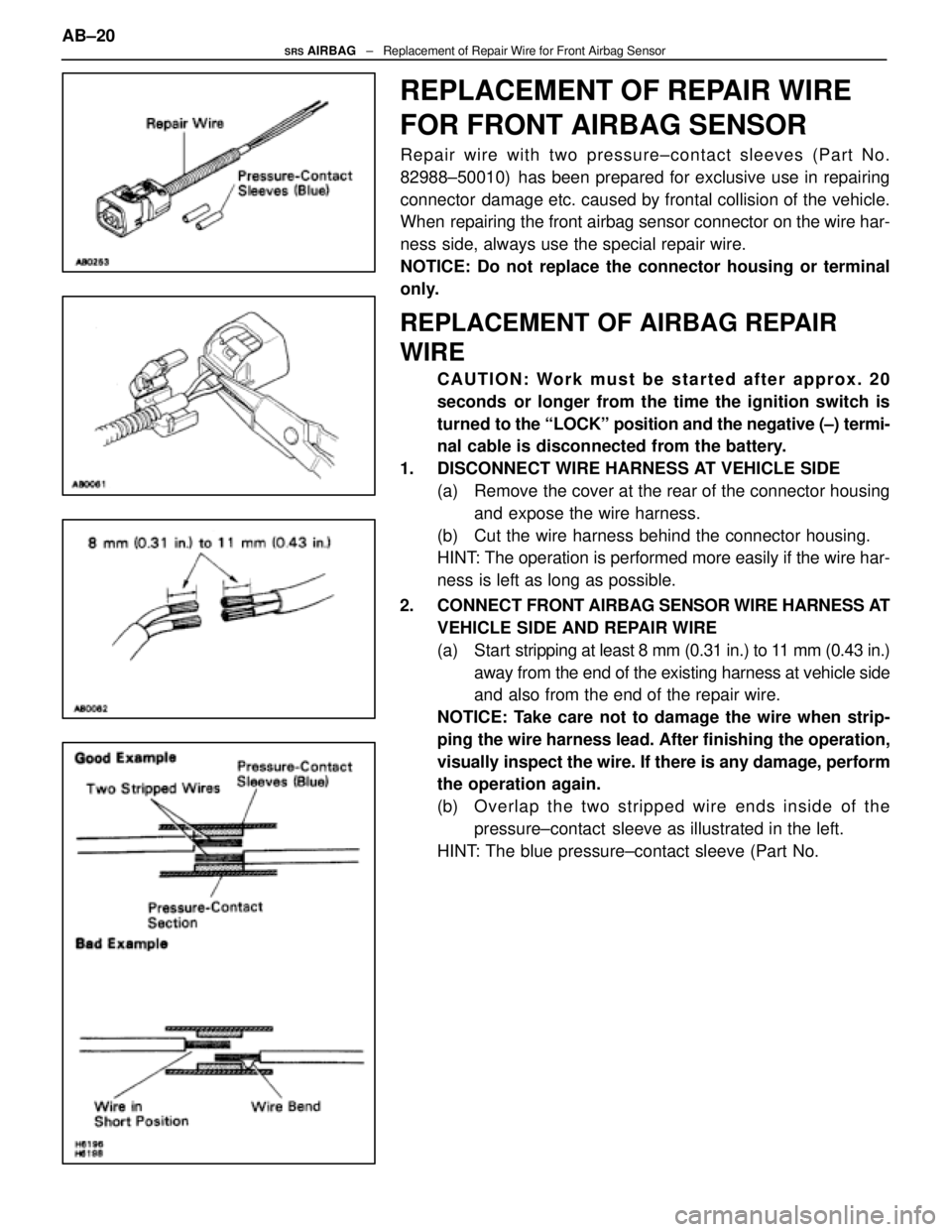
Repair wire with two pressure±contact sleeves (Part No.
82988±50010) has been prepared for exclusive use in repairing
connector damage etc. caused by frontal collision of the vehicle.
When repairing the front airbag sensor connector on the wire har-
ness side, always use the special repair wire.
NOTICE: Do not replace the connector housing or terminal
only.
REPLACEMENT OF AIRBAG REPAIR
WIRE
CAUTION: Work must be started after approx. 20
seconds or longer from the time the ignition switch is
turned to the ªLOCKº position and the negative (±) termi-
nal cable is disconnected from the battery.
1. DISCONNECT WIRE HARNESS AT VEHICLE SIDE (a) Remove the cover at the rear of the connector housingand expose the wire harness.
(b) Cut the wire harness behind the connector housing.
HINT: The operation is performed more easily if the wire har-
ness is left as long as possible.
2. CONNECT FRONT AIRBAG SENSOR WIRE HARNESS AT
VEHICLE SIDE AND REPAIR WIRE
(a) Start s tripping at least 8 mm (0.31 in.) to 11 mm (0.43 in.)
away from the end of the existing harness at vehicle side
and also from the end of the repair wire.
NOTICE: Take care not to damage the wire when strip-
ping the wire harness lead. After finishing the operation,
visually inspect the wire. If there is any damage, perform
the operation again.
(b) O ve rla p th e two stri pped wire ends inside of the
pressure±contact sleeve as illustrated in the left.
HINT: The blue pressure±contact sleeve (Part No.
AB±20
SRS AIRBAG
± Replacement of Repair Wire for Front Airbag Sensor
WhereEverybodyKnowsYourName
Page 235 of 4087
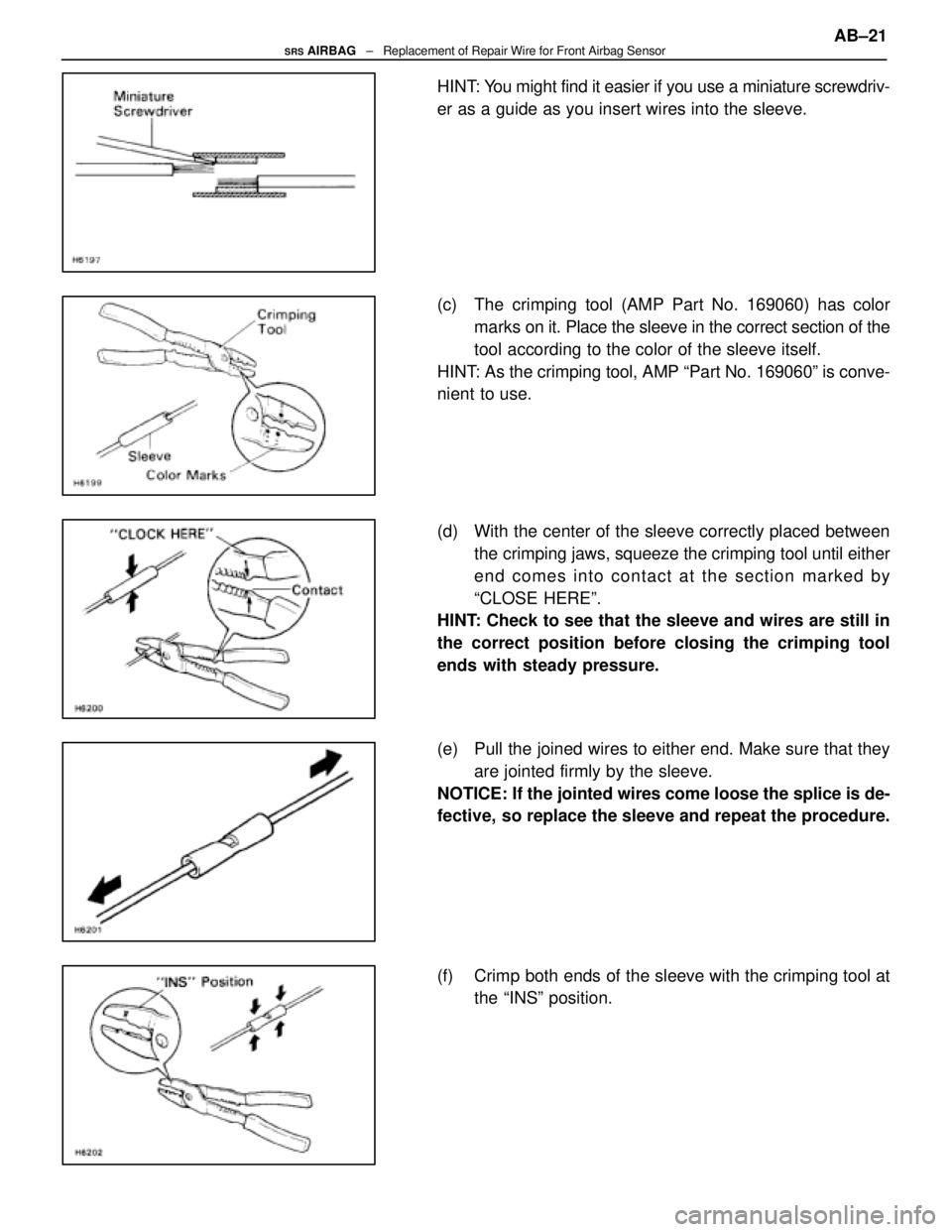
HINT: You might find it easier if you use a miniature screwdriv-
er as a guide as you insert wires into the sleeve.
(c) The crimping tool (AMP Part No. 169060) has colormarks on it. Place the sleeve in the correct section of the
tool according to the color of the sleeve itself.
HINT: As the crimping tool, AMP ªPart No. 169060º is conve-
nient to use.
(d) With the center of the sleeve correctly placed between the crimping jaws, squeeze the crimping tool until either
end comes into contact at the section marked by
ªCLOSE HEREº.
HINT: Check to see that the sleeve and wires are still in
the correct position before closing the crimping tool
ends with steady pressure.
(e) Pull the joined wires to either end. Make sure that they
are jointed firmly by the sleeve.
NOTICE: If the jointed wires come loose the splice is de-
fective, so replace the sleeve and repeat the procedure.
(f) Crimp both ends of the sleeve with the crimping tool at the ªINSº position. AB±21
SRS AIRBAG
± Replacement of Repair Wire for Front Airbag Sensor
WhereEverybodyKnowsYourName
Page 236 of 4087
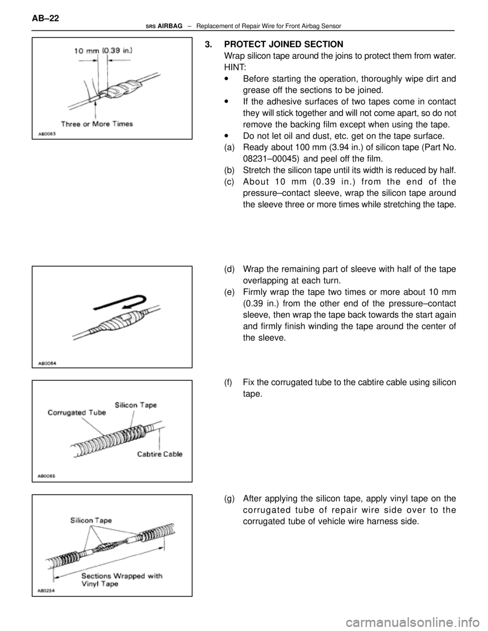
3. PROTECT JOINED SECTIONWrap silicon tape around the joins to protect them from water.
HINT:
wBefore starting the operation, thoroughly wipe dirt and
grease off the sections to be joined.
wIf the adhesive surfaces of two tapes come in contact
they will stick together and will not come apart, so do not
remove the backing film except when using the tape.
wDo not let oil and dust, etc. get on the tape surface.
(a) Ready about 100 mm (3.94 in.) of silicon tape (Part No.
08231±00045) and peel off the film.
(b) Stretch the silicon tape until its width is reduced by half.
(c) About 10 mm (0.39 in.) from the end of the pressure±contact sleeve, wrap the silicon tape around
the sleeve three or more times while stretching the tape.
(d) Wrap the remaining part of sleeve with half of the tape overlapping at each turn.
(e) Firmly wrap the tape two times or more about 10 mm (0.39 in.) from the other end of the pressure±contact
sleeve, then wrap the tape back towards the start again
and firmly finish winding the tape around the center of
the sleeve.
(f) Fix the corrugated tube to the cabtire cable using silicon tape.
(g) After applying the silicon tape, apply vinyl tape on the corrugated tube of repair wire side over to the
corrugated tube of vehicle wire harness side.
AB±22
SRS AIRBAG
± Replacement of Repair Wire for Front Airbag Sensor
WhereEverybodyKnowsYourName
Page 237 of 4087

TROUBLESHOOTING
AB±23SRS AIRBAG ± Troubleshooting
WhereEverybodyKnowsYourName
Page 238 of 4087
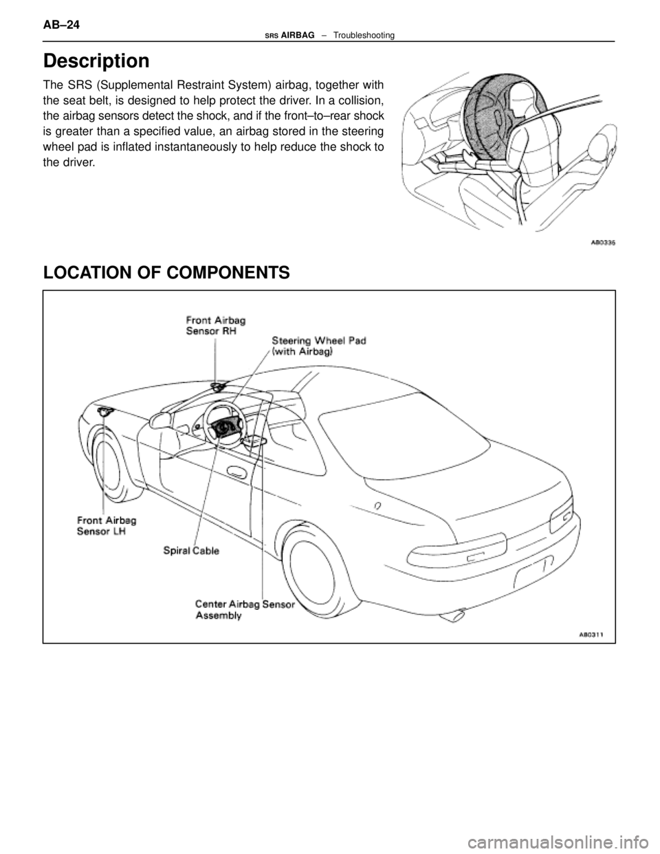
Description
The SRS (Supplemental Restraint System) airbag, together with
the seat belt, is designed to help protect the driver. In a collision,
the airbag sensors detect the shock, and if the front±to±rear shock
is greater than a specified value, an airbag stored in the steering
wheel pad is inflated instantaneously to help reduce the shock to
the driver.
LOCATION OF COMPONENTS
AB±24SRS AIRBAG ± Troubleshooting
WhereEverybodyKnowsYourName
Page 239 of 4087

How To Proceed With Troubleshooting
Malfunction symptoms of the airbag system are difficult to confirm, so the diagnostic codes become the most
important source of information when troubleshooting. Perform troubleshooting of the airbag system in ac\
cor-
dance with the following procedure:
HINT: Do not disconnect the battery negative (±) terminal cable until st\
ep [ 3 ], Diagnostic Code Check and Re-
cording, has been completed.1. CUSTOMER PROBLEM ANALYSIS Using the CUSTOMER PROBLEM ANALYSIS CHECK SHEET (See page AB±29) for reference, ask the
customer in as much detail as possible about the problem.
2. WARNING LIGHT CHECK Check the airbag warning light. If the light remains on, a malfunction is sto\
red in the center airbag sensor,
assembly, so proceed to step [ 3 ]. If the airbag warning light is not on, a malf\
unction has occurred in the
airbag warning light circuit, so perform troubleshooting for code 22.
HINT: Code 22 is recorded when a malfunction occurs in the airbag warning li\
ght system.
If an open malfunction occurs in the airbag warning light system, the airb\
ag warning light does not light up,
so that until the malfunction is repaired, the diagnostic codes (includin\
g code 22) cannot be confirmed.
3. DIAGNOSTIC CODE CHECK AND RECORDING Check the diagnostic codes and make a note of any malfunction codes which are\
output. If a normal code
is output, an abnormality in the power source circuit may have occurred, so perform troubleshootin\
g for
source voltage in step [ 8 ].
If code 22 is output, skip steps [ 4 ] and [ 5 ] and proceed to step [ 7\
].
4. CLEARING OF MALFUNCTION CODE (EXCEPT CODE 41) Clear the malfunction code.
HINT: The malfunction code output in step [ 3 ] indicates that a malfunction \
has occurred in the circuit desig-
nated by the malfunction code, but does not indicate whether the malfunction \
is still occurring or whether
it was in the past.
Accordingly, it is necessary to find out the present condition of the malfunction oc\
currence by clearing the
malfunction code and performing the diagnostic code check again. If this\
operation is neglected and trou-
bleshooting is performed using only the malfunction code confirmed in step [ 3 ], isola\
ting the problem com-
ponent becomes difficult and invites mistaken diagnosis.
5. DIAGNOSTIC CODE CHECK AND RECORDING [ 6 ] SYMPTOM SIMULATION After repeating ignition switch ON±OFF operation (ON: wait 20 secs., OFF: wait 20 secs.) 5 times, check
the diagnostic codes. If any code other than code 41 is output, the malfunc\
tion is still occurring, so proceed
to step [ 7 ].
If code 41 only is output, the following three cases are possible:
w Intermittent trouble occurred previously, but it is now normal.
w The problem has been corrected, but clearing of code 41 has been forgott\
en.
w There is a malfunction in the circuit for code 41.
Focusing on the circuit of the malfunction code stored in step 3, use th\
e simulation method in step [ 6 ]
in order to simulate the malfunction. If the malfunction occurs, proceed t\
o step [ 7 ]; if not, proceed to step.
[ 12 ]. AB±25
SRS AIRBAG
± Troubleshooting
WhereEverybodyKnowsYourName
Page 240 of 4087
NOTICE: When connecting the battery after clearing the malfunction code, always\
do it with the igni-
tion switch in LOCK position. When the battery has been reconnected, turn the ignition switch to
ACC or ON position after at least 2 seconds have elapsed.
If the battery is reconnected with the ignition switch in ACC or ON posi\
tion, or the ignition switch
is turned to ACC or ON within 2 seconds of connecting the battery, it is possible that the diagnosis
system will not operate normally.
HINT: Determine the malfunction in the airbag system in step [ 6 ] by whethe\
r or not a malfunction code
other than code 41 is output.
7. DIAGNOSTIC CODE CHART Proceed to the appropriate flow chart in step [ 8 ] in accordance with the malfunction code found in step
[ 5 ] or [ 6 ].
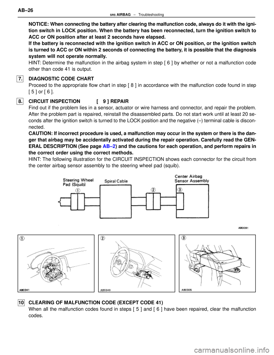
8. CIRCUIT INSPECTION [ 9 ] REPAIR Find out if the problem lies in a sensor, actuator or wire harness and connector, and repair the problem.
After the problem part is repaired, reinstall the disassembled parts. Do not \
start work until at least 20 se-
conds after the ignition switch is turned to the LOCK position and the negati\
ve (±) terminal cable is discon-
nected.
CAUTION: If incorrect procedure is used, a malfunction may occur in the system o\
r there is the dan-
ger that airbag may be accidentally activated during the repair operation. Carefully read the GEN-
ERAL DESCRIPTION (See page AB±2) and the cautions for each operation, and perform repairs in
the correct order using the correct methods.
HINT: The following illustration for the CIRCUIT INSPECTION shows each conne\
ctor for the circuit from
the center airbag sensor assembly to the steering wheel pad (squib).
10 CLEARING OF MALFUNCTION CODE (EXCEPT CODE 41) When all the malfunction codes found in steps [ 5 ] and [ 6 ] have been repa\
ired, clear the malfunction
codes.
AB±26
SRS AIRBAG
± Troubleshooting
WhereEverybodyKnowsYourName