LEXUS SC400 1991 Service Repair Manual
Manufacturer: LEXUS, Model Year: 1991,
Model line: SC400,
Model: LEXUS SC400 1991
Pages: 4087, PDF Size: 75.75 MB
LEXUS SC400 1991 Service Repair Manual
SC400 1991
LEXUS
LEXUS
https://www.carmanualsonline.info/img/36/57051/w960_57051-0.png
LEXUS SC400 1991 Service Repair Manual
Trending: height adjustment, ECO mode, clutch, transmission oil, timing belt, driver seat adjustment, low beam
Page 2691 of 4087
OKNG
OKNG
NOYES
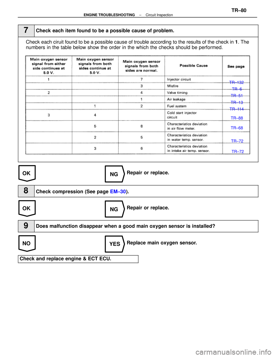
7Check each item found to be a possible cause of problem.
Check each ciruit found to be a possible cause of trouble according to the re\
sults of the check in 1. The
numbers in the table below show the order in the which the checks should be per\
formed.
TR±132
TR±6
TR±51
TR±13
TR±114
TR±88
TR±68
TR±72
TR±72
Repair or replace.
8Check compression (See page EM±30).
Repair or replace.
9Does malfunction disappear when a good main oxygen sensor is installed?
Replace main oxygen sensor.
Check and replace engine & ECT ECU.
±
ENGINE TROUBLESHOOTING Circuit InspectionTR±80
WhereEverybodyKnowsYourName
Page 2692 of 4087
±MEMO±TR±81
ENGINE TROUBLESHOOTING
WhereEverybodyKnowsYourName
Page 2693 of 4087
Diag. Code 27, 29Sub±Oxygen Sensor Circuit
CIRCUIT DESCRIPTION
The sub±oxygen sensor is installed on the exhaust pipe. Its construction\
and operation is the same as the main
oxygen sensor on page TR±62.
Code No.Diagnostic Code Detecting ConditionTrouble Area
(1) Open or short in heater circuit of sub±oxygen
sensor for 0.5 sec. or more.
�Open or short in heater circuit of sub±oxygen
sensor
� Sub±oxygen sensor heater.
� ECU
27
�
29(2) Main oxygen sensor signal is 0.45 V or more and sub±oxygen sensor signal is 0.45 V or less
under sonditions (a) and (b).
(2 trip detection logic) *
(a) Coolant temp.: 80 5C (176 5F) or more.
(b) Accel. pedal: Fully depressed for 2 sec. or more.
�Open or short in sub±oxygen sensor circuit.
� Sub±oxygen sensor
� ECU
*: See page TR±21.
HINT: Diag. code 27 is for the left bank sub±oxygen sensor circuit.
Diag. code 29 is for the right bank sub±oxygen sensor circuit.
TR±82
±
ENGINE TROUBLESHOOTING Circuit Inspection
WhereEverybodyKnowsYourName
Page 2694 of 4087
CIRCUIT DESCRIPTION (Cont'd)
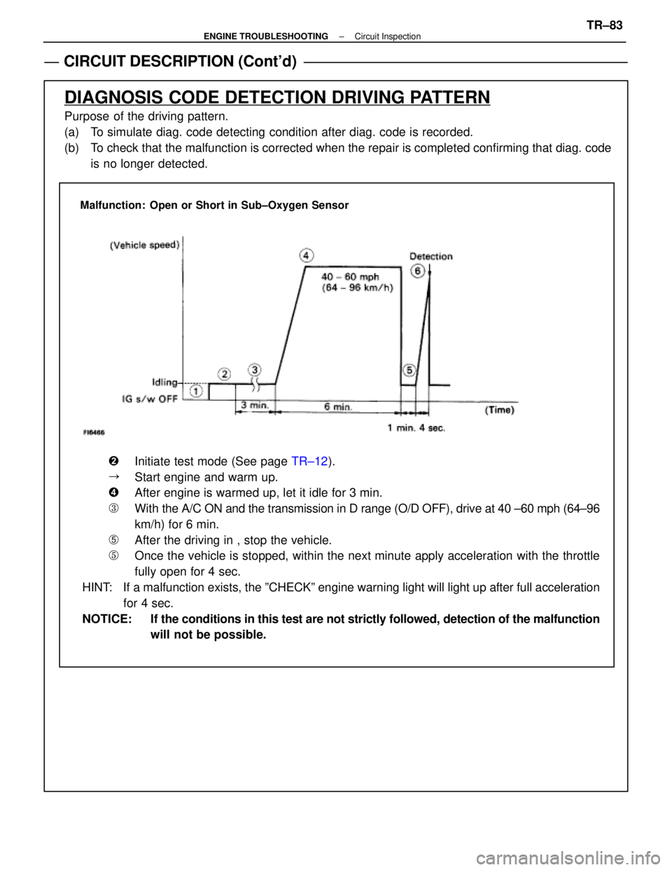
DIAGNOSIS CODE DETECTION DRIVING PATTERN
Purpose of the driving pattern.
(a) To simulate diag. code detecting condition after diag. code is recorded.
(b) To check that the malfunction is corrected when the repair is completed co\
nfirming that diag. codeis no longer detected.
Malfunction: Open or Short in Sub±Oxygen Sensor
�Initiate test mode (See page TR±12).
�Start engine and warm up.
�After engine is warmed up, let it idle for 3 min.
�With the A/C ON and the transmission in D range (O/D OFF), drive at 40 ±\
60 mph (64±96
km/h) for 6 min.
�After the driving in , stop the vehicle.
�Once the vehicle is stopped, within the next minute apply acceleration w\
ith the throttle
fully open for 4 sec.
HINT: If a malfunction exists, the ºCHECKº engine warning light will light\
up after full acceleration for 4 sec.
NOTICE: If the conditions in this test are not strictly followed, detection of the\
malfunction will not be possible.
±
ENGINE TROUBLESHOOTING Circuit InspectionTR±83
WhereEverybodyKnowsYourName
Page 2695 of 4087
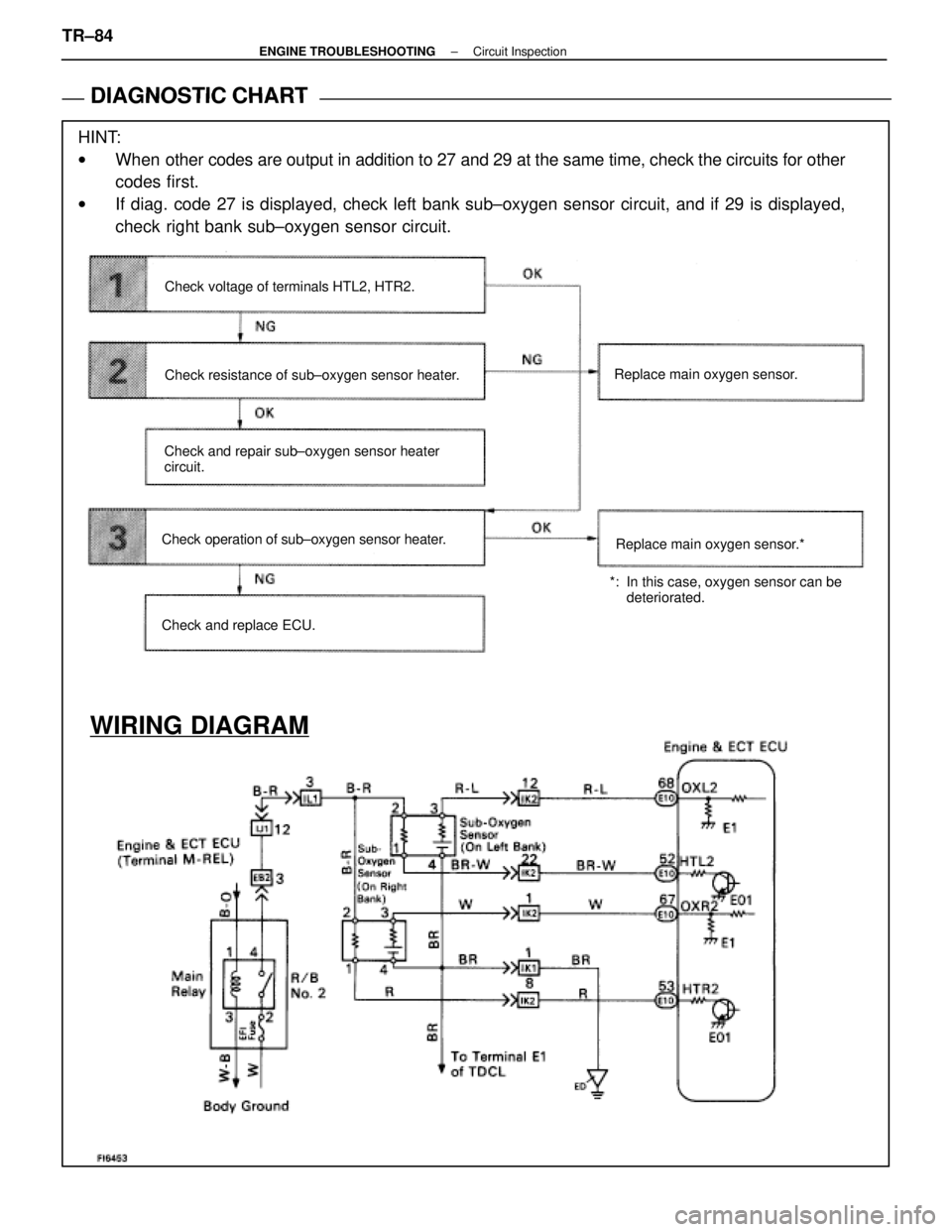
DIAGNOSTIC CHART
DIAGNOSTIC
CHART
HINT:
wWhen other codes are output in addition to 27 and 29 at the same time, check the ci\
rcuits for other
codes first.
w If diag. code 27 is displayed, check left bank sub±oxygen sensor circ\
uit, and if 29 is displayed,
check right bank sub±oxygen sensor circuit.
WIRING DIAGRAM
Check voltage of terminals HTL2, HTR2.
Check resistance of sub±oxygen sensor heater.
Check and repair sub±oxygen sensor heater
circuit.
Check operation of sub±oxygen sensor heater.
Check and replace ECU. Replace main oxygen sensor.
*: In this case, oxygen sensor can be deteriorated.
Replace main oxygen sensor.*
TR±84±
ENGINE TROUBLESHOOTING Circuit Inspection
WhereEverybodyKnowsYourName
Page 2696 of 4087
NGOK
OKNG
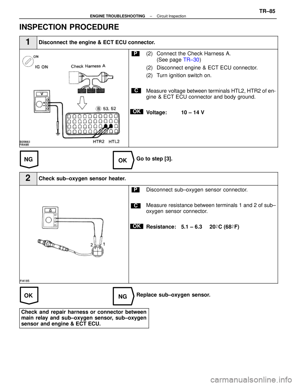
INSPECTION PROCEDURE
1Disconnect the engine & ECT ECU connector.
C
OK
P(2) Connect the Check Harness A.(See page TR±30)
(2) Disconnect engine & ECT ECU connector.
(2) Turn ignition switch on.
Measure voltage between terminals HTL2, HTR2 of en-
gine & ECT ECU connector and body ground.
Voltage: 10 ± 14 V
Go to step [3].
2Check sub±oxygen sensor heater.
C
OK
PDisconnect sub±oxygen sensor connector.
Measure resistance between terminals 1 and 2 of sub±
oxygen sensor connector.
Resistance: 5.1 ± 6.3 � 20 �C (68 �F)
Replace sub±oxygen sensor.
Check and repair harness or connector between
main relay and sub±oxygen sensor, sub±oxygen
sensor and engine & ECT ECU.
±
ENGINE TROUBLESHOOTING Circuit InspectionTR±85
WhereEverybodyKnowsYourName
Page 2697 of 4087
NGOK
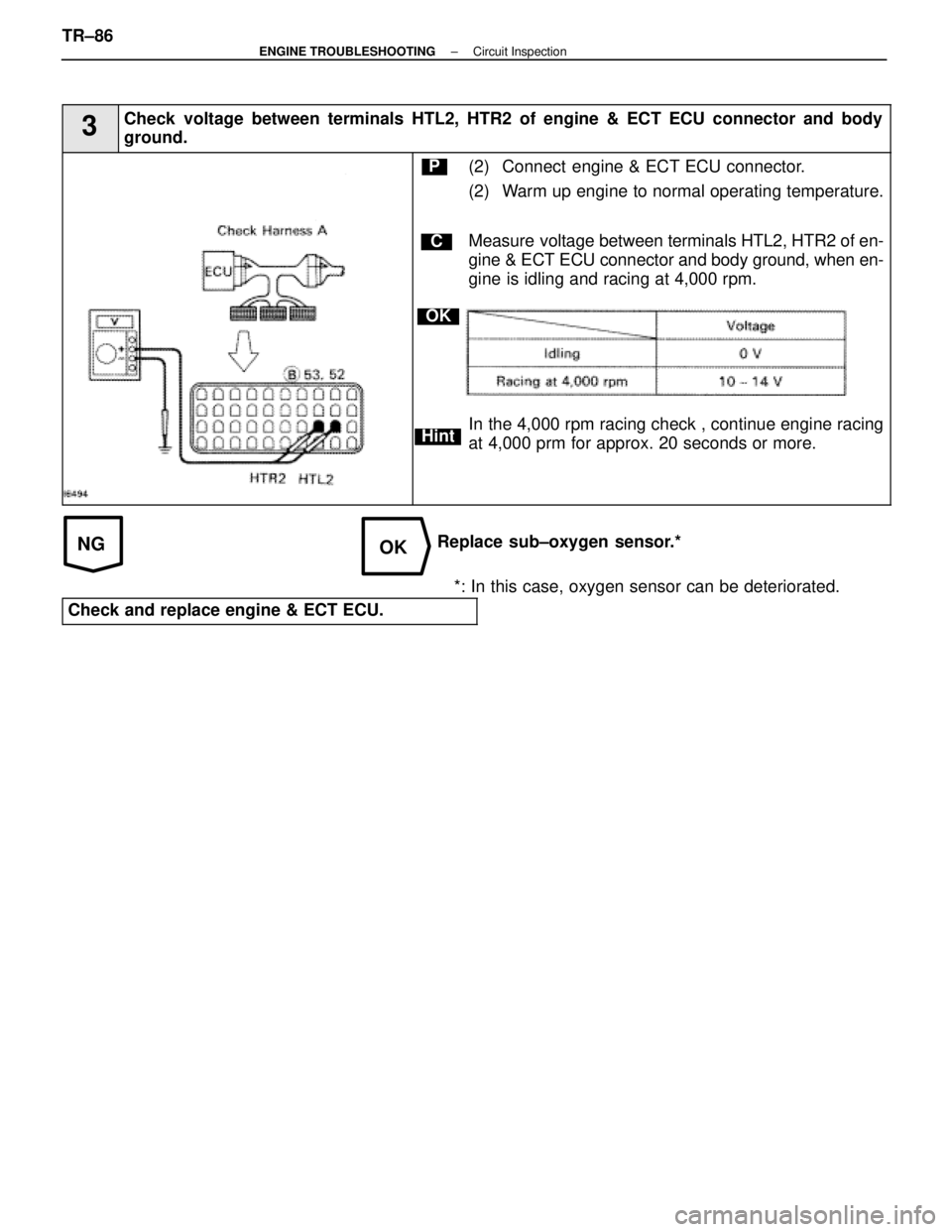
3Check voltage between terminals HTL2, HTR2 of engine & ECT ECU connector and \
body
ground.
C
OK
Hint
P(2) Connect engine & ECT ECU connector.
(2) Warm up engine to normal operating temperature.
Measure voltage between terminals HTL2, HTR2 of en-
gine & ECT ECU connector and body ground, when en-
gine is idling and racing at 4,000 rpm.
In the 4,000 rpm racing check , continue engine racing
at 4,000 prm for approx. 20 seconds or more.
Replace sub±oxygen sensor.**: In this case, oxygen sensor can be deteriorated.
Check and replace engine & ECT ECU.
TR±86±
ENGINE TROUBLESHOOTING Circuit Inspection
WhereEverybodyKnowsYourName
Page 2698 of 4087
±MEMO±
ENGINE TROUBLESHOOTINGTR±87
WhereEverybodyKnowsYourName
Page 2699 of 4087
Diag. Code 31Air Flow Meter Circuit
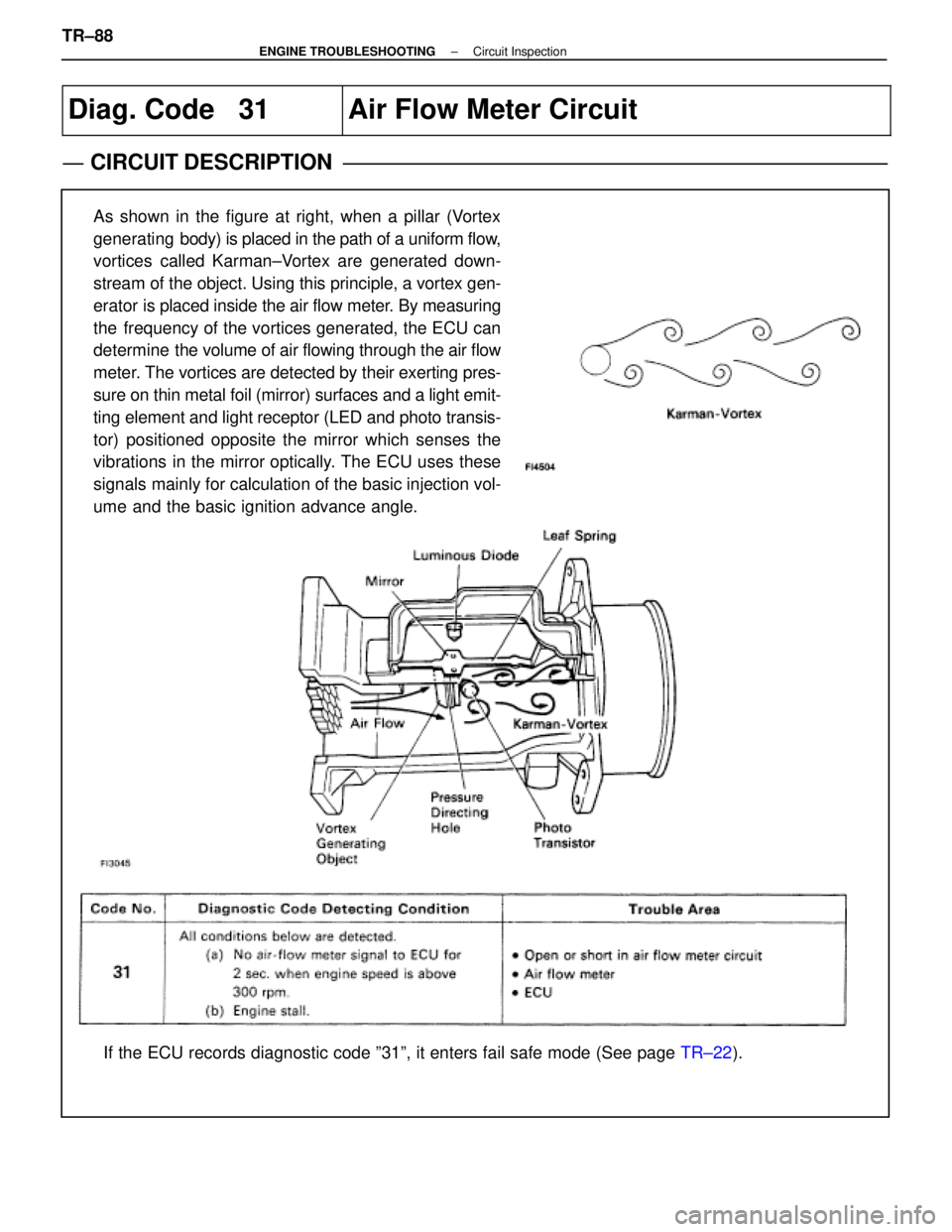
CIRCUIT DESCRIPTION
As shown in the figure at right, when a pillar (Vortex
generating body) is placed in the path of a uniform flow,
vortices called Karman±Vortex are generated down-
stream of the object. Using this principle, a vortex gen-
erator is placed inside the air flow meter. By measuring
the frequency of the vortices generated, the ECU can
determine the volume of air flowing through the air flow
meter. The vortices are detected by their exerting pres-
sure on thin metal foil (mirror) surfaces and a light emit-
ting element and light receptor (LED and photo transis-
tor) positioned opposite the mirror which senses the
vibrations in the mirror optically. The ECU uses these
signals mainly for calculation of the basic injection vol-
ume and the basic ignition advance angle.
If the ECU records diagnostic code º31º, it enters fail safe mode \
(See page TR±22).
TR±88
±
ENGINE TROUBLESHOOTING Circuit Inspection
WhereEverybodyKnowsYourName
Page 2700 of 4087
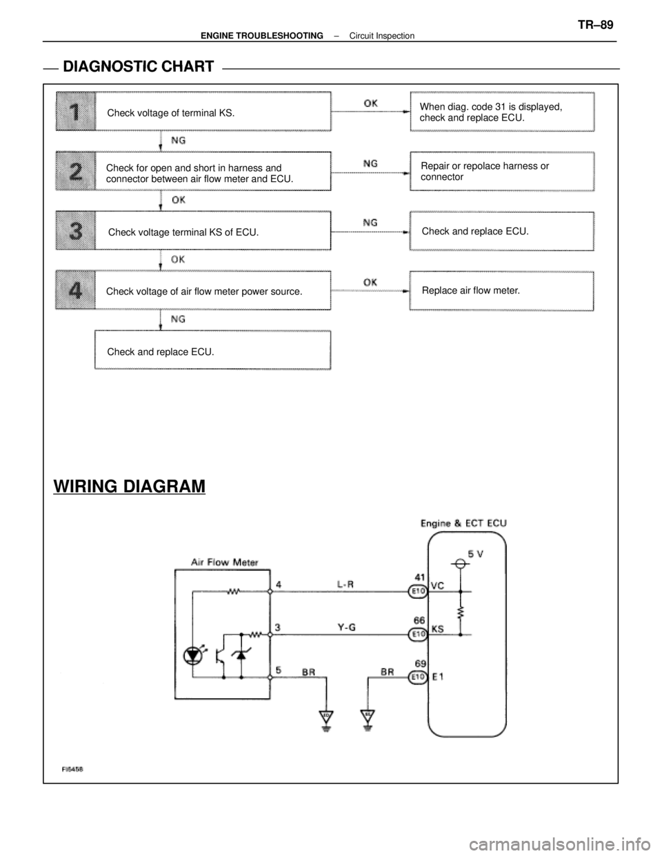
DIAGNOSTIC CHART
DIAGNOSTIC
CHART
WIRING DIAGRAM
Check and replace ECU.Replace air flow meter. Check and replace ECU.
Check voltage of air flow meter power source. Check voltage terminal KS of ECU.
Check for open and short in harness and
connector between air flow meter and ECU. Check voltage of terminal KS.
Repair or repolace harness or
connector
When diag. code 31 is displayed,
check and replace ECU.
±
ENGINE TROUBLESHOOTING Circuit InspectionTR±89
WhereEverybodyKnowsYourName
Trending: light, glove box, power steering fluid, brake pads replacement, catalytic converter, heating, fuse box diagram
