LEXUS SC400 1991 Service Repair Manual
Manufacturer: LEXUS, Model Year: 1991, Model line: SC400, Model: LEXUS SC400 1991Pages: 4087, PDF Size: 75.75 MB
Page 2911 of 4087
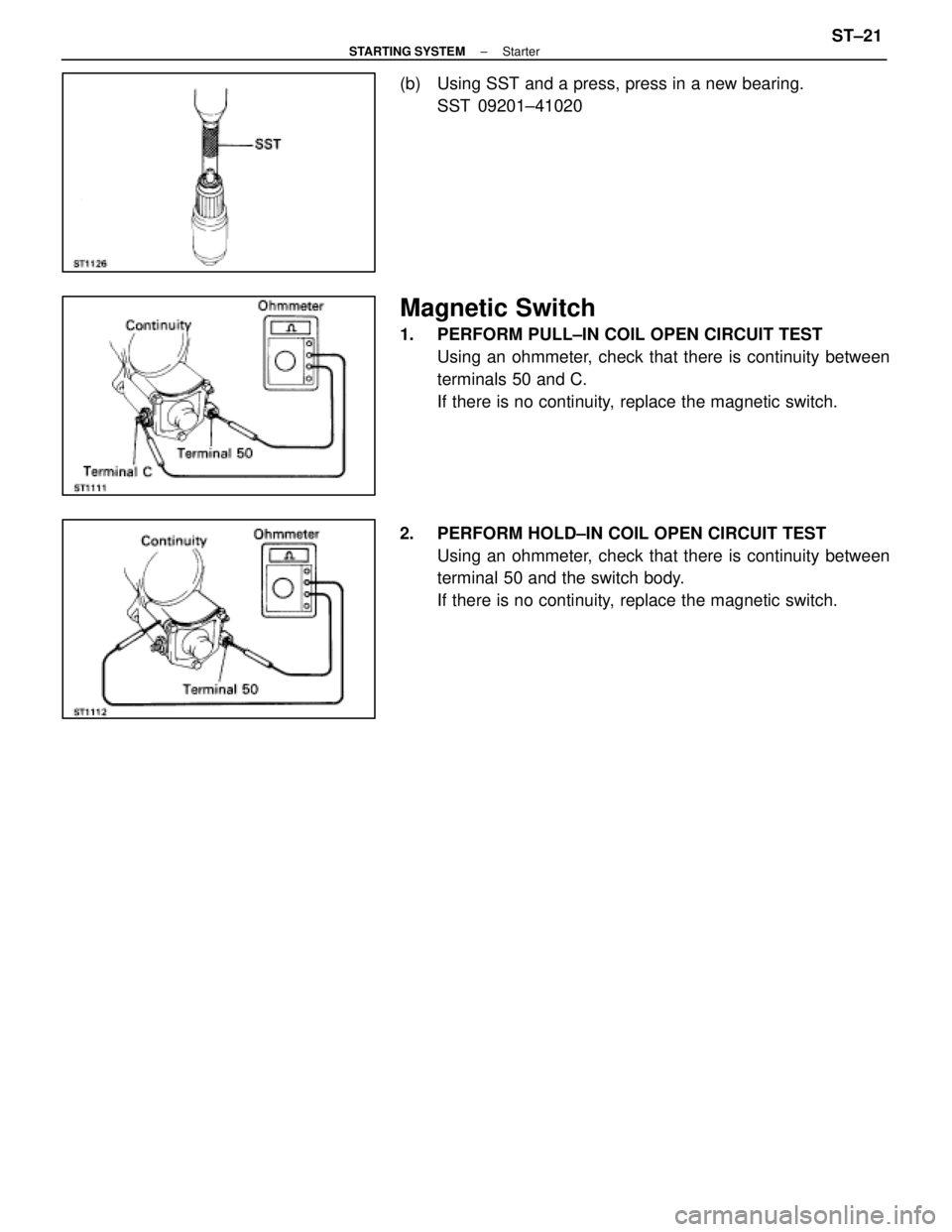
(b) Using SST and a press, press in a new bearing.SST 09201±41020
Magnetic Switch
1. PERFORM PULL±IN COIL OPEN CIRCUIT TESTUsing an ohmmeter, check that there is continuity between
terminals 50 and C.
If there is no continuity, replace the magnetic switch.
2. PERFORM HOLD±IN COIL OPEN CIRCUIT TEST Using an ohmmeter, check that there is continuity between
terminal 50 and the switch body.
If there is no continuity, replace the magnetic switch.
±
STARTING SYSTEM StarterST±21
WhereEverybodyKnowsYourName
Page 2912 of 4087
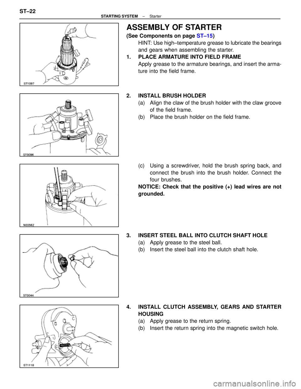
ASSEMBLY OF STARTER
(See Components on page ST±15)
HINT: Use high±temperature grease to lubricate the bearings
and gears when assembling the starter.
1. PLACE ARMATURE INTO FIELD FRAME Apply grease to the armature bearings, and insert the arma-
ture into the field frame.
2. INSTALL BRUSH HOLDER (a) Align the claw of the brush holder with the claw grooveof the field frame.
(b) Place the brush holder on the field frame.
(c) Using a screwdriver, hold the brush spring back, and connect the brush into the brush holder. Connect the
four brushes.
NOTICE: Check that the positive (+) lead wires are not
grounded.
3. INSERT STEEL BALL INTO CLUTCH SHAFT HOLE (a) Apply grease to the steel ball.
(b) Insert the steel ball into the clutch shaft hole.
4. INSTALL CLUTCH ASSEMBLY, GEARS AND STARTER HOUSING
(a) Apply grease to the return spring.
(b) Insert the return spring into the magnetic switch hole.
ST±22
±
STARTING SYSTEM Starter
WhereEverybodyKnowsYourName
Page 2913 of 4087
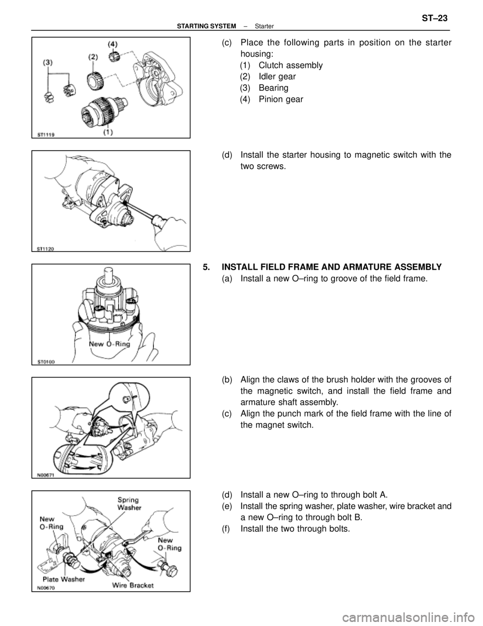
(c) Place the following parts in position on the starterhousing:
(1) Clutch assembly
(2) Idler gear
(3) Bearing
(4) Pinion gear
(d) Install the starter housing to magnetic switch with the two screws.
5. INSTALL FIELD FRAME AND ARMATURE ASSEMBLY (a) Install a new O±ring to groove of the field frame.
(b) Align the claws of the brush holder with the grooves ofthe magnetic switch, and install the field frame and
armature shaft assembly.
(c) Align the punch mark of the field frame with the line of the magnet switch.
(d) Install a new O±ring to through bolt A.
(e) Install the spring washer, plate washer, wire bracket and
a new O±ring to through bolt B.
(f) Install the two through bolts.
±
STARTING SYSTEM StarterST±23
WhereEverybodyKnowsYourName
Page 2914 of 4087
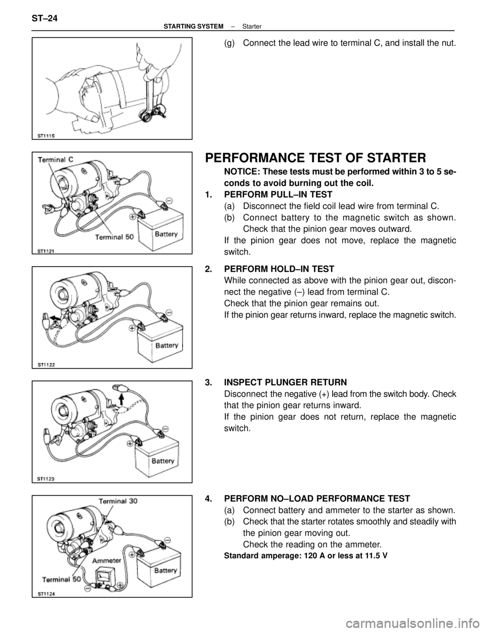
(g) Connect the lead wire to terminal C, and install the nut.
PERFORMANCE TEST OF STARTER
NOTICE: These tests must be performed within 3 to 5 se-
conds to avoid burning out the coil.
1. PERFORM PULL±IN TEST (a) Disconnect the field coil lead wire from terminal C.
(b) C onnect battery to the magnetic switch as shown.
Check that the pinion gear moves outward.
If the pinion gear does not move, replace the magnetic
switch.
2. PERFORM HOLD±IN TEST While connected as above with the pinion gear out, discon-
nect the negative (±) lead from terminal C.
Check that the pinion gear remains out.
If the pinion gear returns inward, replace the magnetic switch.
3. INSPECT PLUNGER RETURN Disconnect the negative (+) lead from the switch body. Check
that the pinion gear returns inward.
If the pinion gear does not return, replace the magnetic
switch.
4. PERFORM NO±LOAD PERFORMANCE TEST (a) Connect battery and ammeter to the starter as shown.
(b) Check that the starter rotates smoothly and steadily with
the pinion gear moving out.
Check the reading on the ammeter.
Standard amperage: 120 A or less at 11.5 V
ST±24±
STARTING SYSTEM Starter
WhereEverybodyKnowsYourName
Page 2915 of 4087
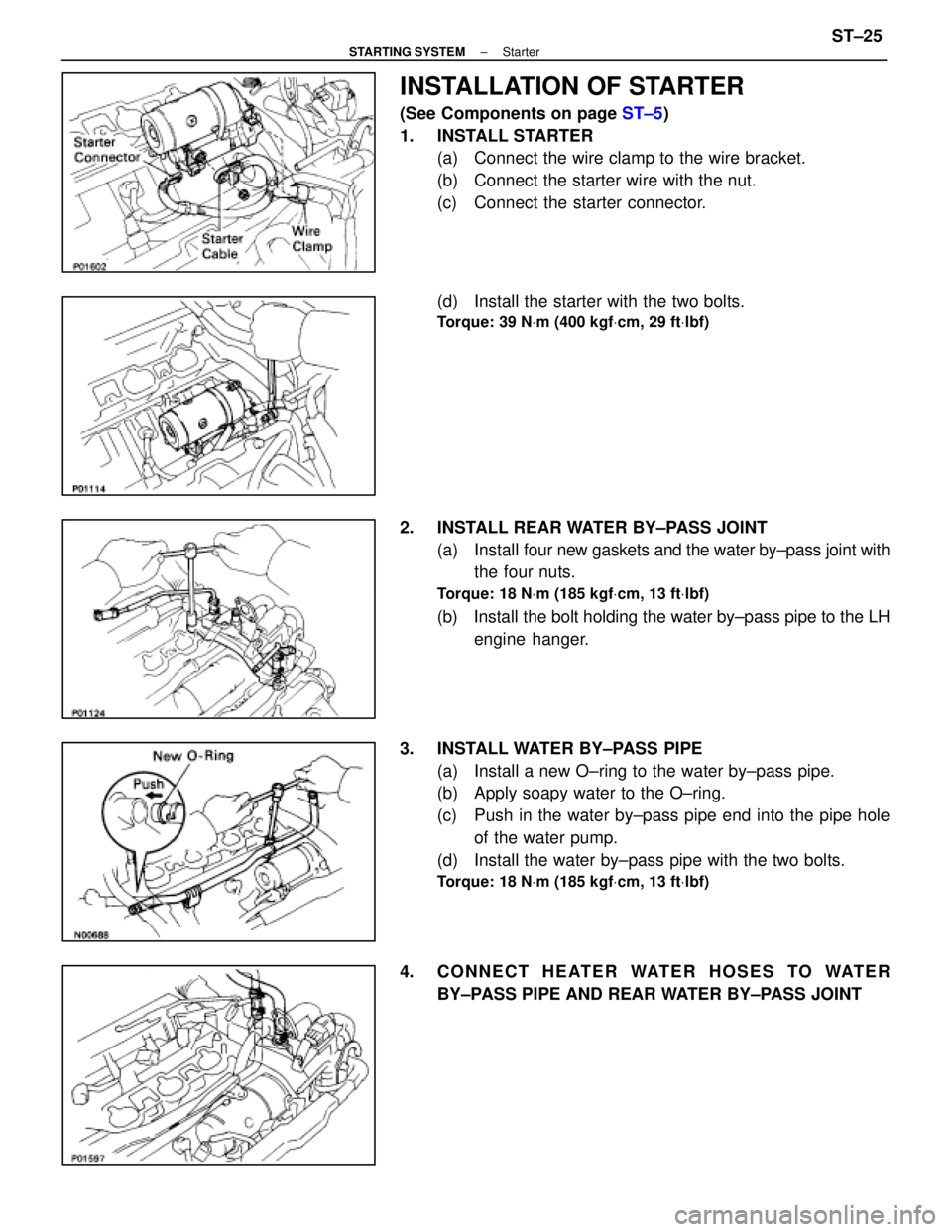
INSTALLATION OF STARTER
(See Components on page ST±5)
1. INSTALL STARTER (a) Connect the wire clamp to the wire bracket.
(b) Connect the starter wire with the nut.
(c) Connect the starter connector.
(d) Install the starter with the two bolts.
Torque: 39 N Vm (400 kgf Vcm, 29 ft Vlbf)
2. INSTALL REAR WATER BY±PASS JOINT
(a) Install four new gaskets and the water by±pass joint with
the four nuts.
Torque: 18 N Vm (185 kgf Vcm, 13 ft Vlbf)
(b) Install the bolt holding the water by±pass pipe to the LH
engine hanger.
3. INSTALL WATER BY±PASS PIPE (a) Install a new O±ring to the water by±pass pipe.
(b) Apply soapy water to the O±ring.
(c) Push in the water by±pass pipe end into the pipe holeof the water pump.
(d) Install the water by±pass pipe with the two bolts.
Torque: 18 N Vm (185 kgf Vcm, 13 ft Vlbf)
4. CONNECT HEATER WATER HOSES TO WATER
BY±PASS PIPE AND REAR WATER BY±PASS JOINT
±
STARTING SYSTEM StarterST±25
WhereEverybodyKnowsYourName
Page 2916 of 4087
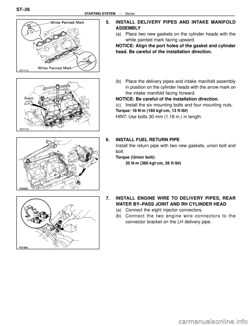
5. INSTALL DELIVERY PIPES AND INTAKE MANIFOLDASSEMBLY
(a) Place two new gaskets on the cylinder heads with thewhite painted mark facing upward.
NOTICE: Align the port holes of the gasket and cylinder
head. Be careful of the installation direction.
(b) Place the delivery pipes and intake manifold assembly in position on the cylinder heads with the arrow mark on
the intake manifold facing forward.
NOTICE: Be careful of the installation direction.
(c) Install the six mounting bolts and four mounting nuts.
Torque: 18 N Vm (185 kgf Vcm, 13 ft Vlbf)
HINT: Use bolts 30 mm (1.18 in.) in length.
6. INSTALL FUEL RETURN PIPE Install the return pipe with two new gaskets, union bolt and
bolt.
Torque (Union bolt):
35 NVm (360 kgf Vcm, 26 ft Vlbf)
7. INSTALL ENGINE WIRE TO DELIVERY PIPES, REAR
WATER BY±PASS JOINT AND RH CYLINDER HEAD
(a) Connect the eight injector connectors.
(b) C onnect the two engine wire connectors to the
connector bracket on the LH delivery pipe.
ST±26
±
STARTING SYSTEM Starter
WhereEverybodyKnowsYourName
Page 2917 of 4087
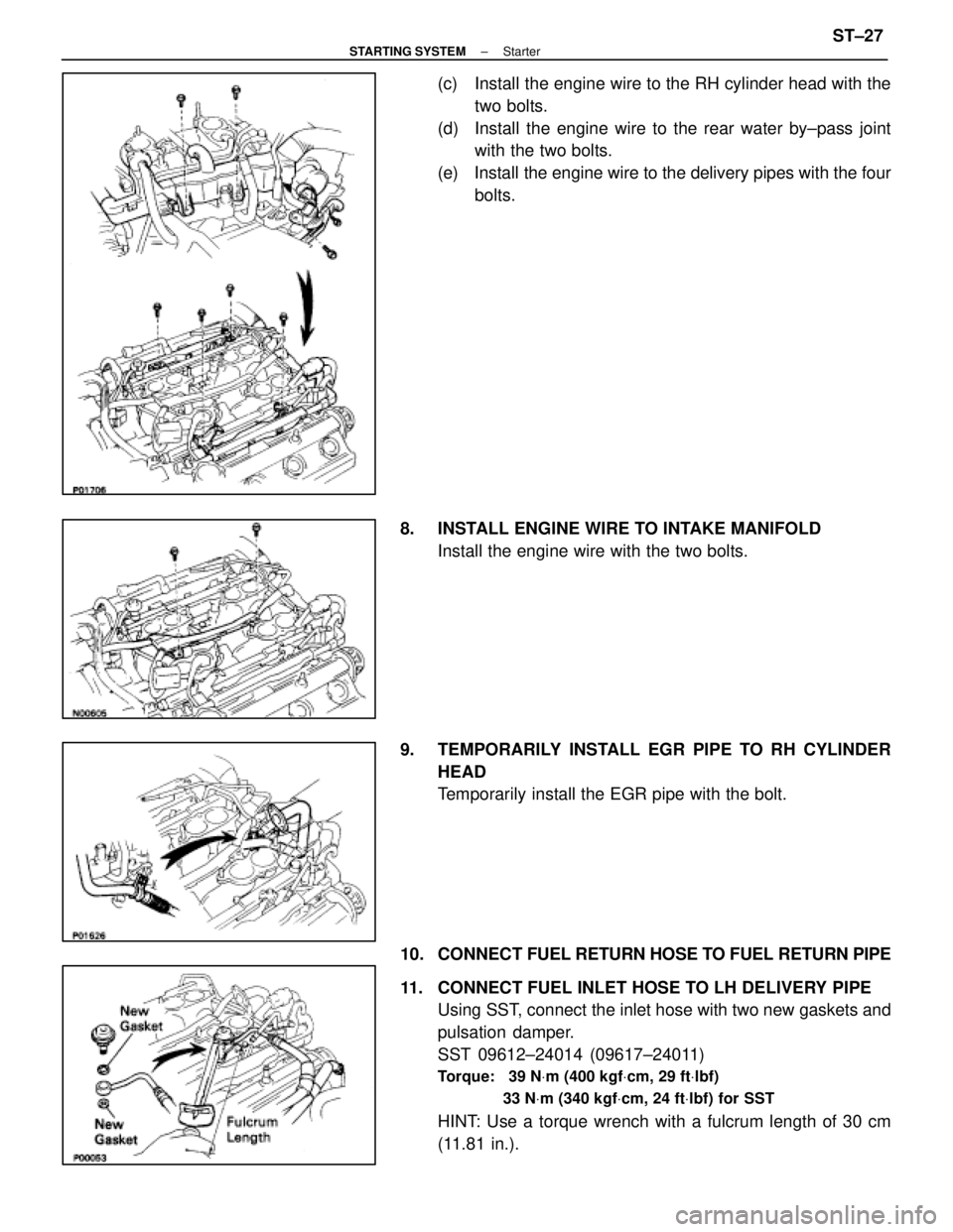
(c) Install the engine wire to the RH cylinder head with thetwo bolts.
(d) Install the engine wire to the rear water by±pass joint with the two bolts.
(e) Install the engine wire to the delivery pipes with the four bolts.
8. INSTALL ENGINE WIRE TO INTAKE MANIFOLD Install the engine wire with the two bolts.
9. TEMPORARILY INSTALL EGR PIPE TO RH CYLINDER HEAD
Temporarily install the EGR pipe with the bolt.
10. CONNECT FUEL RETURN HOSE TO FUEL RETURN PIPE
11. CONNECT FUEL INLET HOSE TO LH DELIVERY PIPE Using SST, connect the inlet hose with two new gaskets and
pulsation damper.
SST 09612±24014 (09617±24011)
Torque: 39 N Vm (400 kgf Vcm, 29 ft Vlbf)
33 N Vm (340 kgf Vcm, 24 ft Vlbf) for SST
HINT: Use a torque wrench with a fulcrum length of 30 cm
(11.81 in.).
±
STARTING SYSTEM StarterST±27
WhereEverybodyKnowsYourName
Page 2918 of 4087
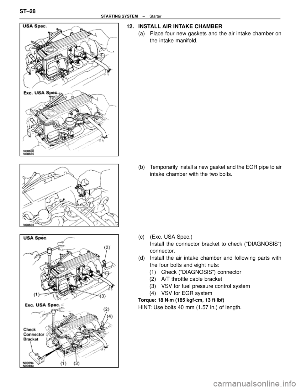
12. INSTALL AIR INTAKE CHAMBER(a) Place four new gaskets and the air intake chamber onthe intake manifold.
(b) Temporarily install a new gasket and the EGR pipe to air
intake chamber with the two bolts.
(c) (Exc. USA Spec.) Install the connector bracket to check (ºDIAGNOSISº)
connector.
(d) Install the air intake chamber and following parts with the four bolts and eight nuts:
(1) Check (ºDIAGNOSISº) connector
(2) A/T throttle cable bracket
(3) VSV for fuel pressure control system
(4) VSV for EGR system
Torque: 18 N Vm (185 kgf Vcm, 13 ft Vlbf)
HINT: Use bolts 40 mm (1.57 in.) of length.
ST±28
±
STARTING SYSTEM Starter
WhereEverybodyKnowsYourName
Page 2919 of 4087
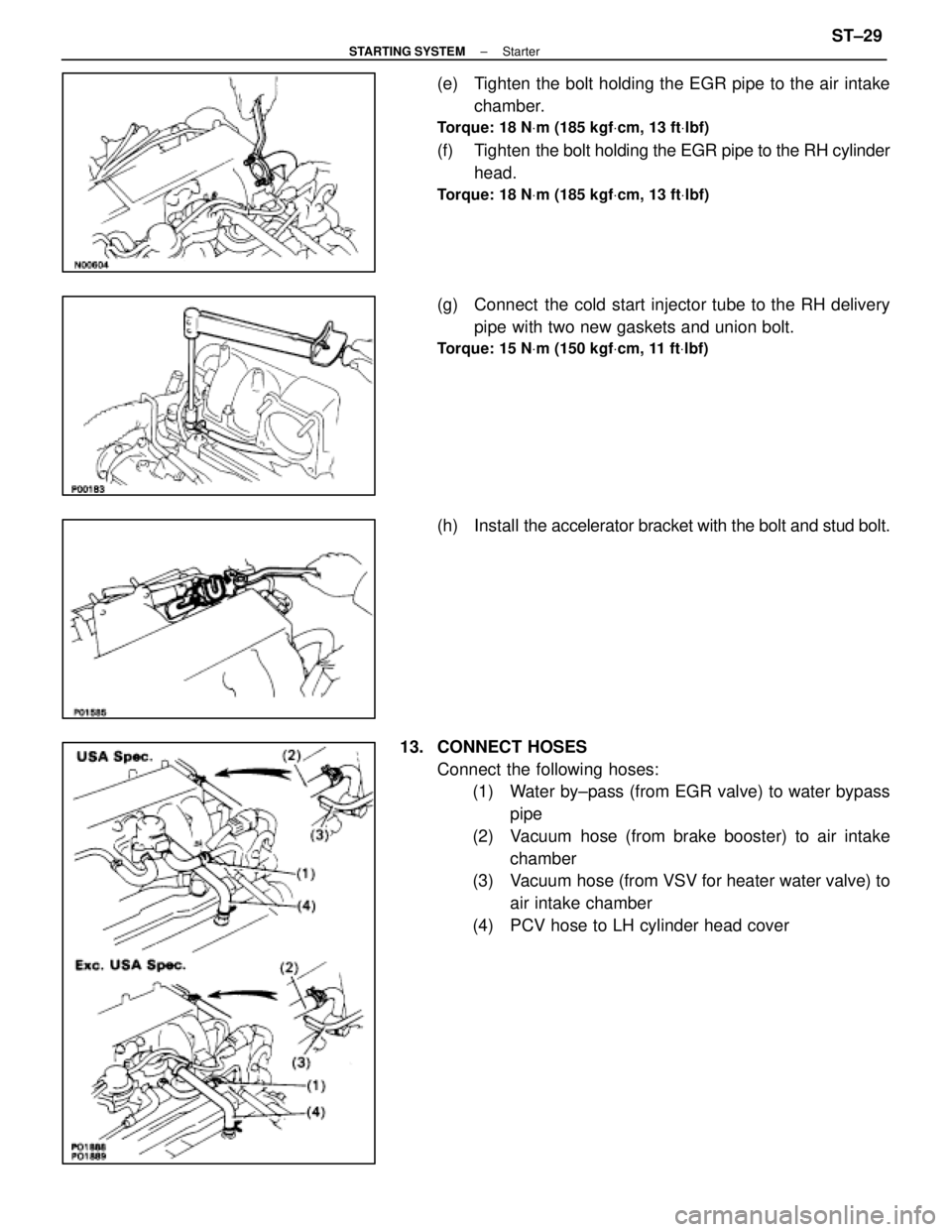
(e) Tighten the bolt holding the EGR pipe to the air intakechamber.
Torque: 18 N Vm (185 kgf Vcm, 13 ft Vlbf)
(f) Tighten the bolt holding the EGR pipe to the RH cylinder
head.
Torque: 18 N Vm (185 kgf Vcm, 13 ft Vlbf)
(g) Connect the cold start injector tube to the RH delivery
pipe with two new gaskets and union bolt.
Torque: 15 N Vm (150 kgf Vcm, 11 ft Vlbf)
(h) Install the accelerator bracket with the bolt and stud bolt.
13. CONNECT HOSES Connect the following hoses:(1) Water by±pass (from EGR valve) to water bypass
pipe
(2) Vacuum hose (from brake booster) to air intake chamber
(3) Vacuum hose (from VSV for heater water valve) to
air intake chamber
(4) PCV hose to LH cylinder head cover
±
STARTING SYSTEM StarterST±29
WhereEverybodyKnowsYourName
Page 2920 of 4087
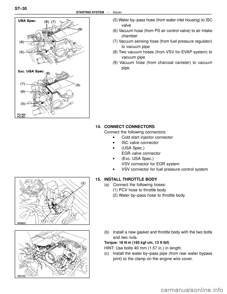
(5) Water by±pass hose (from water inlet housing) to ISC
valve
(6) Vacuum hose (from PS air control valve) to air intake chamber
(7) Vacuum sensing hose (from fuel pressure regulator) to vacuum pipe
(8) Two vacuum hoses (from VSV for EVAP system) to vacuum pipe
(9) Vacuum hose (from charcoal canister) to vacuum pipe.
14. CONNECT CONNECTORS Connect the following connectors:w Cold start injector connector
w ISC valve connector
w (USA Spec.)
EGR valve connector
w (Exc. USA Spec.)
VSV connector for EGR system
w VSV connector for fuel pressure control system
15. INSTALL THROTTLE BODY (a) Connect the following hoses:(1) PCV hose to throttle body
(2) Water by±pass hose to throttle body
(b) Install a new gasket and throttle body with the two bolts and two nuts.
Torque: 18 N Vm (185 kgf Vcm, 13 ft Vlbf)
HINT: Use bolts 40 mm (1.57 in.) in length.
(c) Install the water by±pass pipe (from rear water bypass
joint) to the clamp on the engine wire cover.
ST±30
±
STARTING SYSTEM Starter
WhereEverybodyKnowsYourName