LEXUS SC400 1991 Service Repair Manual
Manufacturer: LEXUS, Model Year: 1991,
Model line: SC400,
Model: LEXUS SC400 1991
Pages: 4087, PDF Size: 75.75 MB
LEXUS SC400 1991 Service Repair Manual
SC400 1991
LEXUS
LEXUS
https://www.carmanualsonline.info/img/36/57051/w960_57051-0.png
LEXUS SC400 1991 Service Repair Manual
Trending: start stop button, sunroof, EFI, transmission fluid, Throttle Position sensor, cooling, brake sensor
Page 2921 of 4087
(d) Connect the following hoses:(1) Water by±pass hose to the ISC valve
(2) (USA Spec.) Vacuum hose to throttle body
(3) (Exc. USA Spec.) Three vacuum hoses to throttle body
(4) Heater water hose to heater water valve
(e) Connect the following connectors: (1) Throttle position sensor connector
(2) (w/ TRAC) Sub±throttle position sensor connector
(3) (w/ TRAC) Sub±throttle actuator connector
16. INSTALL LOWER HIGH±TENSION CORD COVER (a) Connect the end portions of the high±tension cord to the
cord clamps
(b) Install the high±tension cord cover with the bolt.
±
STARTING SYSTEM StarterST±31
WhereEverybodyKnowsYourName
Page 2922 of 4087
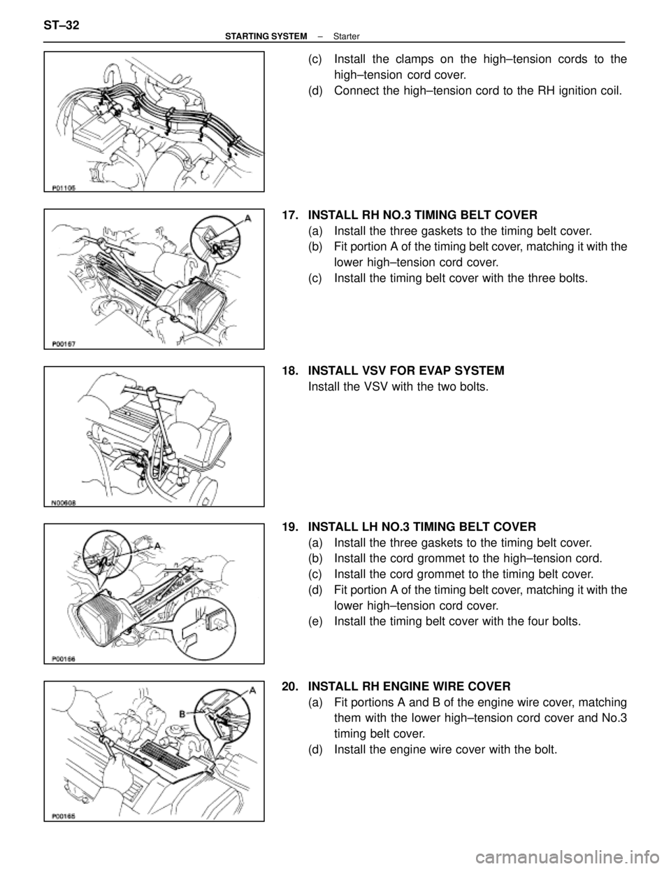
(c) Install the clamps on the high±tension cords to thehigh±tension cord cover.
(d) Connect the high±tension cord to the RH ignition coil.
17. INSTALL RH NO.3 TIMING BELT COVER (a) Install the three gaskets to the timing belt cover.
(b) Fit portion A of the timing belt cover, matching it with the
lower high±tension cord cover.
(c) Install the timing belt cover with the three bolts.
18. INSTALL VSV FOR EVAP SYSTEM Install the VSV with the two bolts.
19. INSTALL LH NO.3 TIMING BELT COVER (a) Install the three gaskets to the timing belt cover.
(b) Install the cord grommet to the high±tension cord.
(c) Install the cord grommet to the timing belt cover.
(d) Fit portion A of the timing belt cover, matching it with the
lower high±tension cord cover.
(e) Install the timing belt cover with the four bolts.
20. INSTALL RH ENGINE WIRE COVER (a) Fit portions A and B of the engine wire cover, matchingthem with the lower high±tension cord cover and No.3
timing belt cover.
(d) Install the engine wire cover with the bolt.
ST±32
±
STARTING SYSTEM Starter
WhereEverybodyKnowsYourName
Page 2923 of 4087
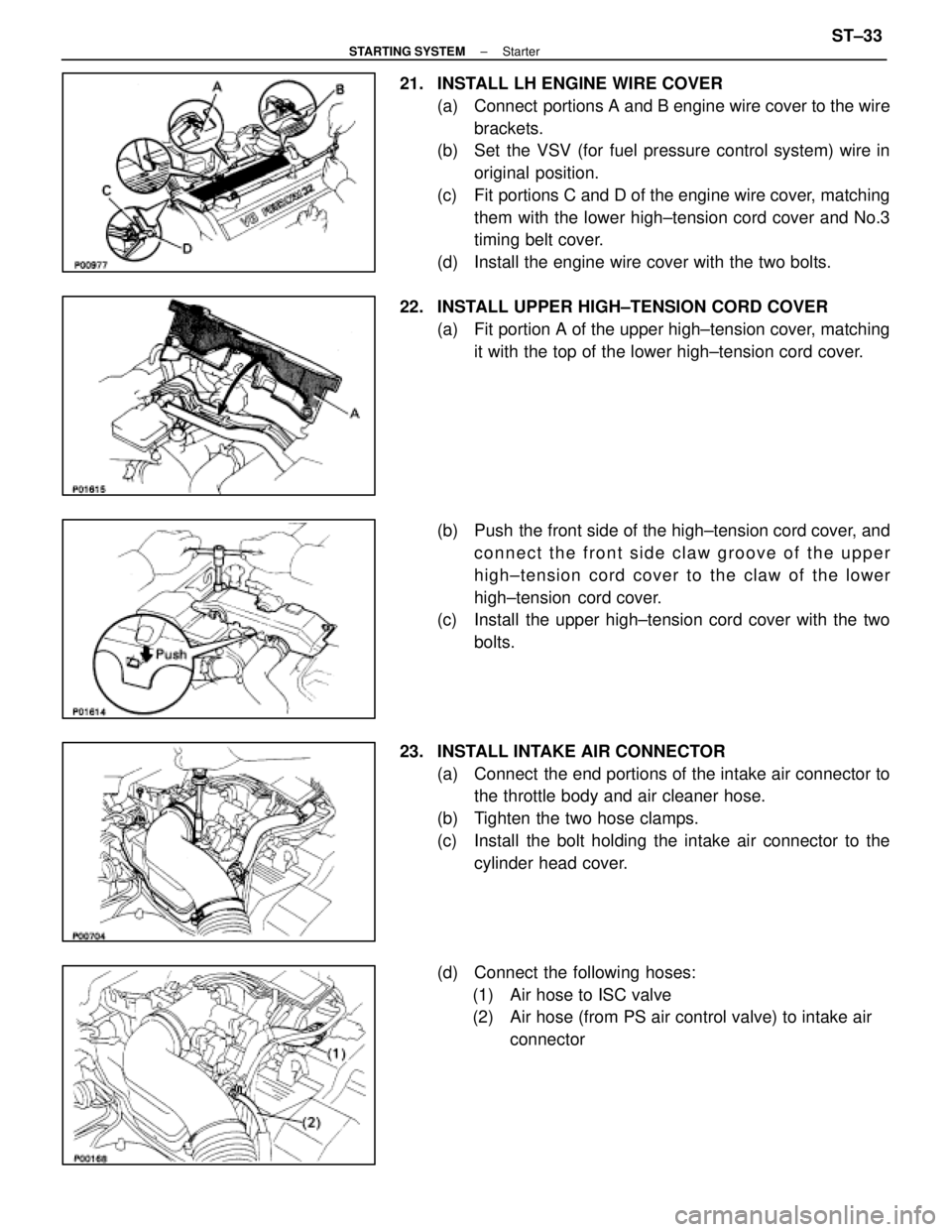
21. INSTALL LH ENGINE WIRE COVER(a) Connect portions A and B engine wire cover to the wirebrackets.
(b) Set the VSV (for fuel pressure control system) wire in
original position.
(c) Fit portions C and D of the engine wire cover, matching them with the lower high±tension cord cover and No.3
timing belt cover.
(d) Install the engine wire cover with the two bolts.
22. INSTALL UPPER HIGH±TENSION CORD COVER (a) Fit portion A of the upper high±tension cover, matchingit with the top of the lower high±tension cord cover.
(b) Push the front side of the high±tension cord cover, and connect the front side claw groove of the upper
high±tension cord cover to the claw of the lower
high±tension cord cover.
(c) Install the upper high±tension cord cover with the two
bolts.
23. INSTALL INTAKE AIR CONNECTOR (a) Connect the end portions of the intake air connector tothe throttle body and air cleaner hose.
(b) Tighten the two hose clamps.
(c) Install the bolt holding the intake air connector to the cylinder head cover.
(d) Connect the following hoses: (1) Air hose to ISC valve
(2) Air hose (from PS air control valve) to intake air connector
±
STARTING SYSTEM StarterST±33
WhereEverybodyKnowsYourName
Page 2924 of 4087
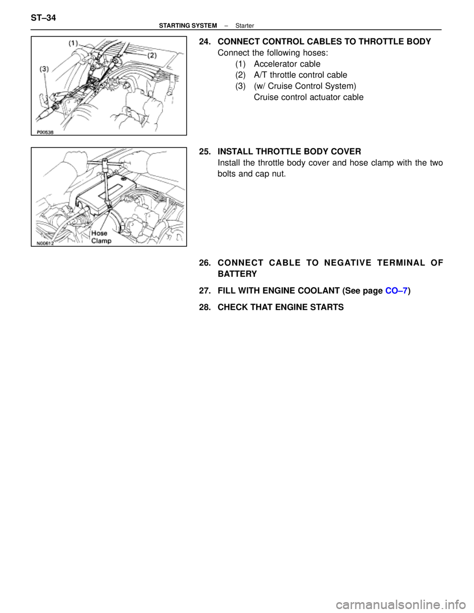
24. CONNECT CONTROL CABLES TO THROTTLE BODYConnect the following hoses:(1) Accelerator cable
(2) A/T throttle control cable
(3) (w/ Cruise Control System) Cruise control actuator cable
25. INSTALL THROTTLE BODY COVER Install the throttle body cover and hose clamp with the two
bolts and cap nut.
26. C O N N E C T C A B L E TO N E G AT I V E T E R M I N A L O F BATTERY
27. FILL WITH ENGINE COOLANT (See page CO±7)
28. CHECK THAT ENGINE STARTS
ST±34
±
STARTING SYSTEM Starter
WhereEverybodyKnowsYourName
Page 2925 of 4087
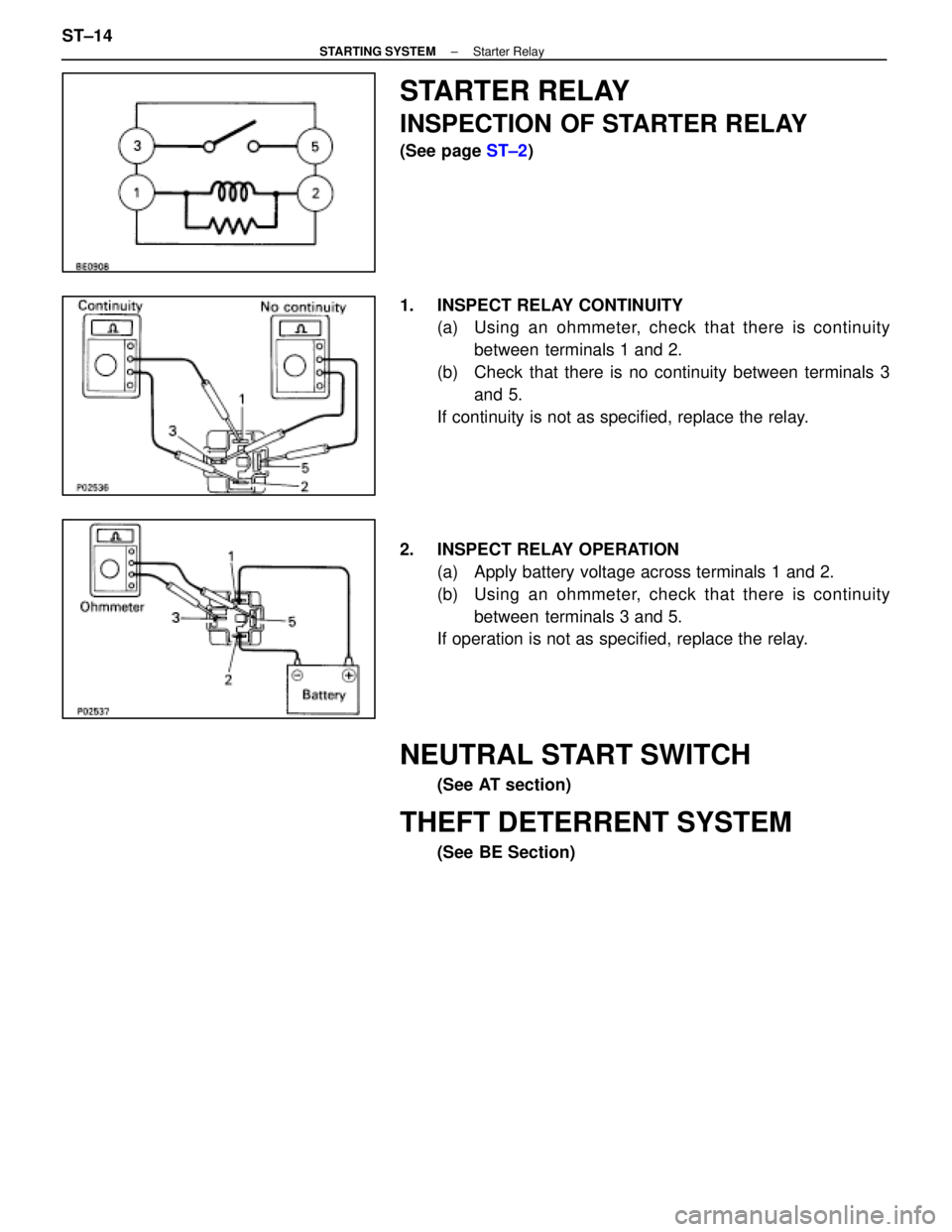
STARTER RELAY
INSPECTION OF STARTER RELAY
(See page ST±2)
1. INSPECT RELAY CONTINUITY (a) Using an ohmmeter, check that there is continuity
between terminals 1 and 2.
(b) Check that there is no continuity between terminals 3 and 5.
If continuity is not as specified, replace the relay.
2. INSPECT RELAY OPERATION (a) Apply battery voltage across terminals 1 and 2.
(b) Using an ohmmeter, check that there is continuitybetween terminals 3 and 5.
If operation is not as specified, replace the relay.
NEUTRAL START SWITCH
(See AT section)
THEFT DETERRENT SYSTEM
(See BE Section)
ST±14
±
STARTING SYSTEM Starter Relay
WhereEverybodyKnowsYourName
Page 2926 of 4087
SERVICE SPECIFICATIONS
SERVICE DATA
StarterRated voltage and output power12 V 1.4 kW
No±load characteristicCurrent 90 A or less at 11.5 V
rpm 3,500 rpm or more
Brush lengthSTD 15.5 mm0.610 in.
Limit 10.0 mm0.394 in.
CommutatorOuter diameter STD 30 mm1.18 in.
Limit 29 mm1.14 in.
Undercut depth STD 0.6 mm0.024 in.
Limit 0.2 mm0.008 in.
Circle runout Limit 0.05 mm0.0020 in.
Spring installed loadSTD 18±24 N
(1.79 ± 2.41 kgf, 3.9 ± 5.3 lbf)
Limit12 N1.2 kgf2.6 lbf
TORQUE SPECIFICATIONS
Part tightenedNVmkgf Vcmft Vlbf
Starter x Cylinder block3940029
±
STARTING SYSTEM Service SpecificationsST±15
WhereEverybodyKnowsYourName
Page 2927 of 4087
STARTER RELAY
INSPECTION OF STARTER RELAY
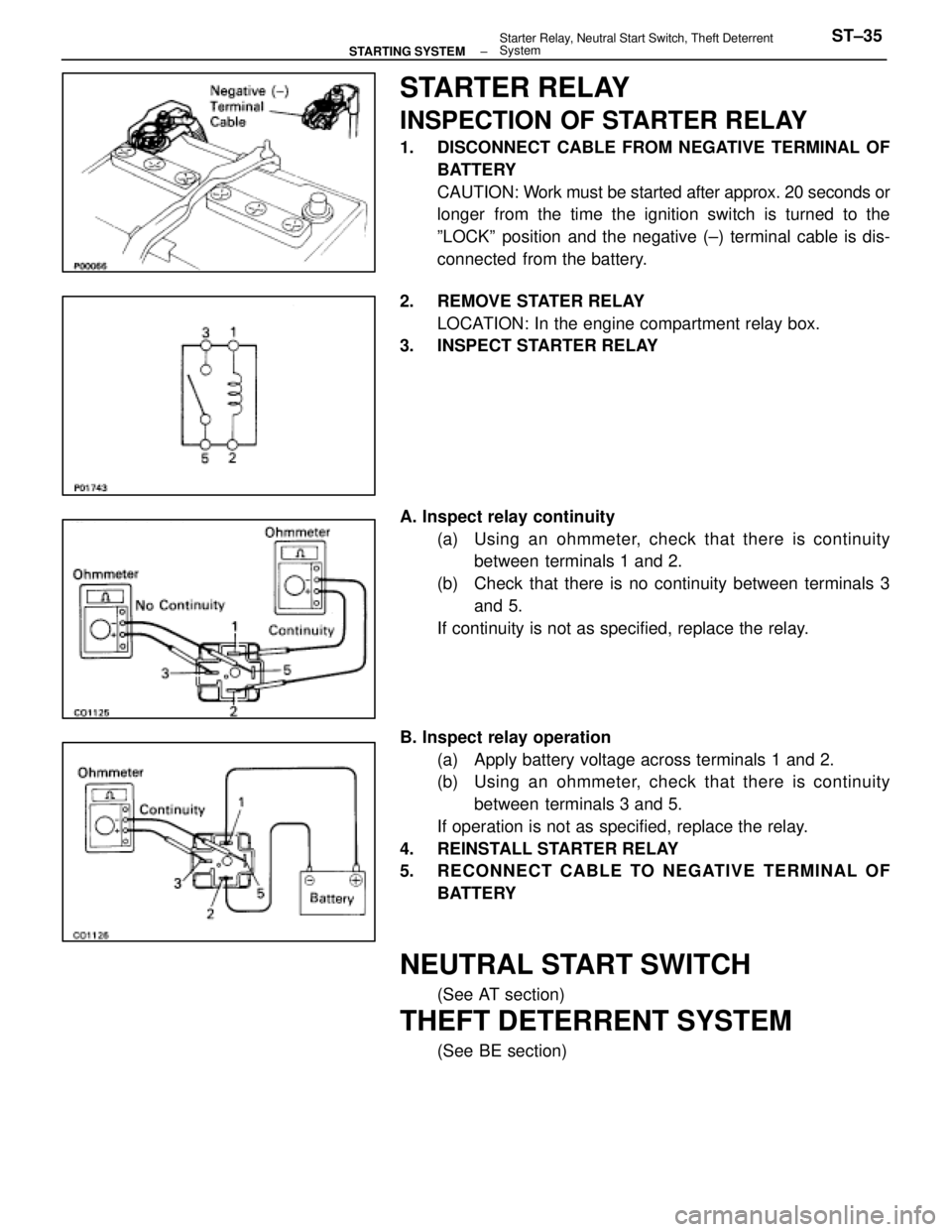
1. DISCONNECT CABLE FROM NEGATIVE TERMINAL OFBATTERY
CAUTION: Work must be started after approx. 20 seconds or
longer from the time the ignition switch is turned to the
ºLOCKº position and the negative (±) terminal cable is dis-
connected from the battery.
2. REMOVE STATER RELAY LOCATION: In the engine compartment relay box.
3. INSPECT STARTER RELAY
A. Inspect relay continuity
(a) Using an ohmmeter, check that there is continuitybetween terminals 1 and 2.
(b) Check that there is no continuity between terminals 3 and 5.
If continuity is not as specified, replace the relay.
B. Inspect relay operation (a) Apply battery voltage across terminals 1 and 2.
(b) Using an ohmmeter, check that there is continuitybetween terminals 3 and 5.
If operation is not as specified, replace the relay.
4. REINSTALL STARTER RELAY
5. RECONNECT CABLE TO NEGATIVE TERMINAL OF BATTERY
NEUTRAL START SWITCH
(See AT section)
THEFT DETERRENT SYSTEM
(See BE section)
±
STARTING SYSTEM Starter Relay, Neutral Start Switch, Theft Deterrent
SystemST±35
WhereEverybodyKnowsYourName
Page 2928 of 4087
SR±52).
IN±33).
WIRING DIAGRAM
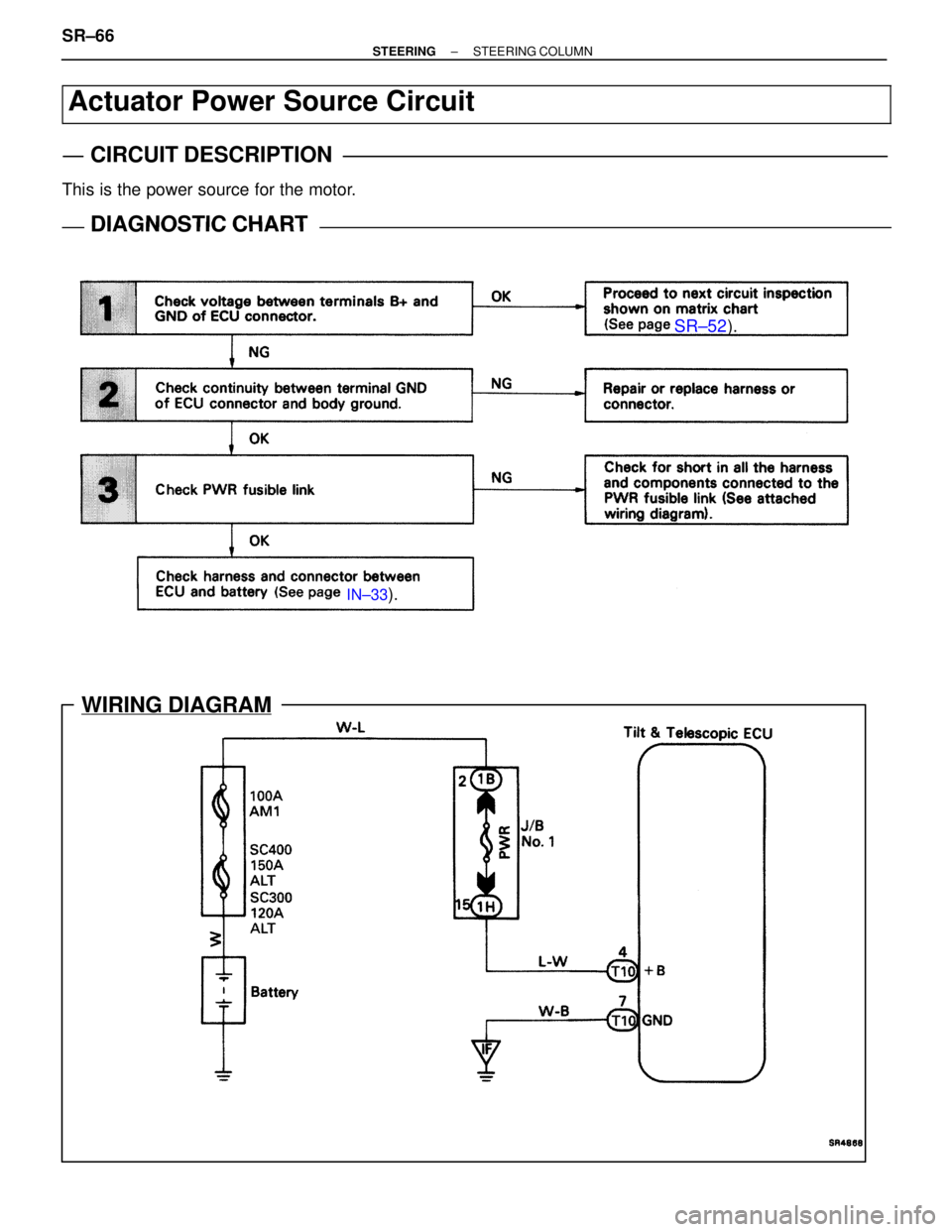
Actuator Power Source Circuit
CIRCUIT DESCRIPTION
This is the power source for the motor.
DIAGNOSTIC CHARTDIAGNOSTIC CHART
SR±66±
STEERING STEERING COLUMN
WhereEverybodyKnowsYourName
Page 2929 of 4087
NGOK
OKNG
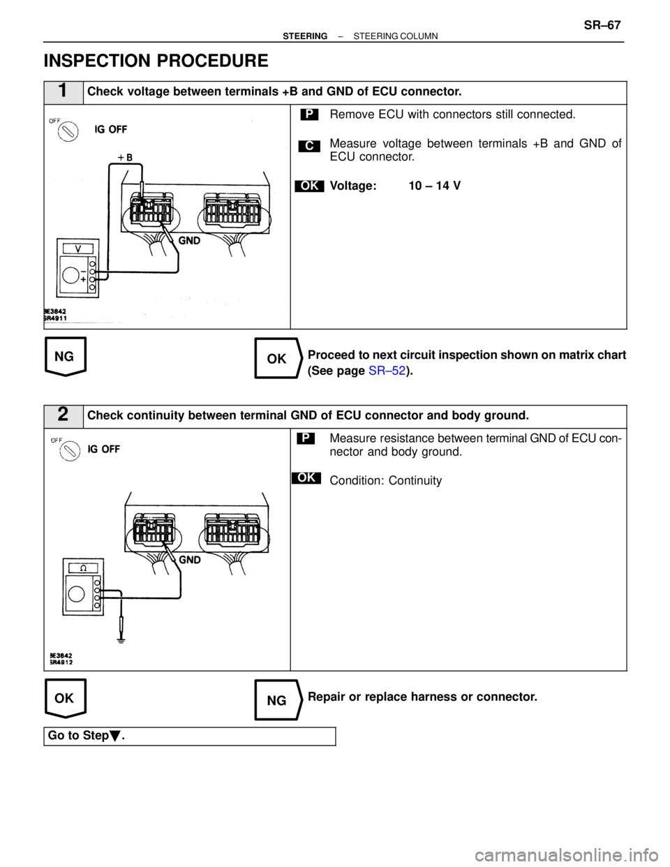
INSPECTION PROCEDURE
1Check voltage between terminals +B and GND of ECU connector.
C
OK
PRemove ECU with connectors still connected.
Measure voltage between terminals +B and GND of
ECU connector.
Voltage: 10 ± 14 V
Proceed to next circuit inspection shown on matrix chart
(See page SR±52).
2Check continuity between terminal GND of ECU connector and body ground.
OK
PMeasure resistance between terminal GND of ECU con-
nector and body ground.
Condition: Continuity
Repair or replace harness or connector.
Go to Step �.
±
STEERING STEERING COLUMNSR±67
WhereEverybodyKnowsYourName
Page 2930 of 4087
OKNG
3Check PWR fusible link.
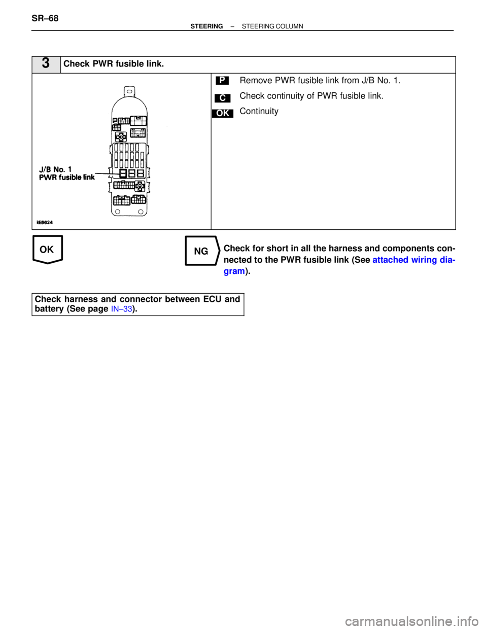
C
OK
PRemove PWR fusible link from J/B No. 1.
Check continuity of PWR fusible link.
Continuity
Check for short in all the harness and components con-
nected to the PWR fusible link (See attached wiring dia-
gram ).
Check harness and connector between ECU and
battery (See page
IN±33).
SR±68±
STEERING STEERING COLUMN
WhereEverybodyKnowsYourName
Trending: manual radio set, headrest, seat adjustment, battery location, transmission, clock, airbag


